Table of Contents
Advertisement
Quick Links
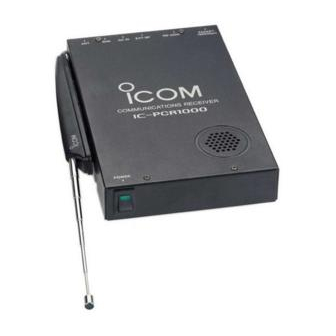
INSTRUCTION MANUAL
COMMUNICATIONS RECEIVER FOR COMPUTER
iPCR1000
This device complies with Part 15 of the FCC Rules. Operation is sub-
ject to the following two conditions: (1) This device may not cause
harmful interference, and (2) this device must accept any interference
received, including interference that may cause undesired operation.
Advertisement
Table of Contents

Related Manuals for Icom IC-PCR1000


Summary of Contents for Icom IC-PCR1000
- Page 1 INSTRUCTION MANUAL COMMUNICATIONS RECEIVER FOR COMPUTER iPCR1000 This device complies with Part 15 of the FCC Rules. Operation is sub- ject to the following two conditions: (1) This device may not cause harmful interference, and (2) this device must accept any interference received, including interference that may cause undesired operation.
-
Page 2: System Requirements
(Pentium® 100 MHz or faster SCANS • DIGITAL AFC CIRCUIT 600 pixel display recommended) • HIGH PERFORMANCE PLL Versions of the IC-PCR1000 which display “CE” on the serial number seal, comply with the essential requirements of the 89/336/EEC directive for Electromagnetic Compatibility. - Page 3 For U.S.A. only (FCC information) CAUTION: expressly approved by Icom Inc., could void your authority to oper- ate this receiver under FCC regulations. Class B digital device users This equipment has been tested and found to comply with the limits for a Class B digital device, pursuant to Part 15 of the FCC Rules.
-
Page 4: Hardware Installation
INSTALLATION Hardware installation Refer to the diagram below for connections. Personal computer Optional speaker (SP-7, SP-10, SP-12) to an RS-232C port Ground to an AC adapter Remove the protective sheet and attach to a specified place. -
Page 5: Antenna Installation
Antenna installation Antennas play a very important role in receiver operation. Connecting a poor quality antenna to the IC-PCR1000 will re- sult in less than optimum performance. Select antenna(s), such as a well-matched 50 feedline. 1.5:1 of Voltage Standing Wave Ratio (VSWR) is recommended for a desired band. -
Page 6: Af Output Level Selection
- “SPEAKER” for internal speaker. - “PHONES” for PC sound card or headphones. e Replace the 8 screws and cover. r Connect an appropriate cable between IC-PCR1000 and - Plug for [EXT-SP] is supplied with the receiver. to [LINE IN]... -
Page 7: Tnc Connection
INSTALLATION TNC connection The IC-PCR1000 can receive 9600 bps packet communica- tion (AFSK). Connect the TNC (Terminal Node Controller) as follows. IC-PCR1000 Personal computer to [PACKET]... -
Page 8: Software Installation
Serial port setting Select the RS-232C serial port correctly if the title bar dis- plays “COM port trouble?”. q Before launching the program make sure the IC-PCR1000 interface unit power is turned on (the LED lights when power is on). -
Page 9: Panel Description
Component screen See the on-line help for more information. q w e r t q BANK (memory bank) button Used to change the memory bank number indication and memory bank name indication when using the component screen. w BANK (memory bank) indicator Indicates the memory bank (and its name if it has one) being received. - Page 10 PANEL DESCRIPTION !5 !6 ! 7 ! 8 !9 @0 @1 @2 !3 BUSY indicator Appears when receiving a signal or when signal noise opens the squelch. !4 Signal meter Indicates the receive signal strength. Also indicates the S- meter squelch receive level set via the [SQUELCH] scroll bar. !5 Center indicators Indicate the tuning level when selecting the 6 kHz or 15 kHz IF filter in FM mode.
- Page 11 @3 DELAY TIME scroll bar This sets the period in which a scan pauses after receiving a signal. Moving the knob to the right increases the period; to the left decreases the period. @4 SPEED (scan speed) scroll bar Sets the speed at which scans search through frequen- cies/memories for signals.
- Page 12 PANEL DESCRIPTION $0 $1 #9 +200k/–200k (Max. frequency span value) indicators Indicate the upper and lower observable frequency limits around a receive frequency. In the diagram, the upper and lower limits are +200 kHz and –200 kHz. $0 Center frequency indicator Indicates the center frequency of the frequency span;...
-
Page 13: Radio Screen
Radio screen The radio screen shows 10 memory channel buttons and fre- quency readout, etc. like a typical stereo tuner—this provides the simplest operation for monitoring your most-listened-to- stations, such as AM/FM broadcasting and TV, etc. See the on-line help for the radio screen details. PANEL DESCRIPTION Communications receiver screen... - Page 14 SPECIFICATIONS AND UNPACKING • Frequency coverage (MHz): U.S.A. 000.010000–823.999999* 849.000001–868.999999 894.000001–1300.000000 Europe 000.010000–1300.000000* * Specifications guaranteed 0.5–1300 MHz only. • Receive system : Triple superheterodyne • Mode : WFM, FM, AM, SSB, CW • Frequency stability : ± 3 ppm at 1300 MHz (0°C to +50°C;...
- Page 15 • Selectivity 230 kHz/–6 dB WFM/FM/AM 50 kHz/–6 dB FM/AM 15 kHz/–6 dB FM/AM/SSB/CW 6 kHz/–6 dB AM/SSB/CW 2.8* kHz/–6 dB *Software indicates 3 kHz. • IF shift range : More than ±1.2 kHz • Max. audio output : 200 mW (at 10% distortion with an 8 •...
- Page 16 A-5456G-1EX-w Printed in Japan 6-9-16 Kamihigashi, Hirano-ku, Osaka 547-0002 Japan © 1997 Icom Inc.
Need help?
Do you have a question about the IC-PCR1000 and is the answer not in the manual?
Questions and answers