Table of Contents
Advertisement
Quick Links
Advertisement
Table of Contents

Subscribe to Our Youtube Channel
Related Manuals for NSD ABSOCODER NCV-20NBNMP


Summary of Contents for NSD ABSOCODER NCV-20NBNMP
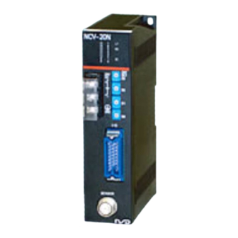
- Page 1 ZEF004472507 ABSOCODER CONVERTER NCV-20NBNMP NCV-20NGNMP NCV-20NBNLW NCV-20NGNLW NCV-20NBNLY NCV-20NGNLY Specifications & Instruction Manual Applicable sensor: MRE-32SP062 MRE-G[ ]SP062 VLS-256PWB VLS-512PWB VLS-1024PW VLS-512PYB VLS-1024PBY VLS-2048PY...
- Page 3 - Be sure to store the controller in designed temperature and humidity CAUTION range, and do not exposed to direct sunlight. - Be sure to consult with NSD when the controller is stored for long - Be sure to handle the controller as industrial waste while periods.
- Page 4 < NCV-20NB (G) NMP (LW, LY) Specifications & Instruction Manual Revision History> * The Document No. appears at the upper right of this manual's cover page. Document No. Date Revision Description ZEF004472500 20, Sep., 2005 1st Edition Japanese document: ZEF004472002 ZEF004472501 19, Oct., 2005 2nd Edition...
-
Page 5: Table Of Contents
CONTENTS 1. SUMMARY ................................1 1-1. Features ................................1 2. CONFIGURATION ..............................2 2-1. Model List ................................3 3. SPECIFICATIONS ..............................5 3-1. Converter Specifications ............................ 5 3-2. ABSOCODER Sensor Specifications ......................... 7 3-3. Extension Sensor Cable Specification ....................... 9 4. -
Page 7: Summary
An origin returning operation is not required. (2) Superior durability NSD's original ABSOCODER is used as the position sensor which features a no-contact construction for excellent durability. This sensor offers problem-free operation, even in environments where it is exposed to vibration, impact shocks, extreme temperatures, oil, and dust. -
Page 8: Configuration
2. CONFIGURATION 1) Converter Connector at cable side (It is included in the External output signal converter.) -Position data MR-25F:Soldered socket -Latch pulse MR-25L:Cover Power -Sensor disconnected Connectors are manufactured Supply by Honda Tsushin Kogyo Co., +24V LTD. Ground External input signal -HOLD 3) Interconnecting sensor cable 2) ABSOCODER sensor... -
Page 9: Model List
2-1. Model List (1) Multi-turn type ABSOCODER Items Models Descriptions Converter NCV-20NBNMP Position data binary output NCV-20NGNMP Position data gray binary output ABSOCODER MRE-32SP062SAC Total number of turns: 32, Servo-mount type, Flat shaft sensor shape MRE-32SP062SBC Total number of turns: 32, Servo-mount type, Key way shaft shape MRE-32SP062FAC Total number of turns: 32, Flange-mount type, Flat shaft... - Page 10 (2) Linear type ABSOCODER Items Models Descriptions 1) Converter Position data binary output NCV-20NBNLW Applicable sensor: VLS-256PWB,VLS-512PWB,VLS-1024PW Position data gray binary output NCV-20NGNLW Applicable sensor: VLS-256PWB,VLS-512PWB,VLS-1024PW Position data binary output NCV-20NBNLY Applicable sensor: VLS-512PYB,VLS-1024PYB,VLS-2048PY Position data gray binary output NCV-20NGNLY Applicable sensor: VLS-512PYB,VLS-1024PYB,VLS-2048PY ABSOCODER [ ]: Detection stroke (Max.
-
Page 11: Specifications
3. SPECIFICATIONS 3-1. Converter Specifications (1) General Specification Items Specifications ± Power supply voltage 24VDCV 10% (including ripple) Power consumption 7W or less 20 M-Ohms or more between external DC power terminals and ground Insulation resistance (by 500 VDC insulation resistance tester) 500 VAC, 60Hz for 1 minute between external DC power terminal and Withstand voltage ground... -
Page 12: Input/Output Specification
(3) Input / Output Specification Items Specifications Input signals HD (Position data HOLD): 1 point Input circuit DC input, photo-coupler insulation Input logic Negative logic ± Rated input voltage 24VDC Input Rated input current 10mA(24VDC) ON voltage 10VDC or more OFF voltage 4VDC or less D0 to D15 (Position data): 16 points... -
Page 13: Absocoder Sensor Specifications
3-2. ABSOCODER Sensor Specifications MRE-32SP062, MRE-G[ ]SP062 Items Specifications MRE-G[ ]SP062 Sensor model MRE-32SP062 [64] [128] [160] [256] [320] Total number of turns Divisions/Turn 2048 1024 409.6 204.8 Total number of divisions 65536(2 Mass 1.5 kg 2° 4° 5° 8° 10°... - Page 14 VLS-[ ]PW Specifications Items VLS-256PWB VLS-512PWB VLS-1024PW Absolute detection range (mm) 1024 Resolution (μm) 7.8125 15.625 31.25 Total number of divisions 32768 Linearity error (mm) 0.05 Max 0.1 Max 0.4 Max Mass (kg) 4.9 or less 7.8 or less 19.6 or less Sliding resistance Permissible mechanical speed (mm/s)
-
Page 15: Extension Sensor Cable Specification
Vinyl chloride mixture Color of sheath Gray Black Usable with moving machine Advantage Extensible for long distances member thanks to excellent flexibility [Remark] Contact your NSD representative when the extension cable combines the standard cable (4P-S) and the robotic cable (4P-RBT). -
Page 16: Dimensions
4. DIMENSIONS 4-1. Converter Units: mm Mounting hole... -
Page 17: Absocoder Sensor
4-2. ABSOCODER Sensor (1) Multi-turn type ABSOCODER Units: mm... - Page 18 Units: mm...
- Page 19 (2) Linear type ABSOCODER Units: mm...
- Page 20 Units: mm...
-
Page 21: Extension Sensor Cable
4-3. Extension Sensor Cable Units: mm 4P-S-0102-[L]/4P-RBT-0102-[L] 4-4. Interconnecting Sensor Cable Units: mm 4P-RBT-0103-[L]... -
Page 22: Installation
5. INSTALLATION The installation conditions and precautions for each of the system components are described in this section. 5-1. Converter Installation Conditions and Precautions -Installation Site (1) Avoid sites where the unit is exposed to direct sunlight. (2) The ambient temperature should never exceed a 0 to 55°C range. (3) The ambient humidity should never exceed a 20 to 90% RH range. -
Page 23: Absocoder Sensor Installation Conditions And Precautions
5-2. ABSOCODER Sensor Installation Conditions and Precautions The installation conditions and precautions for ABSOCODER sensor are described in this section. -Handling of Turn-type ABSOCODER Item Explanation 1) Main unit 2) Cable -Mounting of Turn-type ABSOCODER Item Explanation Precaution 1) Mounting For details regarding mounting dimensions, refer to each sensor dimensions. - Page 24 -Mounting of Turn-type ABSOCODER Item Explanation Precaution 1) Coupling of machine A “direct-link” format will shaft and sensor result in shaft fatigue shaft and / or breakage after long periods. Therefore, be sure to use a coupling device to link the shafts. 2) For gear-type linkage Incorrect gear mounting can result in shaft...
- Page 25 Mounting of Turn-type ABSOCODER Item Explanation Precaution 5) Shaft mounting position -Coupling of Turn-type ABSOCODER Item Explanation Precaution 1) Coupling device The selection of a selection precaution larger coupling than necessary will increase the shaft load which is caused by the mounting error amount.
- Page 26 -Handling of Linear-type ABSOCODER <Multi-pitch & Dual-rod type> Item Explanation 1) ABSOCODER unit 2) Sensor rod 3) Anchor method -Operation Range of Linear type ABSOCODER<Multi-pitch & Dual-rod type> Item Explanation 1) Operation range...
- Page 27 -Mounting of Linear-type ABSOCODER <Multi-pitch and Dual-rod type> Item Explanation 1) Mounting on rod anchor block 2) Mounting bolt positions 2. 3) Mounting conditions 3. The mounting parallelism and squareness should be as shown in the following figures.
-
Page 28: Ce Marking
5-3. CE Marking NCV-20 series conforms to CE Marking (EMC directive), but stands outside scope of the low voltage directive because it is 24 VDC power apparatus. 5-3-1. EMC Directives It is necessary to do CE marking in the customer’s responsibility in the state of a final product. Confirm EMC compliance of the machine and the entire device by customer because EMC changes configuration of the control panel, wiring, and layout. -
Page 29: Wiring
6. WIRING 6-1. Connection between Converter and ABSOCODER Sensor The maximum extension sensor cable length varies according to the ABSOCODER sensor and cable model being used. Please refer to the 3-2 for details. -Wiring Precautions (1) The sensor cable should be clamped as shown in the right figure to prevent excessive tension from being applied to the cable connectors. -
Page 30: Power Supply Connection
6-2. Power Supply Connection The power supply should be connected as described below: (1) Power Supply -The rush current is 10A(rush time of 20ms), so select the power supply after due consideration. Over current Power +24VDC Choose the capacity of the power supply over Supply protector double of power consumption of converter. -
Page 31: Input / Output Connector Connection
6-3. Input / Output Connector Connection Lead wires should be soldered to pins of the connector according to the I/O chart below. Input / Signal Names Descriptions Output NCV-20NBNMP: (LSB) Output the position data by16 bit of binary code. NCV-20NGNMP: Output the position data by16 bit of gray binary code. - Page 32 ●I/O Circuit Converter internal circuit Input/output circuit is isolated from power supply and internal circuitry by photo-coupler. Use a Class 2 power supply for the input/output external power supply.
-
Page 33: Nomenclature
7. NOMENCLATURE 7-1. Part Identification Monitor LEDs -Position data output indicator -Sensor disconnection indicator -Latch pulse indicator -HOLD input indicator Power terminal block -M4 screw Current position value setting switch I/O connector Sensor connector 7-2. Function and Name of Display and Setting Area Rear face LED function for monitor Switch... -
Page 34: Operation
8. OPERATION 8-1. Operation Sequence START Function selector switch setting Designate the following setting by a switch which is at rear face of the converter. -------- Refer to section 8-2, 8-3. (1) Position data "increase direction" setting (2) Position data reading setting Converter mounting -------- Refer to section 5-1. -
Page 35: Position Data "Increase Direction" Setting
8-2. Position Data "Increase Direction" Setting The position data increases or decreases according to the ABSOCODER sensor's rotative direction (travel direction). The direction in which the position data increases is specified by a switch on the converter's rear face. Switch setting Increase Switch setting Alteration of the position data... -
Page 36: Position Data Reading Setting
8-3. Position Data Reading Setting (1) Function setting switch list The following two position data reading formats are available: 1) Latch pulse (LP) format…Reads position data which is updated regularly in synchronization with a latch pulse output signal from the converter. 2) HOLD (HD) format…Reads position data while position data updates are stopped by a HOLD input signal. -
Page 37: Position Data Reading By Lp Output
(2) Position data reading by LP output Position data reading is synchronized with the LP output signal from the converter. Either high-speed or low-speed reading can be selected. ●High-speed reading When high-speed reading is selected, the position data output stabilizes at the trailing edge of the LP output signal. - Page 38 ●Low-speed reading (at LP=HIGH) When low-speed reading (at LP=HIGH) is selected, the position data output stabilizes when the LP output signal is HIGH. The position data should be read at that time. Position data update Switch setting cycle 12.8ms 12.8ms 3.2ms 6.4ms 25.6ms...
-
Page 39: Position Data Reading By Hold (Hd) Input
(3) Position data reading by HOLD (HD) input The HD input signal is used to HOLD position data outputs from the host controller. Either of the following 2 position data HOLD formats can be selected. ●Transparent format Position data output updating is stopped by an HD input signal from the host controller (PLC, etc.). The position data should be read at that time. -
Page 40: Current Position Setting
8-4. Current Position Setting The current position setting function changes the converter's position data output to a value that corresponds to the machine's current position. The position data can be changed to any desired value by using the rotary switch on the control panel. If an extension sensor cable is being used, the cable must be connected when performing the current position setting function. -
Page 41: For Gray Binary Code Output
(2) For gray binary code output <Current position setting procedure> 1) Secure the sensor to the machine, then move the machine to the desired position. 2) Obtain the position data that corresponds to the machine's current position. 3) Convert the position data obtained at step 2) above to gray binary code. 4) Use the control panel's rotary switches (in the D0 to D3 order) to specify monitor LED values that match the value converted at step 3) above. -
Page 42: Maintenance And Inspections
“HD”(the external input signal) is ON. The wiring of the output signal has problems. Repair the wiring. If the troubleshooting procedures described above fail to solve the problem, the sensor or converter may be defective. In this case, please contact your NSD representative. - Page 44 Manufacturer NSD Corporation 3-31-28, OSU, NAKA-KU, NAGOYA, JAPAN 460-8302 Distributor NSD Trading Corporation 3-31-23, OSU, NAKA-KU, NAGOYA, JAPAN 460-8302 Phone: +81-52-261-2352 Facsimile: +81-52-252-0522 URL: www.nsdcorp.com E-mail: foreign@nsdcorp.com Copyright©2020 NSD Corporation All rights reserved.
Need help?
Do you have a question about the ABSOCODER NCV-20NBNMP and is the answer not in the manual?
Questions and answers