
Subscribe to Our Youtube Channel
Related Manuals for NSD ABSOCODER NCV-30HBNL8


Summary of Contents for NSD ABSOCODER NCV-30HBNL8
- Page 1 ZEF004571309 For Iron and Steel Industry ABSOCODER CONVERTER NCV-30HBNL8 Specifications & Instruction Manual Applicable sensor: VLS-8SM...
-
Page 3: General Safety Rules
- Be sure to store the controller in designed temperature and humidity CAUTION range, and do not exposed to direct sunlight. - Be sure to consult with NSD when the controller is stored for long - Be sure to handle the controller as industrial waste while periods. - Page 4 REVISION HISTORY The Document No. appears at the upper right of this manual's cover page. Document No. Date Revision Description ZEF004571300 26, Sep., 2011 1st Edition Japanese document: ZEF004571001 ZEF004571301 7, Oct., 2011 2nd Edition Japanese document: ZEF004571002 ZEF004571302 7, Feb., 2012 3rd Edition Japanese document: ZEF004571002 ZEF004571303...
- Page 5 - MEMO -...
-
Page 6: Table Of Contents
CONTENTS 1. SUMMARY ..........................1 1-1. Features ................................1 1-2. Limitations ................................2 2. CONFIGURATION ........................3 3. SPECIFICATIONS ........................5 3-1. Converter Specifications ............................ 5 3-2. ABSOCODER Sensor Specifications ......................... 8 3-3. Extension Sensor Cable Specification ......................10 4. DIMENSIONS ........................11 4-1. - Page 7 8. OPERATION .......................... 27 8-1. Operation Sequence ............................27 8-2. Settings of the Function Setting Switch ......................28 8-3. Position Data "Increase Direction" Setting ....................... 30 8-4. Position Data Reading Setting ......................... 31 8-4-1. Position Data Reading by LP output ....................31 8-4-2.
-
Page 8: Summary
1-1. Features (1) Superior durability NSD's original ABSOCODER is used as the position sensor which features a no-contact construction for excellent durability. (2) Compact design The unit's outside dimensions (39(W) x 155(H) x 93(D)) were miniaturized, and the shape of case is a bookshelf type. -
Page 9: Limitations
1-2. Limitations Important Cautions concerning power-off and error occurrence If the sensor moves while the converter power is OFF or when an error is present, it mightn’t detect accurate machine positions thereafter. The zero position setting should be done after turning ON the power supply or clearing the error. For setting details, refer to "8-7. -
Page 10: Configuration
2. CONFIGURATION Indicates the configuration of NCV-30H. Contact your NSD representative for details of ABSOCODER sensor and the extension sensor cable. ●Connection configuration 1) Converter Connector at cable side (It is included in the External output signal converter.) -Position data... - Page 11 B: Standard connector VLS-8SM14-[1]FB[2][L] Linear type type (NJW-2012PM8, manufacturer: ABSOCODER Nanaboshi Electric Mfg.Co,Ltd.) sensor Contact your NSD representative for VLS-8SM14 and VLS-8SM14S. Flange-mount R: Crimping terminals (R1.25-4) VLS-8SM14S-[1]FB[2][L] type Z: No connector [L]: Interconnecting sensor cable length (m): 2, 5,10, 20...
-
Page 12: Specifications
3. SPECIFICATIONS 3-1. Converter Specifications (1) General Specification Items Specifications ± Power supply voltage 24VDC 10% (including ripple) Power consumption 10W or less 20 M-Ohms or more between external DC power terminals and ground Insulation resistance (by 500 VDC insulation resistance tester) Withstand voltage 500 VAC, 60Hz for 1 minute between external DC power terminals and ground 20m/s... -
Page 13: Performance Specification
(2) Performance Specification Items Specifications Converter model NCV-30HBNL8 Applicable sensor VLS-8SM20 VLS-8SM14 VLS-8SM14S Resolution 1μm (8.192 mm / 8192 divisions) Position detection format Semi-absolute format Standard pitch x number of pitches Total number of divisions (8192 divisions (2 ) x max. 2048 pitches) Binary code output: 24-bit Output code Sign magnitude code: 23-bit ( SIGN output: 1-bit) -
Page 14: Input/Output Specification
(3) Input / Output Specification Items Specifications (Position data HOLD): 1 point Input signals ZPS (Zero point setting): 1 point CLR (Error clear): 1 point Input circuit DC input, photo-coupler isolation Input logic Negative logic Rated input voltage 12 to 24VDC (10.8 to 26.4VDC) Input Rated input current 10mA(24VDC) -
Page 15: Absocoder Sensor Specifications
3-2. ABSOCODER Sensor Specifications (1) VLS-8SM20 Items Specifications Model VLS-8SM20 Max. detection stroke 350 mm Absolute detection range 8.192 mm Resolution 1μm(8.192mm/8192) Linearity error Customer's Special Specifications Head 4.5+0.15 x [cable length(m)] kg Mass 0.4+0.0025 x [stroke (mm)] kg Sliding resistance 69 N or less (7kgf or less) Permissible mechanical speed 1000 mm/s... - Page 16 (2) VLS-8SM14, VLS-8SM14S Items Specifications Model VLS-8SM14 VLS-8SM14S Max. detection stroke 200 mm Absolute detection range 8.192 mm Resolution 1μm(8.192mm/8192) Linearity error Customer's Special Specifications Head 1.1+0.07 x [cable length(m)] kg 0.8+0.07 x [cable length(m)] kg Mass 0.0012 x ([rod length (mm)] kg Sliding resistance 15 N or less (1.5kgf or less) Permissible mechanical speed...
-
Page 17: Extension Sensor Cable Specification
Color of sheath Dark brown Blue Black Heat treatment and Extensible for long Advantage Superior flexibility; ideal for moving place flexible; ideal for distances moving place [Remark] Contact your NSD representative when the extension cable combines different types of cables. -
Page 18: Dimensions
4. DIMENSIONS 4-1. Converter Units: mm Mounting hole DIN rail... -
Page 19: Absocoder Sensor
4-2. ABSOCODER Sensor (1) VLS-8SM20-[ ]FA[ ] (Flange-mount type) Units: mm (2) VLS-8SM20-[ ]LA[ ] (Base-mount type) - Page 20 (3) VLS-8SM14-[ ]FB[ ] (Flange-mount type) Units: mm (4) VLS-8SM14S-[ ]LB[ ] (Flange-mount type)
-
Page 21: Extension Sensor Cable
4-3. Extension Sensor Cable (1) 3S-S-0144-[L] / 3S-RBT-0144-[L] / 3S-URT-0144-[L] Units: mm NOTE: [L] is given in terms of meter. (2) 3S-S-4344-[L] / 3S-RBT-4344-[L] / 3S-URT-4344-[L] NOTE: [L] is given in terms of meter. (3) 3S-HRT-5152-[L] NOTE: [L] is given in terms of meter. (4) 3S-S-0190-[L] / 3S-RBT-0190-[L] / 3S-URT-0190-[L] NOTE: [L] is given in terms of meter. - Page 22 (5) 3S-S-9044-[L] / 3S-RBT-9044-[L] / 3S-URT-9044-[L] Units: mm NOTE: [L] is given in terms of meter. (6) 3S-HRT-9052-[L] NOTE: [L] is given in terms of meter. (7) 3S-S-9090-[L] / 3S-RBT-9090-[L] / 3S-URT-9090-[L] NOTE: [L] is given in terms of meter. (8) 3S-HRT-9090-[L] NOTE: [L] is given in terms of meter.
-
Page 23: Installation
5. INSTALLATION 5-1. Converter Installation Conditions and Precautions When installing the converter, the following conditions and precautions should be observed. -Installation Site (1) Avoid sites where the unit is exposed to direct sunlight. (2) The ambient temperature should never exceed a 0 to 55°C range. (3) The ambient humidity should never exceed a 20 to 90% RH range. -
Page 24: Absocoder Sensor Installation Conditions And Precautions
Do not use a floating joint. Floating joint Shielding plate (3) When the cable port is exposed, a shielding plate should be installed as shown in the right figure. Contact your NSD representative for details of the installation conditions and precautions for ABSOCODER sensor. -
Page 25: Ce Marking
5-3. CE Marking NCV-30H Series conforms to CE Marking (EMC directive), but stands outside scope of the low voltage directive because it is 24 VDC power apparatus. 5-3-1. EMC Directives It is necessary to do CE marking in the customer’s responsibility in the state of a final product. Confirm EMC compliance of the machine and the entire device by customer because EMC changes configuration of the control panel, wiring, and layout. -
Page 26: Restrictions
5-3-4. Restrictions The I / O cable must be under 30m from the host controller to the converter. The wiring should be surely secured. [Reference] It may be improved when clamp ferrite core is added to the power supply cable, sensor cable, and I/O cable when it operates faultily by the influence from the peripheral device. -
Page 27: Wiring
6. WIRING 6-1. Connection between Converter and ABSOCODER Sensor The length of the extendable cable has a limitation depending on the models of ABSOCODER sensor and sensor cable. For more details, refer to “3-2. ABSOCODER Sensor Specifications ". ●Wiring precautions The sensor cable should be clamped as shown in the right figure to prevent excessive tension from being applied to the cable connectors. -
Page 28: Connection Configure Example Of The Sensor Cable
6-1-1. Connection Configure Example of the Sensor Cable Indicates the ABSOCODER sensor cable connection example when connecting by the standard connector or the crimping terminal. ● In the case of connecting by using connectors Converter Extension sensor cable ABSOCODER sensor... - Page 29 ● In the case of connecting by using crimping terminals ABSOCODER sensor Converter Extension sensor cable Crimping Crimping Crimping terminal (R1.25-4) terminal terminal (R1.25-4) (R1.25-4) NSD special cable NSD special cable ABSOCODER sensor Wire color Wire color Wire color Wire color Signal name Wire color Signal name Wire color...
-
Page 30: Power Supply Connection
6-2. Power Supply Connection The power supply should be connected as described below: (1) Power Supply -The rush current is 10A(rush time of 20ms), so select the power supply after due consideration. Over current Power +24VDC Choose the capacity of the power supply over Supply protector double of power consumption of converter. -
Page 31: Input / Output Connector Connection
6-3. Input / Output Connector Connection 6-3-1. Pin arrangement of the I/O Connector Input / Signal Names Descriptions Output NCV-30HBNL8 Output the position data by 24-bit of binary code. D0 : LSB(Least Significant Bit) D23 : MSB(Most Significant Bit) Position data Output *: 24-pin outputs SIGN signal when selecting the sign magnitude code for the position data output format. -
Page 32: I/O Circuit
●Pin arrangement Connector model: MR-34LF Viewed from the soldered terminals on the rear side of the connector. 6-3-2. I/O Circuit NCV-30 internal circuit Load Load External power supply 12 to 24VDC DC-DC converter (isolation type) HD,ZPS,CLR Input/output circuit is isolated from power supply and internal circuitry by photo-coupler. *: Use a Class 2 power supply for the input / output external power supply. -
Page 33: Nomenclature
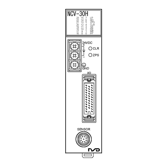
7. NOMENCLATURE 7-1. Part Identification Monitor LEDs Error clear switch Power terminal block -M4 screw Zero point setting switch I/O connector Sensor connector 7-2. Function and Name of Display and Setting Area Function setting switch Monitor LEDs Status monitor (Rear face) : Indication of latch pulse output NCV-30H LP signal is constantly “HIGH level”... -
Page 34: Operation
8. OPERATION 8-1. Operation Sequence START Function selector switch setting Designate the following setting by a switch which is at rear face of the converter. -------- Refer to section 8-2 to 8-5. (1) Position data "increase direction" setting (2) Position data reading setting Converter mounting -------- Refer to section 5-1. -
Page 35: Settings Of The Function Setting Switch
8-2. Settings of the Function Setting Switch The following two position data reading formats are available: 1) Latch pulse ( LP ) format…Reads position data which is updated regularly in synchronization with a latch pulse output signal from the converter. 2) HOLD ( HD ) format…Reads position data while position data updates are stopped by a HOLD input signal. - Page 36 The DIP switch settings are shown below. (Position data increase direction) Refer Position data increase ON 1 2 3 4 5 6 7 8 (Factory setting) to 30P. direction setting ON 1 2 3 4 5 6 7 8 (Position data update cycle) 0.2ms ON 1 2 3 4 5 6 7 8 (Factory setting)
-
Page 37: Position Data "Increase Direction" Setting
8-3. Position Data "Increase Direction" Setting The position data increases or decreases according to the ABSOCODER sensor's rod travel direction. The direction in which the position data increases is specified by a switch on the converter's rear face. Switch setting Increase direction Switch setting Alteration of the position data... -
Page 38: Position Data Reading Setting
8-4. Position Data Reading Setting 8-4-1. Position Data Reading by LP output Position data reading is synchronized with the LP output signal from the converter. Either high-speed or low-speed reading can be selected. (1) High-speed reading When high-speed reading is selected, the position data output is updated at the leading edge of the LP output signal. - Page 39 (2) Low-speed reading (at LP=LOW) When low-speed reading (at LP =LOW) is selected, the position data output is updated when the LP output signal is HIGH. It stabilizes when the LP output signal is LOW, so the position data should be read at that time.
-
Page 40: Position Data Reading By Hold (Hd) Input
8-4-2. Position Data Reading by HOLD (HD) Input The HOLD input signal is used to HOLD position data outputs from the host controller. Either of the following two position data HOLD formats can be selected. (1) Transparent format Position data output updating is stopped by an HOLD input signal from the host controller (PLC, etc.). The position data should be read at that time. - Page 41 (2) PC synchro format Position data output updating occurs when the HOLD input signal status changes (leading edge or trailing edge), and is not synchronized with the LP output signal. Position data reading should be performed after waiting period "t3" following the HOLD input signal status is changed by the host controller (PLC, etc.).
-
Page 42: Position Data Output Format Setting
8-5. Position Data Output Format Setting Select the position data output format from the binary code, sign magnitude code, or minus zone “0” output. Binary code output: Outputs 24-bit of binary code. Sing magnitude code output: D23 output changes to minus sign output. The minus sign output is ON when the machine position travels to the minus side. -
Page 43: System Ready Signal
8-6. System Ready Signal The system ready signal indicates that the normal position data is output from the converter. The signal is “LOW level” when ABSOCODER sensor and converter operate normally. For your safety, read the position data when the system ready signal is “LOW level”. The system ready signal is “HIGH level”... -
Page 44: Zero Point Setting
8-7. Zero Point Setting A “zero point setting” refer to an operation in which the position data ( D0 to D23 ) is set to “0”. To set the zero point, move the ABSOCODER sensor’s rod to the zero point position. After that, execute by using either the “ZPS”... -
Page 45: Timing Of The Zero Point Setting When Using A Latch Pulse Signal
8-7-2. Timing of the Zero Point Setting when Using a Latch Pulse Signal Indicates the timing of the zero point setting when using a latch pulse signal. Data after setting the zero point Position data output “0” OFF (H) Zero point setting input ON (L) ts: Position data update cycle Check the position data update cycle setting of the function setting switch. -
Page 46: Timing Of The Zero Point Setting When Using A Hold Signal
8-7-3. Timing of the Zero Point Setting when Using a HOLD Signal Indicates the timing when setting either transparent format or PC synchro format of HOLD input. (1) Transparent format In the case of setting the zero point during HOLD input is ON (L) by transparent format, turning OFF(H) HOLD input allows outputting the position data after setting the zero point. -
Page 47: Error Clear
8-8. Error Clear Describes the error clear procedure in this chapter. (1) Using the error clear button on the front panel Press the error clear button on the front panel. Error clear button... - Page 48 (2) Input the error clear signal Input the error clear signal ( CLR ). Important The error clear input must be ON 20ms or more. The error clear signal must be turned OFF after clearing the error. Indicates the timing of system ready output when inputting the error clear. For your safety, read the position data when the system ready signal is “LOW level”.
-
Page 49: Inspections
9. INSPECTIONS The inspection should be conducted once every 6 months to a year. Any inspected items which do not satisfy the criteria shown below should be repaired. Inspection Inspection Description Criteria Remark item Power Measure the voltage at the power supply terminal Within 21.6 to 26.4VDC Tester supply... -
Page 50: Troubleshooting
10. TROUBLESHOOTING The causes and corrective actions for errors that may occur during NCV-30H operation are described below. 10-1. Display and Countermeasure when an Error Occurred NCV-30H has LED for the error monitor. Error contents are checked by LED light. Refer to the following list and implement appropriate countermeasures. - Page 51 ● Other error contents Error contents Probable cause Error cancel procedures Coupling of ABSOCOER sensor rod and the machine is loose. Secure the coupling / mounting. Zero point deviation ABSOCODER sensor mounting is loose. Check the signal status. “ ZPS ”(the external input signal) is ON. LP output signal and position data reading timing are improper.
-
Page 52: Output State When Occurring An Error
10-2. Output State when Occurring an Error Indicates the state of output signal when occurring an error. Output Position data output Latch pulse output System ready output Item D0 to D23 “SE” LED is ON Sensor disconnected error “SE” LED is blinking -5V power supply error The data before “DE”... - Page 53 - MEMO -...
-
Page 54: Absocoder Sensor Check Lists
10-4. ABSOCODER Sensor Check Lists ● Applicable ABSOCODER sensor models VLS-8SM20 VLS-8SM14 VLS-8SM14S ● Connection configuration ABSOCODER sensor Extension sensor cable Converter ● Connector appearance and pin position View View A1, B1 ● Connector pin position and standard coil resistance ranges (at 25℃) Check position Standard coil resistance [Ω] A1, A2, B1, B2... - Page 55 Extension sensor cable resistance value The resistance value of the NSD special cable is 0.2Ω/m (loop resistance). Consider resistance variations due to temperature, which, relative to the standard temperature C), increases 0.4% when the temperature rises 1 C and decreases 0.4% when the...
- Page 56 Manufacturer NSD Corporation 3-31-28, OSU, NAKA-KU, NAGOYA, JAPAN 460-8302 Distributor NSD Trading Corporation 3-31-23, OSU, NAKA-KU, NAGOYA, JAPAN 460-8302 Phone: +81-52-261-2352 Facsimile: +81-52-252-0522 URL: www.nsdcorp.com E-mail: foreign@nsdcorp.com Copyright©2020 NSD Corporation All rights reserved.
Need help?
Do you have a question about the ABSOCODER NCV-30HBNL8 and is the answer not in the manual?
Questions and answers