Table of Contents
Advertisement
Quick Links
Advertisement
Table of Contents

Related Manuals for Getinge Applikon my-Control


Summary of Contents for Getinge Applikon my-Control
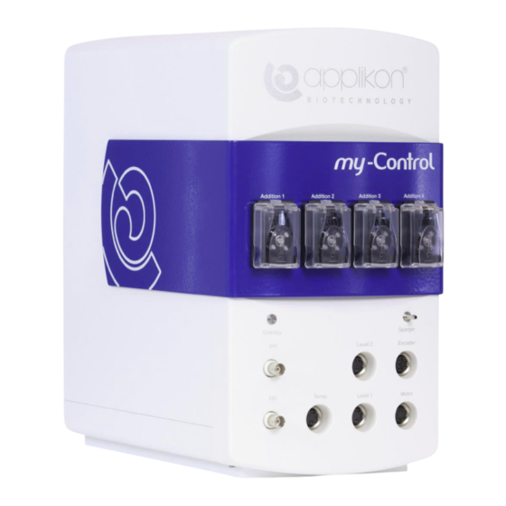
- Page 1 Hardware Manual my-Control for MiniBio Reactors 250, 500, 1000 mL...
-
Page 2: Table Of Contents
CONTENTS TABLE OF CONTENTS Safety ................................. 4 Safety Symbols ..........................4 Safety Warnings ..........................5 EU Declaration of Conformity ......................8 General ..............................9 Introduction ............................9 The User Interface ..........................9 Related Manuals ..........................10 The my-Control ............................11 Front view of the my-Control ...................... - Page 3 CONTENTS MiniBio Reactor Assembly 1000 ml ....................39 6.3.1 General Reactor Specifications ..................39 6.3.2 Head Plate Specifications ....................40 6.3.3 Required Space in Autoclave ................... 40 6.3.4 Bioreactor Assembly 1000 ml ..................41 Stirrer Drive and Stirrer Assembly ....................43 6.4.1 Impellers ...........................
-
Page 4: Safety
SAFETY 1 SAFETY SAFETY SYMBOLS The following symbols are used on the equipment and in this manual. WARNING Important issue concerning personnel health and device safety. Refer to this manual. WARNING Risk of electrical shock hazard. WARNING Hot surface. INFORMATION Additional information. -
Page 5: Safety Warnings
SAFETY SAFETY WARNINGS GENERAL • This equipment has been designed in accordance with EN61010-1 "Safety Requirements for Electrical Equipment for Measurement, Control and Laboratory Use", and has been supplied in a safe condition. • The Hardware manual contains information and warnings, which have to be followed by the user to ensure safe installation, operation and to retain the equipment in safe condition. - Page 6 SAFETY WARNING Risk of damaging the equipment. • In most cases, one or more pumps are installed in the my-Control. • Application of damaged tubes may result in fluid leaking into the pump drive. • Verify the tube quality inside the pump head before every fermentation run. •...
- Page 7 SAFETY WARNING Sensor is fragile. Handle with care! • For measuring the dissolved oxygen concentration in the bioreactor, the LumiSens Optical dO2 sensor is used. This sensor is fragile; the replaceable LumiSens sensor tip is made of glass and can break easily.
-
Page 8: Eu Declaration Of Conformity
L. van Mierlo Delft, Digitally signed by Director QRC Lukas van Mierlo The Netherlands Date: 2023.03.20 12:40:57 +01'00' Applikon Biotechnology B.V. Heertjeslaan 2 Tel. +31 (0)10 208 35 55 2629 JG Delft info.applikon@getinge.com The Netherlands www.getinge.com Hardware Manual my-Control MiniBio... -
Page 9: General
GENERAL 2 GENERAL INTRODUCTION The Applikon autoclavable MiniBio Reactor Systems basically consist of the following parts: • an autoclavable MiniBio Reactor with the appropriate auxiliaries such as a stirrer assembly, sensors, an aeration assembly, etc. • a my-Control bio controller for measurement and control of process variables (like pH, temperature, DO, level and stirrer speed) with corresponding controller outputs in order to keep process conditions at set point. -
Page 10: Related Manuals
GENERAL After switching on the power of the my-Control and invoking the Web UI with the Internet browser, the my- Control displays its Home Screen. Example of the Home Screen in View mode (no user is logged in, control loops are “Idle”): Use the mouse pointer to press the virtual buttons at the Web UI of the my-Control. -
Page 11: The My-Control
THE my-CONTROL 3 THE my-CONTROL The my-Control is a full-size biocontroller dedicated to controlling a bioreactor process. It contains: • Fixed and adaptive PID control for pH, dO and Temperature • Stirrer Speed control • Foam and/or Level control • Additional (freely configurable) measuring channels / PID control loops, such as: - (max. -
Page 12: Rear View Of The My-Control
THE my-CONTROL REAR VIEW OF THE my-CONTROL At the rear of the control cabinet, the following connections can be found: Power Supply section The Power Supply Section of the my-Control contains: • Mains Cable Connector for: 220-240 VAC / 50 Hz or 100-120 VAC / 60 Hz. -
Page 13: Modules To Be Mounted Inside The My-Control
THE my-CONTROL Positions for Optional I/O Connections and Devices • Thermo Electric Condenser Connection Connection for condenser with Thermo Electric cooler. • Connection for Temperature Control Actuators Actuator connection for heating and cooling: Thermo Electric element or heating blanket and cooling valve. •... -
Page 14: Colors Of The Front Panel
THE my-CONTROL COLORS OF THE FRONT PANEL By default, the my-Control comes with a silver front panel. Other front panel colors are available on demand. Ordering numbers of my-Controls with different colors: Part # Description Part # Description Z310210130 Front Panel Silver V2 Z310210135 Front Panel Light Blue V2 Z310210131... -
Page 15: Actuator Control
THE my-CONTROL ACTUATOR CONTROL 3.6.1 DIGITAL ACTUATORS VERSUS CONTINUOUS ACTUATORS Discrete (digital) actuators such as valves are controlled in a “Pulse-Width Modulated” manner (PWM): • within a predefined “cycle time”, the output (Actuator) is switched on during the “On-time” and off during the rest of the cycle. -
Page 16: Sensor Input Specifications
THE my-CONTROL SENSOR INPUT SPECIFICATIONS The applied sensor input amplifiers have the following specifications. 0 pH … 14 pH pH amplifier: Range: Accuracy: ± 0.01 pH Ω > 10 Resolution: 0.01 Temperature amplifier: Type: Pt-100 (3-wire type) 0 ºC … +150 ºC Range: Accuracy: ±... -
Page 17: Analog And Digital I/O Connections
THE my-CONTROL ANALOG AND DIGITAL I/O CONNECTIONS The analog and digital I/O connections are located at the rear of the my-Control: Analog Inputs The (max. 4) analog input connectors contain four pins: • Pin 1 = Analog input • Pin 2 = Ground •... -
Page 18: Environmental Conditions
THE my-CONTROL ENVIRONMENTAL CONDITIONS The my-Control may be used at locations with the following environmental conditions: • indoor • Altitude: up to 2000 m • Temperature: 4 °C to 40 °C • Relative humidity: maximum 80 % for temperatures up to 31 °C, decreasing linearly to 50 % relative humidity at 40 °C •... -
Page 19: Internal Actuators
INTERNAL ACTUATORS 4 INTERNAL ACTUATORS The my-Control may be equipped with different internal actuators for aeration and addition of liquid: • Solenoid valve with tuning valve per gas inlet line (nitrogen, air, oxygen and carbon dioxide) • 1-channel or 3-channel mass flow controller •... -
Page 20: Mass Flow Controllers
INTERNAL ACTUATORS MASS FLOW CONTROLLERS Two types of mass flow controllers are used in the my-Control. • 3-Channel Mass Flow Controller (for controlling the flow of three individual gasses) • 1-Channel Mass Flow Controller (for controlling the flow of one gas only) Both Mass Flow Controllers (MFC) are applied for bioreactor aeration. -
Page 21: Connection For Sparging
INTERNAL ACTUATORS MFC Ordering Information: Z310212120* 1-Channel MFC Assembly for my-Control Z310212320* 3-Channel MFC Assembly for my-Control Z310212110* Mounting Kit for 1-Channel MFC my-Control Z310212310* Mounting Kit for 1-Channel MFC my-Control When one or more MFCs must be added to an existing my-Control, one of the cables below must be ordered: VBL2080321* Cable Act. -
Page 22: Tubing Pump Assembly
INTERNAL ACTUATORS TUBING PUMP ASSEMBLY WARNING Risk of damaging the equipment. • Application of damaged tubes may result in fluid leaking into the pump drive. • Verify the tube quality inside the pump head before every new cultivation. • Do not use the tubing pump drives for other purposes than displacement of fluids (or gas). -
Page 23: Microbore Tubing Set With Luer Lock Connectors
INTERNAL ACTUATORS 4.4.1 MICROBORE TUBING SET WITH LUER LOCK CONNECTORS Since the MiniBio Reactors are equipped with Luer Lock connections at the addition and sample ports, a Microbore Tubing Set with Luer Lock connectors has been prepared. Z811000271 MiniBio Tubing Set Microbore The Tubing Set consists of: 5 pieces of tubing with a length of 100 mm and 10 pieces of tubing with a length of 750 mm. -
Page 24: Pump Tubing Connection
INTERNAL ACTUATORS PUMP TUBING CONNECTION The liquid addition line between storage vial and MiniBio reactor can be realized according to the image below: The rotor in the pump head turns counterclockwise. Make sure that the pump tubing is configured accordingly! EXTERNAL PUMPS Z310214030 Analog Output, License and Pump Cable MiniFlex 7525-20... -
Page 25: External Actuators
EXTERNAL ACTUATORS 5 EXTERNAL ACTUATORS HEATING BLANKET The heating blanket is wrapped around the glass bioreactor. The maximum temperature of the outer surface is limited (by thermal cut-off) to 80 °C. Maximum medium temperature that can be reached by heating with a heating blanket: 60 °C (or higher, depending on the reactor size). -
Page 26: Thermo Electric Element For Temperature Control
EXTERNAL ACTUATORS THERMO ELECTRIC ELEMENT FOR TEMPERATURE CONTROL The temperature in the 250 and 500 ml MiniBio reactor can be controlled by using the Thermo Electric Heater / Cooler Assembly. Specifications of the Thermo Electric Element: Nominal power consumption: 80 W. Medium Heating Capacity: 18 to 37 °C: <... -
Page 27: Micro Valve
EXTERNAL ACTUATORS MICRO VALVE The Micro Valve is used for accurate “continuous” liquid additions at the micro scale (1 – 100 ml/hour) in the pharmaceutical and biotechnological industries. It is suitable for additions of weak acids and bases or pH-neutral solutions. pH range of applicable solutions: pH = 4 ... -
Page 28: Valve Assembly
EXTERNAL ACTUATORS 5.3.1 VALVE ASSEMBLY Exploded View of the Micro Valve assembly: When assembling the micro valve, ensure that no foreign bodies are inadvertently included 1. The Dispensing Valve (Body) has been affixed to the Adapter M8x1 (with glue) Mount the Adapter M8x1 with O-Ring and Valve Body in one of the M8x1 ports in the reactor head plate. -
Page 29: Micro Valve Setup
EXTERNAL ACTUATORS 5.3.3 MICRO VALVE SETUP The image below shows the micro valve liquid addition setup. The valve operates optimally with a differential pressure of 0.5 barg. The micro valve is controlled by the my-Control. The liquid feed is pre-filtered using 0.45µm as indicated in the image below. Hardware Manual my-Control MiniBio... -
Page 30: Flow Rate As Function Of On / Off Time Parameters
EXTERNAL ACTUATORS 5.3.4 FLOW RATE AS FUNCTION OF ON / OFF TIME PARAMETERS The liquid addition rate depends on the opening time duration in relation to the cycle time of the Micro Valve. The time based parameters for controlling liquid flow rate are accessible and can be set at the HMI of the my-Control. -
Page 31: Cleaning
EXTERNAL ACTUATORS 5.3.5 CLEANING The valve should be cleaned immediately after completing the fermentation or cultivation. Flush the valve with sterile demineralized and filtered (0.45 micron) water with ON time = 5000 ms and OFF time = 10 ms. Flush the valve for at least 10 minutes. 5.3.6 AUTOCLAVING The micro valve is autoclavable at a temperature of approx. -
Page 32: Reactors And Auxiliaries
REACTORS AND AUXILIARIES 6 REACTORS AND AUXILIARIES The 250 and 500 ml MiniBio Reactors and their Auxiliaries are represented by the image below. The 1000 ml MiniBio Reactor is an integrated assembly of stand and reactor and is described in the relevant section about MiniBio Reactor Assembly 1000 ml. -
Page 33: Minibio Reactor Assembly 250 Ml
REACTORS AND AUXILIARIES MINIBIO REACTOR ASSEMBLY 250 ML The 250 ml MiniBio Reactor consists of three major parts: V3LP070501 Stand for 250ml MiniBio Reactor M2 V3LP070701 Bioreactor Assembly 250ml MiniBio M2 V3MP078071 Autoclave Frame for 250ml MiniBio Reactor (frame for autoclaving the reactor) The three parts are presented in the images below: Autoclave Frame 250ml MiniBio Reactor Assembly 250ml... -
Page 34: 250Ml Head Plate Specifications
REACTORS AND AUXILIARIES 6.1.2 250ML HEAD PLATE SPECIFICATIONS The head plate comes with welded inserts for: • Temperature measurement (thermometer pocket) • Sparging and sampling • Additions or overlay Port # Description Sensor / Condenser Port M12 x 1 Sensor / Condenser Port M12 x 1 Sensor / Condenser Port M12 x 1 Universal Port M8x1 Universal Port M8x1... -
Page 35: Bioreactor Assembly 250 Ml
REACTORS AND AUXILIARIES 6.1.4 BIOREACTOR ASSEMBLY 250 ML The 250 ml bioreactor consists of the following parts: Part # Description V3MP072501 Vessel Dished Bottom 250ml V3MP071851 Lock Ring for Top Plate 250ml V3MP071811 Ring M80x2 for Top Plate 250ml V3MP071031 Level Sensor Bush V3KP070141 Holder Ring 4x Addition Bottle V3KP070121... -
Page 36: Minibio Reactor Assembly 500 Ml
REACTORS AND AUXILIARIES MINIBIO REACTOR ASSEMBLY 500 ML The 500 ml MiniBio Reactor consists of three major parts: V3LP070551 Stand for 500ml MiniBio Reactor M2 V3LP070721 Bioreactor Assembly 500ml MiniBio M2 V3MP078081 Autoclave Frame for 500ml MiniBio Reactor (frame for autoclaving the reactor) The three parts are presented in the images below: Autoclave Frame 500ml MiniBio Reactor Assembly 500ml... -
Page 37: Head Plate Specifications
REACTORS AND AUXILIARIES 6.2.2 HEAD PLATE SPECIFICATIONS The head plate comes with welded inserts for: • Temperature measurement (thermometer pocket) • Sparging and sampling • Additions or overlay Port # Description A1 (Luer Lock) Sparger Pipe B1 (Luer Lock) Addition or Overlay Pipe B2 (Luer Lock) Addition or Overlay Pipe B3 (Luer Lock) -
Page 38: Bioreactor Assembly 500 Ml
REACTORS AND AUXILIARIES 6.2.4 BIOREACTOR ASSEMBLY 500 ML The 500 ml bioreactor consists of the following parts: Part # Description V3MP075001 Vessel Dished Bottom 500 ml V3KP070161 Holder Ring 4x Addition Bottle V1S4ARP152 Silicone O-Ring ID 82.22x2.62 V1S4ARP146 Silicone O-Ring ID 66.34x2.62 V3MP071951 Ring for Top Plate 500ml V3MP071981 Lock Ring for Top Plate 500ml V3KP070131... -
Page 39: Minibio Reactor Assembly 1000 Ml
REACTORS AND AUXILIARIES MINIBIO REACTOR ASSEMBLY 1000 ML The 1000 ml MiniBio Reactor consists of one assembly: Z611100020 MiniBio Reactor 1000 ml V2 See the images below: 6.3.1 GENERAL REACTOR SPECIFICATIONS Reactor type: MiniBio 1000 ml: Total Volume Reactor*) 1250 ml Inside Total Height 200 mm Inside Diameter... -
Page 40: Head Plate Specifications
REACTORS AND AUXILIARIES 6.3.2 HEAD PLATE SPECIFICATIONS The head plate comes with welded inserts for: • Temperature measurement (thermometer pocket), • Sparging, • Sampling and • Additions or overlay. Layout and top view of the head plate: Port # Description Universal Port M12 Universal Port M12 Universal Port M8... -
Page 41: Bioreactor Assembly 1000 Ml
REACTORS AND AUXILIARIES 6.3.4 BIOREACTOR ASSEMBLY 1000 ML In this section, the MiniBio Reactor 1000 ml is presented in exploded view. The table lists the different parts: Pos. Part# Description V3MP075021 Vessel Dished Bottom 1000 ml WV V3MP072201 Clamping Ring – Top Plate Spacer M6 V3MP072191 Foot OD10 for 3-Stand Bottom Ring V3MP070991 Clamping Ring ID105 SS316 V3MP070981 Bottom Ring ID120 for 3-Stand AISI316... - Page 42 REACTORS AND AUXILIARIES Mounting the Silicone O-ring in the bottom of the top plate: If the O-ring in the bottom of the top plate has to be replaced, it requires a special trick to mount it without twisting. Use an ethanol squeeze bottle to add approx.
-
Page 43: Stirrer Drive And Stirrer Assembly
REACTORS AND AUXILIARIES STIRRER DRIVE AND STIRRER ASSEMBLY The Stepper Stirrer Motor Assembly for the MiniBio Reactors fits directly on top of the Stirrer Assembly. Z510002140 Stepper Stirrer Motor for 250 or 500 ml Reactor (or for 1000ml Reactor with Cell Culture Applications). -
Page 44: Impellers
REACTORS AND AUXILIARIES 6.4.1 IMPELLERS Impeller(s) can be mounted onto the stirrer shaft: Z813130261 Rushton Impeller ID5/OD22 – 6 (milled) blades for 250 ml Reactor Z813130511 Rushton Impeller ID5/OD28 – 6 (milled) blades for 500 ml Reactor Z813131011 Rushton Impeller ID5/OD38 – 6 (milled) blades for 1000 ml Reactor It is advised to mount the Rushton Impeller with the collar facing upward. -
Page 45: Maximum Torque Of The Stepper Stirrer Motors
REACTORS AND AUXILIARIES 6.4.3 MAXIMUM TORQUE OF THE STEPPER STIRRER MOTORS The torque that can be supplied by the Stepper Stirrer Motors depends on the Stirrer Speed. In general terms: the higher the stirrer speed, the lower the supplied torque. The images below show the torque of both applicable Stepper Stirrer Motors as a function of the stirrer speed: Torque for Stepper Stirrer Motor for 250 or 500 ml Reactor (Z510002140):... -
Page 46: Advised Impeller Configuration
REACTORS AND AUXILIARIES 6.4.4 ADVISED IMPELLER CONFIGURATION The following images show the advised impeller configuration (position and diameter) for the glass autoclavable bioreactors (microbial and cell culture): Microbial Culture Dr = 3 x Di Di = H1 H2 ~ 0.6 Dr H3 = liquid height Working Volume Cell Culture... -
Page 47: Stirrer Power Calculations And Examples
REACTORS AND AUXILIARIES 6.4.5 STIRRER POWER CALCULATIONS AND EXAMPLES The computations in this section are derived from the theory for single impeller configurations and are therefore the most accurate for those configurations. A subsequent version of this manual may include the calculations for multiple impeller configurations. - Page 48 REACTORS AND AUXILIARIES EXAMPLES Required stirrer power, torque and corresponding tip speed for non-aerated media with a density of 1100 kg/m are calculated as follows: 2 or 3 liter reactor with two 6-bladed turbine impellers of 45 mm, at 1250 rpm: P = 1100 ∙...
-
Page 49: Off-Gas Line Configuration
REACTORS AND AUXILIARIES OFF-GAS LINE CONFIGURATION The configuration of the Off-gas Line depends on the application. • Since for cell cultures a low gas flow is used, no condenser is used in the Off-gas Line. • For microbial applications a larger gas flow is used. Therefore, a Thermo Electric Condenser is connected to the Off-gas Line in order to prevent excessive evaporation of the medium. -
Page 50: The Condenser On The Stand Of The 250 And 500 Ml Reactor
REACTORS AND AUXILIARIES 6.5.3 THE CONDENSER ON THE STAND OF THE 250 AND 500 ML REACTOR The Thermo Electric Condenser can be mounted at the Condenser Support for the Stand of the 250 and 500 ml MiniBio Reactor. The Condenser Support is available in the same colors as the Front Panel of the my-Control. -
Page 51: The Condenser On The Head Plate Of The 1000 Ml Reactor
REACTORS AND AUXILIARIES 6.5.4 THE CONDENSER ON THE HEAD PLATE OF THE 1000 ML REACTOR The 1000 ml MiniBio Reactor is not equipped with a reactor stand. Therefore, the Condenser Tube is equipped with a M12 clamping nut that can be mounted directly in the M12 Off-gas Port of the reactor. -
Page 52: Gas Inlet / Outlet Filters
REACTORS AND AUXILIARIES 6.5.5 GAS INLET / OUTLET FILTERS A bacterial air filter is an economical filter for sterile gas delivery and venting applications. The hydrophobic PTFE filter membrane excludes the risk of contamination. The filter is autoclavable. Housing material: polypropylene 0.22 μm Pore size:... -
Page 53: Clamping Nuts And Blind Nuts
REACTORS AND AUXILIARIES CLAMPING NUTS AND BLIND NUTS The following clamping nuts and blind stoppers are available for the MiniBio Reactor head plate: Clamping Nuts: Part # Description V3MP100121 Clamping Nut Sample / Septum M8x1 ID3.2 V3MP070171 Clamping Nut Universal M8x1 Z813000251 Sensor Holder pH/DO MiniBio Blind Nuts:... -
Page 54: Liquid Addition / Sampling Assembly (250 And 500 Ml Minibio Reactor)
REACTORS AND AUXILIARIES 6.10 LIQUID ADDITION / SAMPLING ASSEMBLY (250 AND 500 ML MINIBIO REACTOR) The Liquid Addition / Sample Vial Assembly fits in one of the four Vial Holders at the Head Plate ring of the 250 and 500 ml MiniBio Reactor. It can be used for either liquid addition or for sampling. - Page 55 REACTORS AND AUXILIARIES In case the assembly is used for addition, pump tubing can be used to connect the Addition Vial dip tube with the addition port of the MiniBio Reactor. Before autoclaving, the vial is filled with addition liquid. After autoclaving, the pump tubing can be inserted in the tubing pump at the my- Control and the addition assembly will be ready to be used.
-
Page 56: Liquid Addition Bottle And Bottle Holder For 1000Ml Minibio Reactor
REACTORS AND AUXILIARIES 6.11 LIQUID ADDITION BOTTLE AND BOTTLE HOLDER FOR 1000ML MINIBIO REACTOR A 250ml Liquid Addition Bottle is available to fit in a Bottle Holder that can be fixed to one of the standing rods of the 1000ml MiniBio Reactor. Liquid Addition Bottle 250 ml Bottle Holder for 250 ml Feed Bottle Squeeze the Bottle Holder and fit it on one of the vertical standing rods. -
Page 57: Single Use Sample System
REACTORS AND AUXILIARIES 6.12 SINGLE USE SAMPLE SYSTEM The Single Use Sample System is fixed on top of the Sample Pipe. Before sampling, a sterile Syringe 2 is mounted on top of the swabable valve. See image below. Syringe 1 with (withdrawn plunger) is mounted on top of the air filter. Push the plunger of Syringe 1 to remove medium from the sample pipe. -
Page 58: Sensors
REACTORS AND AUXILIARIES 6.13 SENSORS 6.13.1 pH AND DO SENSORS The pH and DO sensors are available in a special version for application in the MiniBio Reactor. The diameter of the sensor = 8 mm. pH Sensors Description DO Sensors Description Z001011510 pH Gel Sensor for MiniBio 250 ml... -
Page 59: Temperature Sensor
REACTORS AND AUXILIARIES 6.13.3 TEMPERATURE SENSOR The temperature sensor contains a Pt-100 resistor for measuring the reactor temperature. The sensor is placed in the thermometer pocket. The thermometer pocket must be filled with water or silicone oil in order to improve the heat transfer between medium and sensor. -
Page 60: Start-Up Kits
REACTORS AND AUXILIARIES 6.14 START-UP KITS Three different types of Start-Up Kits are available for the range of autoclavable bioreactors: • For the 250 ml reactor, • For the 500 ml reactor and • For the 1000 ml reactor. See the sections below. 6.14.1 START-UP KIT 250 ML MINIBIO REACTOR Z811000251 Start-up Kit MiniBio Reactor 250 ml. -
Page 61: Start-Up Kit 500 Ml Minibio Reactor
REACTORS AND AUXILIARIES 6.14.2 START-UP KIT 500 ML MINIBIO REACTOR Z811000501 Start-up Kit MiniBio Reactor 500 ml. The table below lists the content of the Start-Up Kit. Quantity Per Part Number Part Description Assembly V3MP079131 TOOL FOR CLAMPING NUT D9 V3MP079121 TOOL FOR CLAMPING NUT D8 &... -
Page 62: Start-Up Kit 1000 Ml Minibio Reactor
REACTORS AND AUXILIARIES 6.14.3 START-UP KIT 1000 ML MINIBIO REACTOR Z811001001 Start-up Kit MiniBio Reactor 1000 ml. The table below lists the content of the Start-Up Kit. Quantity Per Part Number Part Description Assembly V3MP079131 TOOL FOR CLAMPING NUT D9 V3MP079121 TOOL FOR CLAMPING NUT D8 &... - Page 63 Based on our firsthand experience and close partnerships with clinical experts, healthcare professionals and medtech specialists, we are improving everyday life for people – today and tomorrow. Contact • Getinge Applikon • Heertjeslaan 2 • 2629 JG Delft • The Netherlands • Phone: +31(0)10 2083555 • Email: info.applikon@getinge.com www.getinge.com...
Need help?
Do you have a question about the Applikon my-Control and is the answer not in the manual?
Questions and answers