Sign In
Upload
Download
Table of Contents
Contents
Add to my manuals
Delete from my manuals
Share
URL of this page:
HTML Link:
Bookmark this page
Add
Manual will be automatically added to "My Manuals"
Print this page
×
Bookmark added
×
Added to my manuals
Manuals
Brands
Honeywell Manuals
Laboratory Equipment
4600RSF051CE
User manual
Honeywell 4600RSF051CE User Manual
Commercial/retail/industrial area imager
Hide thumbs
1
2
3
4
5
6
Table Of Contents
7
8
9
10
11
12
13
14
15
16
17
18
19
20
21
22
23
24
25
26
27
28
29
30
31
32
33
34
35
36
37
38
39
40
41
42
43
44
45
46
47
48
49
50
51
52
53
54
55
56
57
58
59
60
61
62
63
64
65
66
67
68
69
70
71
72
73
74
75
76
77
78
79
80
81
82
83
84
85
86
87
88
89
90
91
92
93
94
95
96
97
98
99
100
101
102
103
104
105
106
107
108
109
110
111
112
113
114
115
116
117
118
119
120
121
122
123
124
125
126
127
128
129
130
131
132
133
134
135
136
137
138
139
140
141
142
143
144
145
146
147
148
149
150
151
152
153
154
155
156
157
158
159
160
161
162
163
164
165
166
167
168
169
170
171
172
173
174
175
176
177
178
179
180
181
182
183
184
185
186
187
188
189
190
191
192
193
194
195
196
197
198
199
200
201
202
203
204
205
206
207
208
209
210
211
212
213
214
215
216
217
218
219
220
221
222
223
224
225
226
227
228
229
230
231
232
233
234
235
236
237
238
239
240
241
242
243
244
245
246
247
248
page
of
248
Go
/
248
Contents
Table of Contents
Troubleshooting
Bookmarks
Table of Contents
Solids and Water Protection
Table of Contents
Chapter 1 - Getting Started
About this Manual
Unpacking the Imager
Imager Models
Imager Identification
Connecting the Imager with Keyboard Wedge
Connecting the Imager with USB
Connecting the Imager with RS-232 Serial Port
Connecting the Imager with RS-232 Wedge
Programming the Interface - Plug and Play
Keyboard Wedge Connection
Laptop Direct Connect
USB Connection
IBM Surepos
USB PC or Macintosh Keyboard
Usb Hid
USB COM Port Emulation
RS-232 Serial Port Connection
Serial Wedge Data Transmission Port
IBM 4683 Ports 5B, 9B, and 17 Connection
Wand Emulation Connection
Menu Barcode Security Settings
Reading Techniques
Chapter 2 - Terminal Interfaces
Terminal ID
Supported Terminals
Keyboard Country
Keyboard Style
Keyboard Modifiers
RS-232 Baud Rate
RS-232 Word Length: Data Bits, Stop Bits, and Parity
RS-232 Receiver Time-Out
RS-232 Handshaking
Wand Emulation Connection
Wand Emulation
Data Block Size
Delay between Blocks
Overall Checksum
Wand Emulation Transmission Rate
Wand Emulation Polarity
Wand Emulation Idle
Chapter 3 - Output
Good Read Indicators
Beeper - Good Read
Beeper Volume - Good Read
Beeper Pitch - Good Read
Beeper Duration - Good Read
LED - Good Read
Number of Beeps - Good Read
Good Read Delay
User-Specified Good Read Delay
Trigger Modes
Manual/Serial Trigger
In-Stand Sensor Mode (4600R Only)
Scan Stand Mode
Scan Stand Symbol
Presentation Mode
Presentation LED Behavior after Decode
Presentation Sensitivity
Streaming Presentation™ Mode
Image Snap and Ship
Hands Free Time-Out
Reread Delay
User-Specified Reread Delay
LED Power Level
Illumination Lights
Imager Time-Out
Aimer Delay
User-Specified Aimer Delay
Aimer Mode
Centering
Decode Search Mode
Preferred Symbology
Output Sequence Overview
Output Sequence Editor
Require Output Sequence
Multiple Symbols
No Read
Print Weight
Video Reverse
Working Orientation
Chapter 4 - Data Editing
Prefix/Suffix Overview
To Add a Prefix or Suffix
To Clear One or All Prefixes or Suffixes
To Add a Carriage Return Suffix to All Symbologies
Prefix Selections
Suffix Selections
Function Code Transmit
Intercharacter, Interfunction, and Intermessage Delays
Intercharacter Delay
User Specified Intercharacter Delay
Interfunction Delay
Intermessage Delay
Chapter 5 - Data Formatting
Data Format Editor Introduction
To Add a Data Format
Other Programming Selections
Data Format Editor Commands
Data Format Editor
Data Formatter
Alternate Data Formats
Chapter 6 - Secondary Interface
Secondary RS-232 Connection
Secondary Code 39 Wand Emulation
Wand Emulation Multi Block
Delay between Blocks
Overall Checksum
Wand Emulation Transmission Rate
Wand Emulation Polarity
Wand Emulation Idle
Data Block Size
Secondary Trigger Mode
Manual/Serial Trigger
Hands Free Time-Out
Scan Stand Mode
Scan Stand Symbol
Presentation Mode
Chapter 7 - Symbologies
All Symbologies
Message Length Description
Codabar
Codabar Concatenation
Code 39
Code 32 Pharmaceutical (PARAF)
Full ASCII
Code 39 Code Page
Interleaved 2 of 5
Code 93
Straight 2 of 5 Industrial
Straight 2 of 5 IATA (Two-Bar Start/Stop)
Matrix 2 of 5
Code 11
Code 128
ISBT 128 Concatenation
Telepen
Upc-A
Upc-A/Ean-13
With Extended Coupon Code
Upc-E0
Upc-E1
Ean/Jan-13
ISBN Translate
Ean/Jan-8
Msi
Plessey Code
GS1 Databar Omnidirectional
GS1 Databar Limited
GS1 Databar Expanded
Posicode
Trioptic Code
Codablock F
Code 16K
Code 49
Pdf417
Micropdf417
GS1 Composite Codes
UPC/EAN Version
GS1 Emulation
TCIF Linked Code 39 (TLC39)
Postal Codes
Intelligent Mail Barcode
ID-Tag (UPU 4-State)
Postnet
Planet Code
British Post
Canadian Post
Kix (Netherlands) Post
Australian Post
Japanese Post
China Post
Korea Post
QR Code
Data Matrix
Maxicode
Aztec Code
Chinese Sensible (Han Xin) Code
Chapter 8 - Imaging Commands
Single-Use Basis
Command Syntax
Image Snap - IMGSNP
IMGSNP Modifiers
Image Ship - IMGSHP
IMGSHP Modifiers
Intelligent Signature Capture - IMGBOX
IMGBOX Modifiers
Chapter 9 - OCR Programming
OCR Fonts
Ocr
U.S. Currency Font
MICR E13 B Font
SEMI Font
OCR Templates
Creating an OCR Template
Template Characters
Stringing Together Multiple Formats (Creating "Or" Statements)
OCR User-Defined Variables
Reading Multi-Row OCR
OCR Check Character
OCR Modulo 10 Check Character
OCR Modulo 36 Check Character
OCR User-Defined Check Character
Weighting Options
OCR ISBN Application Example
OCR Template Codes
Chapter 10 - Interface Keys
Keyboard Function Relationships
Supported Interface Keys
Chapter 11 - Utilities
To Add a Test Code I.D. Prefix to All Symbologies
Show Decoder Revision
Show Engine Revision
Show Scan Driver Revision
Show Software Revision
Show Data Format
Resetting the Standard Product Defaults
Test Menu
PQA (Print Quality Assessment)
2D PQA Reporting
Visual Xpress Introduction
Installing Visual Xpress from the Web
Quick*View
Installing Quick*View from the Web
Chapter 12 - Serial Programming Commands
Conventions
Menu Command Syntax
Query Commands
Concatenation of Multiple Commands
Responses
Examples of Query Commands
Trigger Commands
Resetting the Standard Product Defaults
Menu Commands
Output Selections
Data Formatter Selections
Chapter 13 - Product Specifications
4600G and 4600R
4800I
Standard Cable Pinouts
Keyboard Wedge
Wand Emulation
Serial Output
Usb
Chapter 14 - Maintenance
Repairs
Cleaning the Device
Inspecting Cords and Connectors
Replacing the Interface Cable
Troubleshooting
Chapter 15 - Customer Support
Technical Assistance
Online Technical Assistance
Product Service and Repair
Online Product Service and Repair Assistance
Limited Warranty
Symbology Chart
Code Page Mapping of Printed Barcodes
Sample Symbols
Ocr Programming Chart
Programming Chart
Advertisement
Quick Links
1
Connecting the Imager with Usb
2
Programming the Interface - Plug and Play
Download this manual
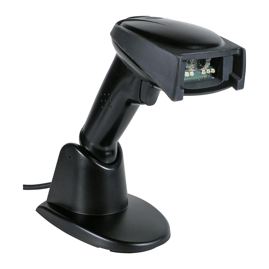
4600rp, 4600g/4600r, 4800i
Commercial/Retail/Industrial Area Imager
User's Guide
™
Table of
Contents
Previous
Page
Next
Page
1
2
3
4
5
Advertisement
Table of Contents
Need help?
Do you have a question about the 4600RSF051CE and is the answer not in the manual?
Ask a question
Questions and answers
Related Manuals for Honeywell 4600RSF051CE
Barcode Reader Honeywell 4600g User Manual
Honeywell commercial/retail/industrial area imager user's guide (244 pages)
Barcode Reader Honeywell 4600g Quick Start Manual
Honeywell scanner quick start guide (21 pages)
Barcode Reader Honeywell 4800i Quick Start Manual
(18 pages)
Barcode Reader Honeywell 4600GSF051C-0F00E Specifications
General purpose 2d imager (2 pages)
Barcode Reader Honeywell 4800ISR051CE Specifications
Industrial 2d imager (2 pages)
Laboratory Equipment Honeywell 4600gHD - Hand Held IMAGETEAM User Manual
Commercial/retail/industrial area imager (248 pages)
Laboratory Equipment Honeywell 4600GHD051CE User Manual
Commercial/retail/industrial area imager (248 pages)
Laboratory Equipment Honeywell 4600GSF051C User Manual
Commercial/retail/industrial area imager (248 pages)
Laboratory Equipment Honeywell Enraf Calibron Small Volume Prover 05 Operation & Installation Manual
(72 pages)
Laboratory Equipment Honeywell 3200 User Manual
Linear imager (100 pages)
Laboratory Equipment Honeywell 3800gPDF - Hand Held Decoding Linear Imager User Manual
General purpose handheld linear imager (156 pages)
Laboratory Equipment Honeywell Genesis XP 7680g User Manual
Presentation area imager (258 pages)
Laboratory Equipment Honeywell Solaris 7980g Quick Start Manual
Presentation area imager (18 pages)
Laboratory Equipment Honeywell Genesis XP 7680GSR Quick Start Manual
Presentation area imager (15 pages)
Laboratory Equipment Honeywell CM Series Quick Start Manual
2d imager module (17 pages)
This manual is also suitable for:
4600ghd - hand held imageteam
4600ghd051c-0f00e
4600ghd051ce
4600gsf051c
4600gsr151cen - hand held imageteam 4600gsr
4600rpsr151c-0g00e - hand held imageteam 4600rpsr
...
Show all
4600rsf051c
4800psf151c-0f00e - hand held imageteam 4800psf
4600rp
4600g
4600r
4800i
Table of Contents
Save PDF
Print
Rename the bookmark
Delete bookmark?
Delete from my manuals?
Login
Sign In
OR
Sign in with Facebook
Sign in with Google
Upload manual
Upload from disk
Upload from URL


Need help?
Do you have a question about the 4600RSF051CE and is the answer not in the manual?
Questions and answers