Honeywell 3800gPDF - Hand Held Decoding Linear Imager User Manual
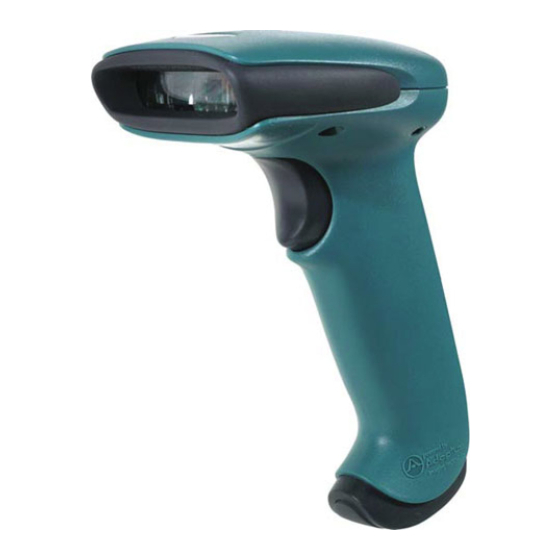
General purpose handheld linear imager
Hide thumbs
Also See for 3800gPDF - Hand Held Decoding Linear Imager:
- Specifications (2 pages) ,
- User manual (156 pages) ,
- Quick start manual (64 pages)
Table of Contents
Advertisement
Advertisement
Table of Contents

Subscribe to Our Youtube Channel
Related Manuals for Honeywell 3800gPDF - Hand Held Decoding Linear Imager


Summary of Contents for Honeywell 3800gPDF - Hand Held Decoding Linear Imager
- Page 1 3800g/3800gHD/3800gPDF General Purpose Handheld Linear Imager User’s Guide ™...
- Page 2 Honeywell International Inc. (“HII”) reserves the right to make changes in speci- fications and other information contained in this document without prior notice, and the reader should in all cases consult HII to determine whether any such changes have been made. The information in this publication does not repre- sent a commitment on the part of HII.
-
Page 3: Table Of Contents
Connecting the Imager When Powered by Host (Keyboard Wedge) ............1-4 Keyboard Wedge Connection ........1-5 Laptop Direct Connect ...........1-6 Connecting the Imager with RS-232 Serial Port ..1-6 IBM 4683 Ports 5B, 9B, and 17 Interface....1-7 Reading Techniques ............1-8 Reading PDF417 Bar Codes........1-8 Resetting the Standard Product Defaults.....1-9... - Page 4 Chapter 4 - Data Editing Prefix/Suffix Overview..........4-1 To Add a Prefix or Suffix........4-1 To Clear One or All Prefixes or Suffixes ....4-2 To Add a Carriage Return Suffix to All Symbologies ............4-3 Prefix Selections ............ 4-3 Suffix Selections ............
- Page 5 Intercharacter, Interfunction, and Intermessage Delays ................4-4 Intercharacter Delay..........4-5 User Specified Intercharacter Delay ......4-5 Interfunction Delay ..........4-6 Intermessage Delay ..........4-6 Chapter 5 - Data Formatting Data Format Editor Introduction ........5-1 To Add a Data Format..........5-1 Other Programming Selections ......5-2 Data Format Editor Commands ......5-2 Data Format Editor..........5-4...
- Page 6 Code 93 ..............7-10 Code 93 Message Length........7-10 Code 93 Code Page ..........7-10 Straight 2 of 5 Industrial (three-bar start/stop) ... 7-11 Straight 2 of 5 Industrial Message Length ... 7-11 Straight 2 of 5 IATA (two-bar start/stop) ....7-11 Straight 2 of 5 IATA Message Length....
- Page 7 UPC E ................7-19 UPC E0 and UPC E1 ...........7-19 UPC E0 and UPC E1 Expand ......7-20 UPC E0 and UPC E1 Addenda Required ....7-20 UPC E0 and UPC E1 Addenda Separator ...7-20 UPC E0 Check Digit..........7-20 UPC E0 Number System ........7-21 UPC E0 Addenda..........7-21...
- Page 8 Keyboard Function Relationships ........ 8-1 Supported Interface Keys ........... 8-3 Chapter 9 - Utilities To Add a Test Code I.D. Prefix to All Symbologies ..9-1 Show Software Revision..........9-1 Show Data Format............9-1 Resetting the Standard Product Defaults ....9-1 Temporary Visual Xpress Configuration ......
- Page 9 Online Technical Assistance ........14-1 Product Service and Repair ........14-2 Online Product Service and Repair Assistance ...14-2 Limited Warranty ............14-3 Appendix A Symbology Chart ............A-1 ASCII Conversion Chart (Code Page 1252) ....A-3 Code Page Mapping of Printed Bar Codes ....A-5...
- Page 10 viii...
- Page 11 This equipment has been tested and found to comply with the limits for a Class B digital device pursuant to part 15 of the FCC Rules. These limits are designed to provide reasonable protection against harmful interference in a residential installation.
- Page 12 Conformité à la règlementation canadienne Cet appareil numérique de la Classe B est conforme à la norme NMB-003 du Canada. Son fonctionnement est assujetti aux conditions suivantes : 1. Cet appareil ne doit pas causer de brouillage préjudiciable.
- Page 13 Those systems will reuse or recycle most of the materials of the product you are disposing in a sound way.
- Page 14 International Eye Safety Statement (LED) This device has been tested in accordance with IEC60825-1:1993 +A:1997 +A2:2001 LED safety, and has been certified to be under the limits of a Class 1 LED device. Caution: Use of controls or adjustments or performance of procedures other than those specified herein may result in hazardous radiation exposure.
- Page 15 3800g Imager Identification Light Source Item Number, Serial Number Compliance Revision Label location...
-
Page 17: Chapter 1 - Getting Started
3800g Models Note: The Honeywell 3800g imager may be used with many interfaces, which are described in this User’s Guide. Refer to the chart below to determine the models that can be used with your interface. Refer to Chapter 6 programming information regarding Secondary Interfaces. -
Page 18: Connecting The Imager With Usb
If you programmed the imager for a different terminal interface and you want to change to a USB Keyboard (PC) or USB Keyboard (Mac), scan one of the fol- lowing codes to program the 3800g. Scanning these codes adds a CR and selects the terminal ID (USB PC Keyboard - 124, USB Macintosh Keyboard - 125). -
Page 19: Ibm Surepos
USB Com Port Emulation Scan the following code to program the 3800g to emulate a regular RS-232- based Com Port. If you are using a Microsoft® Windows® PC, you will need to download a driver from the Honeywell website (www.honeywell.com/aidc . -
Page 20: Plug And Play
Plug and Play bar codes provide instant imager set up for commonly used inter- faces. Note: After you scan one of the codes, power cycle the host terminal to have the interface in effect. Connecting the Imager When Powered by Host (Keyboard Wedge) An imager can be connected between the keyboard and PC as a “keyboard... -
Page 21: Keyboard Wedge Connection
3. Connect the appropriate interface cable to the imager and to the terminal/ computer. 4. Turn the terminal/computer power back on. Note: You will not hear a power-up beep because the 3800g is factory defaulted to a USB connection. You must scan the IBM PC AT and Compatibles... -
Page 22: Laptop Direct Connect
1. Turn off power to the terminal/computer. 2. Connect the appropriate interface cable to the imager. Note: For the imager to work properly, you must have the correct cable for your type of terminal/computer. 3. Plug the serial connector into the serial port on your computer. Tighten the two screws to secure the connector to the port. -
Page 23: Ibm 4683 Ports 5B, 9B, And 17 Interface
RS-232 protocol. Scanning the RS-232 interface bar code, programs the imager for an RS-232 interface at 38,400 baud, parity–none, 8 data bits, 1 stop bit, and adds a suffix of a CR LF. RS-232 Interface... -
Page 24: Reading Techniques
The best focus point for reading most code densities is about 5 inches (12.7 cm) from the unit. To read a single bar code or multiple bar codes (on a page or on an object), hold the imager at an appropriate distance from the target, pull the trigger, and center the aiming beam on the bar code. -
Page 25: Resetting The Standard Product Defaults
Resetting the Standard Product Defaults If you aren’t sure what programming options are in your imager, or you’ve changed some options and want the factory settings restored, scan the Stan- dard Product Default Settings bar code below. Standard Product Default Settings... - Page 26 1 - 10...
-
Page 27: Chapter 2 - Terminal Interfaces
ID. Scan Save to save your selection. For example, an IBM AT terminal has a Terminal ID of 003. You would scan the Terminal ID bar code, then 0, 0, 3 from the... -
Page 28: Supported Terminals
Esprit 200, 400 Heath Zenith PC, AT Vectra PS/2 25, 30, 77DX2 AT, PS/2 30–286, 50, 55SX, 60, 70, 70–061, 70–121, 80 IBM 102 key 3151, 3161, 3162, 3163, 3191, 3192, 3194, 3196, 3197, 3471, 3472, 3476, 3477 IBM 122 key... - Page 29 Supported Terminals (Continued) Terminal Model(s) Terminal ID Telex 122 key 078, 078A, 79, 80, 191, 196, 1191,1192, 1471, 1472, 1476, 1477, 1482, 1483 USB PC Keyboard 124 * USB Mac Keyboard USB Com Port USB HIDPOS * Factory default setting...
-
Page 30: Keyboard Country
As a general rule, the following characters are supported, but need special care for countries other than the United States: @ | $ # { } [ ] = / ‘ \ < > ~ * United States Belgium... -
Page 31: Keyboard Style
Automatic Caps Lock is used if you change the Caps Lock key on and off. The software tracks and reflects if you have Caps Lock on or off (AT and PS/2 only). This selection can only be used with systems that have an LED which notes the Caps Lock status. -
Page 32: Keyboard Modifiers
Control + ASCII Mode On: The imager sends key combinations for ASCII control characters for values 00-1F. Windows is the preferred mode. All key- board country codes are supported. DOS mode is a legacy mode, and it does not support all keyboard country codes. New users should use the Windows mode. - Page 33 Default = Off Numeric Keypad Mode On * Numeric Keypad Mode Off Automatic Direct Connect Mode: This selection can be used if you have an IBM AT style terminal and the system is dropping characters. Default = Off Automatic Direct...
-
Page 34: Rs-232 Baud Rate
RS-232 Word Length: Data Bits, Stop Bits, and Parity Data Bits sets the word length at 7 or 8 bits of data per character. If an applica- tion requires only ASCII Hex characters 0 through 7F decimal (text, digits, and punctuation), select 7 data bits. - Page 35 Parity provides a means of checking character bit patterns for validity. Default = None. 7 Data, 1 Stop, Parity Even 7 Data, 1 Stop, Parity None 7 Data, 1 Stop, Parity Odd 7 Data, 2 Stop, Parity Even 7 Data, 2 Stop Parity None...
-
Page 36: Rs-232 Handshaking
RS-232 Handshaking RS-232 handshaking is a set of rules concerning the exchange of data between serially communicating devices. Default = RTS/CTS, XON/XOFF and ACK/ NAK Off . RTS/CTS On * RTS/CTS Off XON/XOFF On * XON/OFF Off ACK/NAK On * ACK/NAK Off... -
Page 37: Chapter 3 - Output
Good Read Indicators Beeper – Good Read The beeper may be programmed On or Off in response to a good read. Turning this option off, only turns off the beeper response to a good read indication. All error and menu beeps are still audible. Default = On. -
Page 38: Beeper Duration - Good Read
* On Number of Beeps – Good Read The number of beeps of a good read can be programmed from 1 - 9. The same number of beeps will be applied to the beeper and LED in response to a good read. -
Page 39: Good Read Delay
Long Delay (1500 ms) User-Specified Good Read Delay If you want to set your own length for the good read delay, scan the bar code below, then set the delay (from 0-30,000 milliseconds) by scanning digits from the inside back cover, then scanning Save . -
Page 40: Automatic Trigger
Presentation Mode uses ambient light to detect bar codes. The LEDs are off for ambient conditions until a change occurs in the imager’s field of view. Then the LEDS turn on automatically to read the code. If the light level in the room is not high enough, Presentation Mode may not work properly. -
Page 41: Reread Delay
When centering is turned on, the imager only reads codes that intersect or are contained within the centering window you set up. At least part of a bar code must be within the window to be decoded or out- put by the imager. - Page 42 To change the left or right edge of the centering window, scan Centering On, then scan one of the following bar codes. Then scan the percent you want to shift the centering window using digits on the inside back cover of this manual.
- Page 43 Example: If you have two bar codes next to one another and the centering window is set to 40% left edge and 60% right edge, only the bar code that intersects that window will be decoded. Decoded bar code 100%...
-
Page 44: Output Sequence Overview
Output Sequence Overview Require Output Sequence When turned off, the bar code data will be output to the host as the imager decodes it. When turned on, all output data must conform to an edited sequence or the imager will not transmit the output data to the host device. -
Page 45: Output Sequence Editor
When the output sequence is Off , the bar code data is output to the host as the imager decodes it. - Page 46 Output Sequence Example In this example, you are scanning Code 93, Code 128, and Code 39 barcodes, but you want the image scanner to output Code 39 1st, Code 128 2nd, and Code 93 3rd, as shown below. Note: Code 93 must be enabled to use this example.
- Page 47 To program the previous example using specific lengths, you would have to count any programmed prefixes, suffixes, or formatted characters as part of the length. If you use the example on page 3-10, but assume a <CR> suffix and specific code lengths, you would use the following command line:...
-
Page 48: Multiple Symbols
* Off No Read With No Read turned On , the imager sends an “NR” to the host if you pull and release the trigger without reading a code (e.g., bad bar code). If No Read is turned Off , the “NR” will not be sent to the host. -
Page 49: Video Reverse
Video Reverse Video Reverse is used to allow the imager to read bar codes that are inverted. The “Off” bar code below is an example of this type of bar code. Note: If additional menuing is required, Video Reverse must be disabled to read the menu bar codes and then re-enabled after menuing is completed. - Page 50 3 - 14...
-
Page 51: Chapter 4 - Data Editing
A-3, plus Code I.D. and AIM I.D. • You can string together several entries for several symbologies at one time. • Enter prefixes and suffixes in the order in which you want them to appear on the output. -
Page 52: To Clear One Or All Prefixes Or Suffixes
To add AIM I.D., scan 5, C, 8, 1. To add a backslash (\), scan 5, C, 5, C. Note: To add a backslash (\) as in Step 7, you must scan 5C twice – once to create the leading backslash and then to create the backslash itself. -
Page 53: To Add A Carriage Return Suffix To All Symbologies
Your change is automatically saved. To Add a Carriage Return Suffix to All Symbologies Scan the following bar code if you wish to add a carriage return suffix to all sym- bologies at once. This action first clears all current suffixes, then programs a carriage return suffix for all symbologies. -
Page 54: Suffix Selections
Intercharacter, interfunction, and intermessage delays slow the transmission of data, increasing data integrity. Each delay is composed of a 5 millisecond step. You can program up to 99 steps (of 5 ms each) for a range of 0-495 ms. 4 - 4... -
Page 55: Intercharacter Delay
Page 1252) on page A-3. Delay Length Character to Trigger Delay To remove this delay, scan the Delay Length bar code, and set the number of steps to 0. Scan the Save bar code using the Programming Chart inside the back cover of this manual. -
Page 56: Interfunction Delay
An interfunction delay of up to 495 milliseconds may be placed between the transmission of each segment of the message string. Scan the Interfunction Delay bar code below, then scan the number of milliseconds and the Save bar code using the Programming Chart inside the back cover of this manual. -
Page 57: Chapter 5 - Data Formatting
You may use the Data Format Editor to change the imager’s output. For exam- ple, you can use the Data Format Editor to insert characters at certain points in bar code data as it is scanned. The selections in the following pages are used only if you wish to alter the output. -
Page 58: Other Programming Selections
Programming Chart inside the back cover of this manual. If you are clearing an alternate format, scan 1, 2, or 3, depending on the alternate format you are clearing. Scan the Terminal Type (refer to the Supported Terminals Chart on page 2-2), Code I.D. - Page 59 When the FC command is encountered, the suppress function is termi- nated. The cursor is not moved by the FB command. Syntax = FBnnxxyy . .zz where nn is a count of the number of suppressed characters in the list 5 - 3...
-
Page 60: Data Format Editor
.. zz is the list of characters to be suppressed. (xx stands for the hex value for an ASCII code, see ASCII Conversion Chart (Code Page 1252) on page A-3.) FC Disables suppress filter and clear all suppressed characters. Syntax = FC. -
Page 61: Data Formatter
Data Formatter When Data Formatter is turned off, the bar code data is output to the host as read (including prefixes and suffixes). Choose one of the following options. Default = Data Formatter On. * Data Formatter On, but Not Required... - Page 62 5 - 6...
-
Page 63: Chapter 6 - Secondary Interface
The secondary interface can be programmed at any time. You can temporarily disable the secondary interface, but still retain the second- ary interface settings in the imager’s memory by scanning the Disable bar code below. To re-enable the secondary interface, scan the Enable bar code. -
Page 64: Secondary Trigger Mode
RS-232 programmable selections are used by both the primary and secondary interfaces. Changing an RS-232 parameter (e.g., baud rate or parity), while in primary or secondary mode will affect both interfaces. If you want to change the RS-232 settings, refer to the Connecting the Imager with RS-232 Serial Port section on page 1-6. - Page 65 Scan the Hands Free Time-Out bar code, then scan the time-out duration (from 0-300,000 milliseconds) from the inside back cover, and Save . Default = 5,000 ms. Hands Free Time-Out 6 - 3...
- Page 66 6 - 4...
-
Page 67: Introduction
Symbologies Introduction This programming section contains the following menu selections. Refer to Chapter 11 for settings and defaults. • All Symbologies • Korea Post Code • Label Code • China Post Code (3800gHD/ 3800gPDF only) • Codabar • Matrix 2 of 5 •... -
Page 68: All Symbologies
All Symbologies Off Message Length You are able to set the valid reading length of some of the bar code symbologies. If the data length of the scanned bar code doesn’t match the valid reading length, the imager will issue an error beep. You may wish to set the same value for minimum and maximum length to force the imager to read fixed length bar code data. -
Page 69: Codabar
Codabar Check Character Codabar check characters are created using different “modulos.” You can pro- gram the imager to read only Codabar bar codes with Modulo 16 check charac- ters. Default = No Check Character. No Check Character indicates that the imager reads and transmits bar code data with or without a check character. -
Page 70: Codabar Concatenation
When Check Character is set to Validate, but Don’t Transmit , the unit will only read Codabar bar codes printed with a check character, but will not transmit the check character with the scanned data. * No Check Character Validate Modulo 16, but Don’t Transmit... -
Page 71: Codabar Message Length
When Check Character is set to Validate, but Don’t Transmit, the unit only reads Code 39 bar codes printed with a check character, but will not transmit the check character with the scanned data. -
Page 72: Code 39 Message Length
(excluding the start and stop symbols), and does not immediately trans- mit the data. The imager stores the data in the order in which the bar codes are read, deleting the first space from each. The imager transmits the appended data when it reads a Code 39 bar code that starts with a character other than a space. -
Page 73: Code 32 Pharmaceutical (Paraf)
Code 32 Pharmaceutical (PARAF) Code 32 Pharmaceutical is a form of the Code 39 symbology used by Italian pharmacies. This symbology is also known as PARAF. Default = Off. Note: Trioptic Code must be turned off to scan Code 32 Pharmaceutical codes. -
Page 74: Code 39 Code Page
If this is the case, scan the bar code below, select the code page with which the bar codes were created from the chart,... -
Page 75: Interleaved 2 Of 5 Message Length
When Check Digit is set to Validate and Transmit, the imager only reads Inter- leaved 2 of 5 bar codes printed with a check digit, and will transmit this digit at the end of the scanned data. Default = No Check Digit. -
Page 76: Code 93
If this is the case, scan the bar code below, select the code page with which the bar codes were created from the chart,... -
Page 77: Straight 2 Of 5 Industrial (Three-Bar Start/Stop)
<Default All Straight 2 of 5 Settings> Straight 2 of 5 Industrial * Off Straight 2 of 5 Industrial Message Length Scan the bar codes below to change the message length. Refer to Message Length on page 7-2 for additional information. Minimum and Maximum lengths = 1-48. -
Page 78: Straight 2 Of 5 Iata Message Length
Straight 2 of 5 IATA Message Length Scan the bar codes below to change the message length. Refer to Message Length on page 7-2 for additional information. Minimum and Maximum lengths = 1-48. Minimum Default = 4, Maximum Default = 48. -
Page 79: Code 11
<Default All Code 11 Settings> Code 11 * Off Check Digits Required This option sets whether 1 or 2 check digits are required with Code 11 bar codes. Default = Two Check Digits. One Check Digit * Two Check Digits... -
Page 80: Code 11 Message Length
ISBT formats requires a paid license. The ISBT 128 Application Specification describes 1) the critical data elements for labeling blood products, 2) the current recommendation to use Code 128 due to its high degree of security and its space-efficient design, 3) a variation of Code 128 that supports concatenation of neighboring symbols, and 4) the standard layout for bar codes on a blood product label. -
Page 81: Code 128 Message Length
If this is the case, scan the bar code below, select the code page with which the bar codes were created from the chart,... -
Page 82: Telepen Output
* Off Telepen Output Using AIM Telepen Output, the imager reads symbols with start/stop pattern 1 and decodes them as standard full ASCII (start/stop pattern 1). When Original Telepen Output is selected, the imager reads symbols with start/stop pattern 1 and decodes them as compressed numeric with optional full ASCII (start/stop pattern 2). -
Page 83: Upc A
* On UPC A Number System The numeric system digit of a U.P.C. symbol is normally transmitted at the beginning of the scanned data, but the unit can be programmed so it will not transmit it. Default = On. * On... -
Page 84: Upc A Addenda
UPC A Addenda This selection adds 2 or 5 digits to the end of all scanned UPC A data. Default = Off for both 2 Digit and 5 Digit Addenda. 2 Digit Addenda On * 2 Digit Addenda Off 5 Digit Addenda On... -
Page 85: Upc-A/Ean-13
Most U.P.C. bar codes lead with the 0 number system. For these codes, use the UPC E0 selection. If you need to read codes that lead with the 1 number sys- tem, use the UPC E1 selection. Default = On (UPC E0) and Off (UPC E1). -
Page 86: Upc E0 And Upc E1 Expand
* Not Required UPC E0 and UPC E1 Addenda Separator When this feature is on, there is a space between the data from the bar code and the data from the addenda. When turned off, there is no space. Default = On. -
Page 87: Upc E0 Number System
Default = On. * On UPC E0 Addenda This selection adds 2 or 5 digits to the end of all scanned UPC E data. Default = Off for both 2 Digit and 5 Digit Addenda. 2 Digit Addenda On... -
Page 88: Ean/Jan 13 Check Digit
Default = On. * On EAN/JAN 13 Addenda This selection adds 2 or 5 digits to the end of all scanned EAN/JAN 13 data. Default = Off for both 2 Digit and 5 Digit Addenda. 2 Digit Addenda On... -
Page 89: Ean/Jan 13 Addenda Separator
EAN/JAN 13 Addenda Separator When this feature is on, there is a space between the data from the bar code and the data from the addenda. When turned off, there is no space. Default = On. * On Note: If you want to enable or disable EAN13 with Extended Coupon Code,... -
Page 90: Ean/Jan 8 Check Digit
Default = On. * On EAN/JAN 8 Addenda This selection adds 2 or 5 digits to the end of all scanned EAN/JAN 8 data. Default = Off for both 2 Digit and 5 Digit Addenda. 2 Digit Addenda On... -
Page 91: Ean/Jan 8 Addenda Separator
EAN/JAN 8 Addenda Separator When this feature is on, there is a space between the data from the bar code and the data from the addenda. When turned off, there is no space. Default = On. * On <Default All MSI Settings>... -
Page 92: Msi Message Length
MSI Message Length Scan the bar codes below to change the message length. Refer to Message Length on page 7-2 for additional information. Minimum and Maximum lengths = 4-48. Minimum Default = 4, Maximum Default = 48. Minimum Message Length... -
Page 93: Gs1 Databar Limited
GS1 DataBar Omnidirectional * On GS1 DataBar Limited < Default All GS1 DataBar Limited Settings > GS1 DataBar Limited * On GS1 DataBar Expanded < Default All GS1 DataBar Expanded Settings > 7 - 27... -
Page 94: Gs1 Databar Expanded Message Length
GS1 DataBar Expanded * On GS1 DataBar Expanded Message Length Scan the bar codes below to change the message length. Refer to Message Length on page 7-2 for additional information. Minimum and Maximum lengths = 4-74. Minimum Default = 4, Maximum Default = 74. -
Page 95: Korea Post Code
<Default All Korea Post Code Settings> Korea Post Code * Off Korea Post Message Length Scan the bar codes below to change the message length. Refer to Message Length on page 7-2 for additional information. Minimum and Maximum lengths = 2-80. Minimum Default = 4, Maximum Default = 48. -
Page 96: Posicode Message Length
PosiCode A and B * On You have to have PosiCode A and B on to read any of the PosiCode symbolo- gies. A and B On (No Limited) A and B and Limited A On (Limited B Off) * A and B and Limited B On... -
Page 97: Codablock F
<Default All Codablock F Settings> Codablock F * Off Codablock F Message Length Scan the bar codes below to change the message length. Refer to Message Length on page 7-2 for additional information. Minimum and Maximum lengths = 1-2048. Minimum Default = 1, Maximum Default = 2048. -
Page 98: Code 16K Message Length
Code 16K * Off Code 16K Message Length Scan the bar codes below to change the message length. Refer to Message Length on page 7-2 for additional information. Minimum and Maximum lengths = 0-160. Minimum Default = 1, Maximum Default = 160. -
Page 99: Code 49 Message Length
Code 49 * On Code 49 Message Length Scan the bar codes below to change the message length. Refer to Message Length on page 7-2 for additional information. Minimum and Maximum lengths = 1-81. Minimum Default = 1, Maximum Default = 81. -
Page 100: Micropdf417 (3800Ghd/3800Gpdf Only)
Maximum Message Length GS1 Composite Codes Linear codes are combined with a unique 2D composite component to form a new class called GS1 Composite symbology. GS1 Composite symbologies allow for the co-existence of symbologies already in use. Default = Off. -
Page 101: Upc/Ean Version
UPC/EAN Version Scan the UPC/EAN Version On barcode to decode GS1 Composite symbols that have a UPC or EAN linear component. (This does not affect GS1 Compos- ite symbols with a GS1-128 or GS1linear component. If either of these codes are the linear component, either Code 128 or the correct GS1 code must be enabled.) Default = Off. -
Page 102: Label Code (3800Ghd/3800Gpdf Only)
TCIF Linked Code 39 (TLC39) (3800gHD/ 3800gPDF only) This code is a composite code since it has a Code 39 linear component and a MicroPDF417 stacked code component. All barcode readers are capable of reading the Code 39 linear component. The MicroPDF417 component can only be decoded if TLC39 On is selected. -
Page 103: Chapter 8 - Interface Keys
Interface Keys Keyboard Function Relationships The following Keyboard Function Code, Hex/ASCII Value, and Full ASCII “CTRL”+ relationships apply to all terminals that can be used with the imager. Refer to page 2-6 enable Control + ASCII mode. Function Code HEX/ASCII Value Full ASCII “CTRL”... - Page 104 The last five characters in the Full ASCII “CTRL”+ column ( [ \ ] 6 - ), apply to US only. The following chart indicates the equivalents of these five characters for different countries. Country Codes United States Belgium <...
-
Page 105: Supported Interface Keys
Field Exit/New Line Insert Insert Insert Escape Escape Reserved Error Reset Home Home Home Print Print Back Space Back Space Back Space Back Tab Back Tab Backfield/Back Tab Reserved * IBM 3191/92, 3471/72, 3196/97, 3476/77, Telex (all models) 8 - 3... - Page 106 Error Reset Home Reserved Print Print Back Space Back Space Back Tab Back Field Reserved Home * IBM 3196/97, 3476/77, 3191/92, 3471/72, Memorex Telex (all models) with 102 key keyboards ** Memorex Telex with 88 key keyboards 8 - 4...
- Page 107 Supported Interface Keys Esprit 200, 400 Esprit 200, 400 Esprit 200, 400 ANSI ASCII ASCII Supported Keys Supported Keys Supported Keys Reserved Reserved Reserved New Line New Line New Line New Line New Line New Line Delete New Line New Line...
- Page 108 Supported Interface Keys Apple Mac/iMac ASCII Supported Keys Reserved Enter/Numpad Enter CAPS ALT make ALT break CNTRL make CNTRL break RETURN APPLE make APPLE break RETURN Ins Help Home Prnt Scrn BACKSPACE LSHIFT TAB BACKSPACE 8 - 6...
-
Page 109: Chapter 9 - Utilities
Utilities To Add a Test Code I.D. Prefix to All Symbologies This selection allows you to turn on transmission of a Code I.D. before the decoded symbology. (See the Symbology Chart, included in the "Appendix A" on page A-1) for the single character code that identifies each symbology.) This action first clears all current prefixes, then programs a Code I.D. -
Page 110: Temporary Visual Xpress Configuration
Visual Xpress on page 10-1 for additional information about Visual Xpress. Note: If you have a unit capable of keyboard wedge mode, scan the bar code below and the unit will communicate in RS-232 mode, allowing it to work with Visual Xpress. To convert the imager back to keyboard wedge communication, cycle the power. -
Page 111: Chapter 10 - Visual Xpress
The Visual Xpress software performs the following operations: Scan Data Scan Data allows you to scan bar codes and display the bar code data in a win- dow. Scan Data lets you send serial commands to the imager and receive imager response that can be seen in the Scan Data window. -
Page 112: Installing Visual Xpress From The Web
6. Once you have finished downloading the file, exit the web site. 7. Using Explorer, go to the c:\windows\temp file and unzip the file you saved. 8. Double click on Setup.exe and follow the screen prompts to install the Visual Xpress program. -
Page 113: Chapter 11 - Serial Programming Commands
PC com port using terminal emulation software. Conventions The following conventions are used for menu and query command descriptions: parameter A label representing the actual value you should send as part of a command. [ option ] An optional part of a command. -
Page 114: Query Commands
Tag Field Usage When a query is used in place of a Tag field, the query applies to the entire set of commands available for the particular storage table indicated by the Storage field of the command. In this case, the SubTag and Data fields should not be used because they are ignored by the device. -
Page 115: Examples Of Query Commands
Examples of Query Commands In the following examples, a bracketed notation [ ] depicts a non-displayable response. Example: Example #1:What is the range of possible values for Codabar Coding Enable? Enter: cbrena*. Response: CBRENA0-1[ACK] This response indicates that Codabar Coding Enable (CBRENA) has a range of values from 0 to 1 (off and on). -
Page 116: Trigger Commands
Product Default Settings bar code below. Standard Product Default Settings The chart on the following pages lists the factory default settings for each of the menu commands (indicated by an asterisk (*) on the programming pages). 11 - 4... -
Page 117: Menu Commands
Menu Commands Serial Setting Command Selection Page * Indicates default # Indicates a numeric entry Factory Default Set- Default DEFALT tings Terminal Interfaces Terminal ID USB PC Keyboard TERMID### Program Keyboard *USA KBDCTY0 Country Belgium KBDCTY1 Denmark KBDCTY8 Finland KBDCTY2... - Page 118 Serial Setting Command Selection Page * Indicates default # Indicates a numeric entry Keyboard Modifiers Windows Mode Control + KBDCAS2 ASCII *Control + ASCII Off KBDCAS0 DOS Mode Control + KBDCAS1 ASCII Mode On *Turbo Mode Off KBDTMD0 Turbo Mode On...
-
Page 119: Output Selections
Serial Setting Command Selection Page * Indicates default # Indicates a numeric entry Word Length: Data 7 Data, 1 Stop, Parity 232WRD3 Bits, Stop Bits, and Even Parity 7 Data, 1 Stop, Parity 232WRD0 None 7 Data, 1 Stop, Parity... - Page 120 *No Delay DLYGRD0 Short Delay (500 ms) DLYGRD50 Medium Delay (1000 ms) DLYGRD10 Long Delay (1500 ms) DLYGRD15 User-Specified Good Range 0 - 30,000 ms DLYGRD#### Read Delay Trigger Mode *Manual/Serial Trigger TRGMOD0 Read Time-Out (0 - TRG- 300,000 ms) *30,000...
- Page 121 3-13 SHOTGN0 No Read 3-12 SHWNRD1 *Off 3-12 SHWNRD0 Video Reverse 3-12 VIDREV1 *Off 3-12 VIDREV0 Prefix/Suffix Selections Add CR Suffix to All Symbologies VSUFCR Prefix Add Prefix PREBK2## Clear One Prefix PRECL2 Clear All Prefixes PRECA2 11 - 9...
- Page 122 DLYFNC## Intermessage Delay DLYMSG## Data Formatter Selections Data Format Editor *Default Data Format DFMDF3 (None) Enter Data Format DFMBK3## Clear One Data Format DFMCL3 Clear All Data Formats DFMCA3 Data Formatter DFM_EN0 *On, but Not Required DFM_EN1 On, Required DFM_EN2...
- Page 123 CBRCK21 Validate, and Transmit CBRCK22 Codabar Concatena- *Off CBRCCT0 tion CBRCCT1 Require CBRCCT2 Codabar Message Minimum (2 - 60) *4 CBRMIN## Length Maximum (2 - 60) *60 CBRMAX## Code 39 Default All Code 39 C39DFT Settings Code 39 C39ENA0 C39ENA1 Code 39 Start/Stop *Don’t Transmit...
- Page 124 Code 93 Message Minimum (0 - 80) *0 C93MIN## 7-10 Length Maximum (0 - 80) *80 C93MAX## 7-10 Straight 2 of 5 Indus- Default All Straight 2 of 5 R25DFT 7-11 trial Settings Straight 2 of 5 Indus- *Off R25ENA0 7-11...
- Page 125 Straight 2 of 5 IATA Minimum (1 - 48) *4 A25MIN## 7-12 Message Length Maximum (1 - 48) *48 A25MAX## 7-12 Matrix 2 of 5 Default All Matrix 2 of 5 X25DFT 7-12 Settings Matrix 2 of 5 *Off X25ENA0 7-12 X25ENA1...
- Page 126 7-16 TELENA1 7-16 Telepen Output *AIM Telepen Output TELOLD0 7-16 Original Telepen Output TELOLD1 7-16 Telepen Message Minimum (1 - 60) *1 TELMIN## 7-16 Length Maximum (1 - 60) *60 TELMAX## 7-16 UPC A Default All UPADFT 7-17 UPC A Settings...
- Page 127 Command Selection Page * Indicates default # Indicates a numeric entry UPC E Expand *Off UPEEXP0 7-20 UPEEXP1 7-20 UPC E Check Digit UPECKX0 7-20 UPECKX1 7-20 UPC E Number Sys- UPENSX0 7-21 UPENSX1 7-21 UPC E 2 Digit *Off...
- Page 128 *Validate Type 10, but MSICHK0 7-25 Don’t Transmit Validate Type 10 and MSICHK1 7-25 Transmit MSI Message Length Minimum (4 - 48) *4 MSIMIN## 7-26 Maximum (4 - 48) *48 MSIMAX## 7-26 Plessey Code Default All Plessey Set- PLSDFT 7-26...
- Page 129 RSEDFT 7-28 Expanded Expanded Settings GS1 DataBar RSEENA0 7-28 Expanded RSEENA1 7-28 GS1 DataBar Minimum (4 - 74) *4 RSEMIN## 7-28 Expanded Msg. Maximum (4 - 74) *74 RSEMAX## 7-28 Length China Post Code Default All China Post CPCDFT 7-28...
- Page 130 # Indicates a numeric entry PosiCode POSENA0 7-30 POSENA1 7-30 A and B On POSLIM0 7-30 A and B and Limited A POSLIM1 7-30 *A and B and Limited B POSLIM2 7-30 PosiCode Msg. Length Minimum (2 - 80) *4 POSMIN## 7-30...
- Page 131 Serial Setting Command Selection Page * Indicates default # Indicates a numeric entry PDF417 Default All PDF417 Set- 7-33 (3800gHD/3800gPDF tings PDFDFT only PDF417 7-33 PDFENA1 7-33 PDFENA0 PDF417 Msg. Length Minimum (1-2750) *1 7-34 PDFMIN Maximum (1-2750) 7-34 PDFMAX...
- Page 132 11 - 20...
-
Page 133: Chapter 12 - Product Specifications
4.4 inches (11.2 cm) Width 3.1 inches (7.9 cm) Weight 5.6 ounces (160 g) Light Source 630 nm visible red LED @ 800µW max radiant power Scan Rate 270 scans per second in most usages ±65 degrees Skew Angle ±65 degrees... -
Page 134: 3800Ghd/3800Gpdf Product Specifications
4.4 inches (11.2 cm) Width 3.1 inches (7.9 cm) Weight 5.6 ounces (160 g) Light Source 628 nm visible red LED @ 300µW max radiant power Scan Rate 270 scans per second in most usages ±65 degrees Skew Angle ±65 degrees... - Page 135 Standard Cable Pinouts Keyboard Wedge 12 - 3...
- Page 136 Standard Cable Pinouts Serial Output 12 - 4...
- Page 137 Standard Cable Pinouts 12 - 5...
- Page 138 12 - 6...
-
Page 139: Chapter 13 - Maintenance
(or a mild soapy water solu- tion). If a soapy water solution is used, rinse with a clean lens tissue dampened with water only. -
Page 140: Replacing The Interface Cable
The standard interface cable is attached to the scanner with an 10-pin modular connector. When properly seated, the connector is held in the 3800g scanner’s handle by a flexible retention tab. The interface cable is designed to be field replaceable. - Page 141 (the Enter/Return key or the Tab key, for example). You need to program a suffix. Programming a suffix enables the scanner to out- put the bar code data plus the key you need (such as “CR”) to enter the data into your application. Refer to...
- Page 142 13 - 4...
-
Page 143: Chapter 14 - Customer Support
Customer Support Technical Assistance If you need assistance installing or troubleshooting your device, please call your distributor or the nearest technical support office: North America/Canada Telephone: (800) 782-4263 Fax number: (315) 554-6705 E-mail: natechsupport@honeywell.com Latin America Telephone: (803) 835-8000 Telephone: (800) 782-4263 E-mail: latechsupport@honeywell.com... -
Page 144: Product Service And Repair
Product Service and Repair Honeywell International Inc. provides service for all its products through service centers throughout the world. To obtain warranty or non-warranty service, contact the appropriate location below to obtain a Return Material Authorization number (RMA #) before returning the product. -
Page 145: Limited Warranty
HII factory or authorized service center for inspection. No product will be accepted by HII without a Return Materials Authorization, which may be obtained by contacting HII. In the event that the product is returned to HII or its authorized service center within the Warranty Period and HII determines to its... - Page 146 Use of any peripherals not provided by the manufacturer may result in damage not covered by this warranty. This includes but is not limited to: cables, power supplies, cradles, and docking stations. HII extends these warranties only to the first end-users of the products.
-
Page 147: Symbology Chart
(0x6A) Code 16K 0, 1, 2, 4 o (0x6F) Code 32 Pharmaceutical (PARAF) < (0x3C) Code 39 (supports Full ASCII mode) 0, 1, 3, 4, 5, 7 b (0x62) Code 49 0, 1, 2, 4 l (0x6C) 0-9, A-Z,... - Page 148 E (0x45) UPC-E1 (obsolete) E (0x45) Note: “m” represents the AIM modifier character. Refer to International Technical Specification, Symbology Identifiers, for AIM modifier character details. Prefix/Suffix entries for specific symbologies override the universal (All Symbologies, 99) entry. A - 2...
-
Page 149: Ascii Conversion Chart (Code Page 1252
ASCII Conversion Chart (Code Page 1252 Note: This table applies to U.S. style keyboards. Certain characters may differ depending on your Country Code/PC regional settings. Dec Hex Char Hex Char Dec Char Dec Hex Char ‘ “ & ‘ <... - Page 150 ¶ Ö ö — · × ÷ ˜ ¸ Ø ø ™ ¹ Ù ù š Ú ú › » Û û œ ¼ Ü ü ½ Ý ý ž ¾ Þ þ Ÿ ¿ ß ÿ A - 4...
-
Page 151: Code Page Mapping Of Printed Bar Codes
If this is the case, select the code page with which the bar codes were created. The data characters should then appear properly. - Page 152 A - 6...
- Page 153 Sample Symbols UPC A 0 123456 7890 Interleaved 2 of 5 1234567890 Code 128 Code 128 EAN 13 9 780330 290951 EAN 8 3210 5 UPC-E 456123 3800g/3800gHD/3800gPDF User’s Guide...
- Page 154 Sample Symbols Code 39 Codabar BC321 Code 93 A13579B Straight 2 of 5 Industrial 123456-9$ 123456 Matrix 2 of 5 6543210 GS1 DataBar (01)00123456789012 PDF417 Car Registration Micro PDF417 Test Message 3800g/3800gHD/3800gPDF User’s Guide...
-
Page 155: Programming Chart
Programming Chart Discard Save Note: If you make an error while scanning the letters or digits (before scanning Save), scan Discard, scan the correct letters or digits, and Save. - Page 156 Honeywell 700 Visions Drive P.O. Box 208 Skaneateles Falls, NY 13153-0208 3800g-UG Rev C 4/09...
Need help?
Do you have a question about the 3800gPDF - Hand Held Decoding Linear Imager and is the answer not in the manual?
Questions and answers