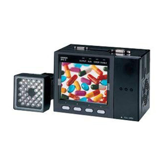
Omron ZFX-C User Manual
Vision sensor with built-in lcd monitor
Hide thumbs
Also See for ZFX-C:
- Brochure & specs (15 pages) ,
- User manual (22 pages) ,
- Command reference manual (66 pages)

Related Manuals for Omron ZFX-C


Summary of Contents for Omron ZFX-C
-
Page 1: Users Manual
Cat. No. Z264-E1-06A Smart Sensor ZFX-C Vision Sensor with built-in LCD monitor USERS MANUAL... - Page 3 • To ensure correct use, please read this manual thoroughly to deepen your understanding of the product. • Please keep this manual in a safe place so that it can be referred to whenever necessary. Manuals Provided with this Product...
-
Page 4: Before Use
APPLICATION CONSIDERATIONS (Please Read) BEFORE USE User's Manual BASIC OPERATIONS SETTING THE MEASUREMENT CONDITIONS FUNCTIONS USED DURING OPERA- TION ADDITIONAL FUNCTIONS PARALLEL INTERFACE APPENDICES Smart Sensor Vision Sensor with built-in LCD monitor ZFX-C... - Page 5 The following are some examples of applications for which particular attention must be given. This is not intended to be an exhaustive list of all possible uses of the products, nor is it intended to imply that the uses listed may be suitable for the products: •...
-
Page 6: Performance Data
THE INTENDED USE WITHIN THE OVERALL EQUIPMENT OR SYSTEM. PERFORMANCE DATA Performance data given in this document is provided as a guide for the user in determining suitability and does not constitute a warranty. It may represent the result of OMRON’s test conditions, and the users must correlate it to actual application requirements. - Page 7 The camera with lighting emits visible light, which may adversely affect the eyes in rare instances. Do not look directly into the light emitted from the Camera. When the subject is a specular reflective object, protect your eyes from reflected light.
- Page 8 1.Installation Environment • Do not use the product in environments where it can be exposed to inflammable/explosive gas. • To secure the safety of operation and maintenance, do not install the product close to high-voltage devices and power devices. • Install the product in such a way that its ventilation holes are not blocked.
-
Page 9: Ventilation Film
• Use only combinations of the Camera, Controller and Strobe Controller specified in this manual. Using other combinations may cause malfunction or damage. • Do not turn the power OFF in the following instances. Doing so will damage data that is in the process of being saved. - Page 10 5.Optional Lighting Connector When the optional lighting is not connected, be sure to attach the connector cap. Otherwise, its protective structure might be impaired. 6.Camera's Connector Cap When using only one camera, attach the connector cap to cameras that are not in use.
- Page 11 Editor's Note ■ Meaning of Symbols Menu items that are displayed on the Controller's LCD screen, and windows, dialog boxes and other GUI elements displayed on the PC are indicated enclosed by brackets "[ ]". ■ Visual Aids Indicates points that are important to achieve the full product performance, Important such as operational precautions.
-
Page 12: Table Of Contents
Starting Measurement - RUN Mode........42... -
Page 13: Setting The Measurement Conditions
Setting Measurement Items ........46... - Page 14 Operation Settings ..........145 Measurement Control Conditions ........147 Operation Conditions during Startup .
- Page 15 Summary of Requirements to User ........209...
- Page 16 BEFORE USE ZFX-C System Configuration Part Names and Functions Mounting and Connecting Devices Installing Cameras Installing the Controller Connecting Devices Overview of Settings and Measurement Operation Modes Outline of MENU mode Measurement Items and Banks Initializing Controller Settings Saving Setup Data...
-
Page 17: Zfx-C
ZFX-C The ZFX-C is a series of vision sensors that senses objects by their “surfaces.“ Objects captured by a camera can be checked on the built-in 3.5-inch LCD monitor. System Configuration Basically, the ZFX-C is configured by the Controller and the camera. - Page 18 *1: Up to two ZFX-XC_A/XC-AR can be connected between the camera cable and the Controller. *2: Up to two ZEX-XC_A/XC-AR can be connected to the camera cable as long as the total cable length between the Controller and the camera does not exceed 19 m.
-
Page 19: Part Names And Functions
This film prevents the front panel from condensation. Important • Do not peel off or probe the ventilation film with a sharp-pointed object. If you do that the protective structure rating may no longer be satisfied. • Do not cover the ventilation film rating. Doing so might cause the front panel to be condensed. - Page 20 (6) SD card slot This slot is for inserting the SD Card. When the SD Card is inserted, the SD mark is displayed at the top right of the screen. Blue SD mark: The SD card is inserted but not being accessed.
- Page 21 This port is for connecting to devices such as a PLC using the parallel cable. p.14 p.156 Important • Attach the connector caps to connectors that are not in use to prevent dust or dirt from getting inside the connectors and to prevent the Controller from static electricity. ZFX-C ZFX-C User’s Manual...
-
Page 22: Mounting And Connecting Devices
Mounting and Connecting Devices Installing Cameras Camera with Lighting Optical chart ZFX-SC10_/SR10_ Setting distance L (mm) Setting distance (L) Detection range (H) Detection range H (mm) ZFX-SR50_ ZFX-SC50_ Setting distance L (mm) Setting distance L (mm) Detection range H (mm) -
Page 23: Installing The Mounting Fixture
Note • The lens has a fixed focal point. The actual detection range and focal point vary from lens to lens, so adjust the distance to the measurement target after replacing the lens or camera. • The camera mounting distance listed in the following tables is an approximate value. Mount the Camera so that the distance to the measurement target can be adjusted easily. - Page 24 First turn the focus adjustment control slightly to the left and right, to make sure that the Focus adjustment control is not at the upper or lower limit positions. Do not exert unnecessary force to turn the control at the upper or lower limit positions as this might damage the control.
- Page 25 Camera Only Optical chart The values in the following chart are approximations, and the Camera must be adjusted after it is mounted. Lens model 3Z4S-LE ML-5018 10000 ML-3519 ML-2514 ML-1614 ML-1214 1000 ML-0813 ML-0614 t0.5 t25 t20 t15 t1.5 t25 t20 t0.5...
- Page 26 The X axis of the optical chart shows detection range L (mm), and the Y axis shows the camera distance A (mm). The curves on the optical chart show the relationship between the detection range and camera distance for each CCTV lens. The values are significantly different for each lens, so double-check the model of the lens before using the graph.
- Page 27 Installing the Camera Mounting Base The camera mounting base mounted on the bottom of the camera can be installed on all of the four mounting surfaces. To change the mounting surface, remove the three mounting screws (M2 x 6) from the camera.
-
Page 28: Installing The Controller
• Avoid mounting on a panel, in which high-voltage emitting devices are installed to prevent ZFX-C operation from being affected by noise. • Allow at least 10 m between the Controller and power lines to keep noise at a low level in the operating environ- ment. - Page 29 Push the Controller down onto the DIN track until its lower hook is snapped into place. Important •Attach the End Plate (sold separately) to both sides of the Controller on the DIN track. •Attach the Exhaust Unit (supplied) to the Controller when installing other devices adjacently on the same DIN track as the Controller.
- Page 30 Panel Mount Adapter. Install the Controller with Mount Adapters attached onto the panel from the front. Hook the hooks of the mounting bracket onto the two holes (two each at top and bottom) of the longer Mount Adapters and tighten the screws.
-
Page 31: Connecting Devices
(max. 1 m) Important Use a DC power supply with countermeasures against high voltages (safe extra low-voltage circuits on the secondary side). If the system must meet UL standards, use a UL class II power supply. Loosen the two screws on the top of the Power con- nector (male) using a flat-blade screwdriver. - Page 32 Loosen the fastening screws (two locations) to unlock the camera’s cable, and then pull the camera’s cable connector straight out. Important • Be sure to hold the connector of the camera to disconnect it. Failure to do so may damage the camera’s cable. • Do not touch the terminals inside the connector. ZFX-C User’s Manual...
- Page 33 The optional lighting can be mounted to the rear connector of the camera (ZFX-SC50_/SC90_) with a single motion. Since the power is supplied from the camera side, no power supply is required for the optional lighting. Remove the cap from the optional light- Connector of the ing connector on the rear of the camera.
-
Page 34: Overview Of Settings And Measurement
Overview of Settings and Measurement Operation Modes The ZFX-C has the following three modes. Switch to the desired mode before you start operation. To switch the operation mode, MENU MENU use the mode switch. Mode switch Mode Description MENU mode... -
Page 35: Outline Of Menu Mode
Outline of MENU mode The MENU mode is broadly divided into three levels. The icons used for basic setup are displayed in the center. Use icons other than those in the center whenever required. Top Menu These menus are displayed when the Controller is turned... -
Page 36: Measurement Items And Banks
Measurement Items and Banks Measuring Multiple Locations Up to 128 locations in a single measurement image can be measured. A measurement type is called an "item," and desired measurement types are assigned to items 0 to 127. Cap color (item 0: Hue inspection) - Page 37 Relationship between Items and Bank Data Up to 128 items can be registered to a single bank data. Up to 32 bank data can be set to and saved on the ZFX. Bank 0 Item 0 . Position correction function .
-
Page 38: Initializing Controller Settings
Initializing Controller Settings Important The settings of all banks and system settings (excluding the display language setting) are initialized regardless of the currently selected bank No. To save the settings, back them up to a SD card before performing initialization. -
Page 39: Saving Setup Data
When Using the Bank Group Function Bank data that is set to bank group 0 is saved internally on the Controller. When the bank data of bank groups 1 to 31 is saved, the bank data on the SD card is overwritten with the bank data of bank groups 1 to 31. -
Page 40: Basic Operations
Checking the Measurement Status - ADJ Mode Starting Measurement - RUN Mode Troubleshooting Clear Images Cannot be Obtained Measurement Target Cannot be Measured Accurately Due to Movement To Output Measurement Values to a PC or PLC To Output Position Information of Measurement Targets as Actual Coordinates... -
Page 41: Inspection Setup And Measurement
Inspection Setup and Measurement The following describes the flow of basic setup using, as an example, inspection of whether different types of objects are mixed in. Setting Measurement Conditions - MENU Mode On the ZFX, a 3-step operation completes basic inspection setup. - Page 42 Size Graphic Pattern Flexible Edge Bright&Color Sensiti. Application Select the [Pattern] icon. Cameras Position Register Add func Item Note For details on types of measurement items, see "Setting Measurement Conditions" in Chapter 3. ZFX-C User’s Manual Inspection Setup and Measurement...
- Page 43 (The drag start position need not be the line of the region.) To set a region on top of [Cancel] or other buttons at the bottom of the screen, drag somewhere else on screen.
- Page 44 Executing automatic setting Either press the AUTO key on the Controller or select AUTO AUTO [AUTO] on screen. AUTO key Note When the automatic setting is executed, the following parameters are set to their optimum values. • Img Adj (filter setup) Register model •...
-
Page 45: Checking The Measurement Status - Adj Mode
In the RUN mode, you can switch the display content to check various information. Displaying Measurement Information p.124 Important After you have set the measurement conditions, be sure to save the setup data. All settings will be deleted if you turn the power OFF without saving the data. Saving Setup Data p.36 Inspection Setup and Measurement ZFX-C User’s Manual... -
Page 46: Troubleshooting
Measurement Target Cannot be Measured Accurately Due to Movement When the measurement target is moving (e.g. its position or orientation are not fixed), it moves out of the preset measurement region, which prevents accurate measurement. The ZFX-C is provided with a "position shift correction function"... -
Page 47: To Output Measurement Values To A Pc Or Plc
To Output Measurement Values to a PC or PLC Measurement values and judgment results can be output to a personal computer, PLC or other external device. Set the items to output and the output destination. The following data can be output. - Page 48 Bright/Color Inspection Bright Inspection by Individual Application Grouping Defect Image Adjustment Cameras/Lighting Shutter Speed Gain Setting Partial Function Settings Image Rate Light Control (Recipe Functions) Calibration Registering Images Position Correction Additional Functions Calculation Setting Reflection of Individual Results Logging Monitor...
-
Page 49: Setting Measurement Items
Reference point Model (image pattern to find) Region settings This function sets the region to be registered as the model and the region to search for the model. MENU mode - [Setup] - [Item] - [Region] Item Description Register model This function registers the image pattern to find as the model. - Page 50 Sets the range of movement in the X- and Y- axes of the measurement target to be judged as OK. Range: -9999.999 to 9999.999 (When calibration is OFF, the range of movement for positions X and Y are 0 to 640 and 0 to 480, respectively.) Angle Sets the range of rotation angle to be judged as OK.
- Page 51 Select [ON] when the model cannot be searched for stably. Candidate level 0 to 100 Sets the level at which the model is searched for during a rough (default value: 60) search. Images having a correlation value at the candidate level or more are taken to the candidate points in the Verification.
- Page 52 Most similar model among these model is searched for. Setting the Candidate level The candidate level can be set while checking which part is to be detected as the candidate point. The search takes longer when there are many candidate points. Adjust the candidate level, if necessary.
- Page 53 (-9999.999 to 9999.999) (X, Y) Measurement angle The rotation angle of the model that was found is output. (-180 to 180) Angle (TH) Search number The number of searches that have a correlation value at the Search count (N) correlation lower limit value or above is output.
-
Page 54: Graphic Search
Note Comparison with Pattern Search In a pattern search, a model of the image pattern is used with priority given to contrast information. However, in a graphic search, a model with priority given to profile information is used. Region settings This function sets the region to be registered as the model and the region to search for the model. - Page 55 In model registration, the profile of the target image can be traced automatically. Also, the various tools can be used to adjust how much of the profile is picked up, perform free drawing, and interpolate and delete profile lines.
- Page 56 Sets the range of movement in the X- and Y-axes of the measurement target to be judged as OK. Range: -9999.999 to 9999.999 (When calibration is OFF, the range of movement for positions X and Y are 0 to 640 and 0 to 480, respectively.) Angle Sets the range of rotation angle to be judged as OK.
- Page 57 Candidate level 0 to 100 Sets the level at which the model is searched for during a rough search. (default value: 60) Images having a value of the degree of match at the candidate level or more are taken to the candidate points in the Verifica- tion.
- Page 58 Note Noise level adjustment screen Both the camera image and profile image are displayed. Adjust the noise level while checking whether or not the part to be measured is picked up as the profile. Graphic Search Noise level 0 LIVE...
-
Page 59: Flexible Search
Flexible Search This item is used to treat slight differences as same types. Register up to 36 image patterns to be set as same types beforehand as models. This reduces the misjudgment which judges good products as non-good products. The correlation indicating how much parts resemble each other and the position of the measurement object can be output. - Page 60 Sets the range of movement in the X- and Y- axes of the measurement target to be judged as OK. Range: -9999.999 to 9999.999 (When calibration is OFF, the range of movement for positions X and Y are 0 to 640 and 0 to 480, respectively.) Model No.
- Page 61 The X, Y coordinates of the position where the model was found are Position X, Y output. (-9999.999 to 9999.999) (X, Y) Model No. (NO) Outputs the No. of the model having the highest correlation. (0 to 35) Model No. (NO) Setting Measurement Items ZFX-C User’s Manual...
-
Page 62: Sensitive Search
The correlation indicating how much parts resemble each other and the position of the measurement target can be output. The correlation and position information of the model having the lowest degree of match of the subdivided models is output. - Page 63 Region settings This function sets the region to be registered as the model and the region to search for the model. MENU mode - [Setup] - [Item] - [Region] Item Description Register model This function registers the image pattern to find as the model.
- Page 64 Use this mode to measure fine text or detailed patterns. Sensitivity The model is subdivided into nine models of up to three divisions in each of the horizontal and vertical directions and then measured. Middle (default value) The model is subdivided into 25 models of up to five divisions in each of the horizontal and vertical directions and then measured.
- Page 65 The rate that the model is a solid color is output. The higher the solid Solid color rate color rate, the higher the value increases. (0 to 100) (SC) Measurement angle The rotation angle of the model that was found is output. (-180 to 180) Angle (TH) Setting Measurement Items ZFX-C User’s Manual...
-
Page 66: Size Inspection
Size Inspection Area The area, gravity and angle of the desired color can be measured. This allows you to inspect the size of the measurement target, and detect positions and inclination. Setup Measurement Only the picked up color is judged to be the measurement target. - Page 67 Sets the range of movement in the X- and Y- axes of the measurement target to be judged as OK. Range: -9999.999 to 9999.999 (When calibration is OFF, the range of movement for positions X and Y are 0 to 608 and 0 to 464, respectively.) Axis angle Sets the rotating range of the measurement tar- get to be judged as OK.
- Page 68 Description Measure axis angle OFF (default value) Sets whether or not to measure the axis angle. When [ON] is selected, the process- ing time increases proportionately to the time it takes to measure the axis angle. Fill profile OFF (default value) To measure the outer periphery of the measurement target, set this item to [ON].
- Page 69 The area of the measurement target color is output. Area (AR) (0 to 9999999.999) Gravity position The X, Y coordinates of the gravity of the measurement target color Gravity X, Y are output. (-9999.999 to 9999.999) (X, Y) Axis angle The angle of the measurement target color is output.
-
Page 70: Labeling
Note When a color camera is connected, up to four colors can be specified as the color to be measured. When a monochrome camera is connected to the Controller, black-and-white images are binarized. White pixels are targeted in measurement. - Page 71 Range: 0 to 9999999.999 (When calibration is OFF, the range of the area becomes 0 to 307200.) Gravity XY Sets the range of movement in the X- and Y-axes of the measurement target to be judged as OK. Range: -9999.999 to 9999.999 (When calibration is OFF, the range of movement for posi- tions X and Y are 0 to 640 and 0 to 480, respectively.)
- Page 72 Coordinates mode p.75 Note Area judgment screen Crosshair cursors are displayed at locations in the labeling image area recognized as valid labels. Adjust the area judgment value while checking whether or not the part to be measured is recognized correctly. 2.Labeling...
- Page 73 The area of the corresponding label is output. (0 to 9999999.999) Area (AR) Gravity position The X, Y coordinates of the gravity of the corresponding label are out- Gravity X, Y (X, Y) put. (-9999.999 to 9999.999) Number of labels The total number of labels is output.
-
Page 74: Edge Inspection
Edge Inspection Position This item uses the changes in brightness in a region to detect edge(s). Use this item to calculate the coordinates of the edge(s) of a measurement target. Setup Measurement The edge is searched in the region according the preset To acquire the X coordinate of the edge direction and change in color. - Page 75 Sets the range of movement in the X- and Y- axes of the measurement target to be judged as OK. Range: -9999.999 to 9999.999 (When calibration is OFF, the range of movement for positions X and Y are 0 to 640 and 0 to 480, respectively.) Image adjustment (if necessary) The following items can be changed and set to the image of the measurement target.
- Page 76 Detailed settings (if necessary) When measurement is not stable, adjust the detailed conditions. By the automatic setting, the edge search color is automatically set. MENU mode - [Setup] - [Item] - [Detail] Setup Item Setting value Description Measurement mode Average (default value) Sets the method for calculating the position of the edge(s).
- Page 77 Normally, this setting may be left it its default value of 20. However, set a higher value when noise causes an edge to be detected by mistake.
- Page 78 Note Coordinates mode Sets correction of the output coordinate system at output of the position information to ON/OFF. Registered image Coordinate system correction OFF Coordinate system correction ON Input image The position information of the When position shift correction is set,...
-
Page 79: Width
Width This item uses the changes in brightness in a region to detect edge(s). Two edges are found in a single measurement region, and the distance between these edges is output as a dimension. Setup Measurement Two edges are searched in the region. - Page 80 Description Select camera For details, see "Image Adjustment". p.99 Color filter Selects which of Color filter or Color Pickup is to be used at [Detail] - [Color mode]. Color Pickup/Binary The default is use of Color filter. Filtering BGS level Detailed settings (if necessary) When measurement is not stable, adjust the detailed conditions.
- Page 81 Measurement mode When Maximum and Minimum are selected, the measurement region is split up into small regions by Split size to calculate the edge width. The maximum value or the minimum value is output. When Average is selected, the aver- age of the entire measurement region is calculated.
- Page 82 X1, Y1, X2, Y2 (X1, Y1, X2, Y2) Important The start point side of the region becomes Position X1/Y1, and the end point side becomes Position X2/Y2. Reference edge width The edge width when the measurement region is set is output.
-
Page 83: Count
Count This item uses the changes in brightness in a region to detect edge(s). This item finds the edges of a specified color (dark/light) in a single measurement region, and outputs the number, width and pitch of the edges. Setup... - Page 84 Description Select camera For details, see "Image Adjustment". p.99 Color filter Selects which of Color filter or Color Pickup is to be used at [Detail] - [Color mode]. Color Pickup/Binary The default is use of Color filter. Filtering BGS level Detailed settings (if necessary) When measurement is not stable, adjust the detailed conditions.
- Page 85 Note Edge level With the count function, the edge is detected by deriva- Measurement region tive distribution. 1.The amount of change in directions light→dark and Max. density difference dark→light is calculated. 100% value 2.The place where the amount of change exceeds the Edge level edge level is detected as the edge.
-
Page 86: Angle
Angle This item uses the changes in brightness in a region to detect edge(s). This item finds the edges of a specified color (black/white) in two measurement regions, and outputs the angle between 2 points. Setup Measurement The edge is searched in the region according the preset direction and change in color. - Page 87 -180 to 0° 0 to 180° Position 1XY Sets the range of movement in the X- and Y- axes of measurement region 1 of the mea- surement target to be judged as OK. Range: -9999.999 to 9999.999 (When calibration is OFF, the range of movement for positions X and Y are 0 to 640 and 0 to 480, respectively.)
- Page 88 Detailed settings (if necessary) When measurement is not stable, adjust the detailed conditions. By the automatic setting, the edge search color is automatically set. MENU mode - [Setup] - [Item] - [Detail] Setup Item Setting value Description Color mode Color filter (default value) Color filter processing improves the contrast of images so that edges are detected.
- Page 89 Position X, Y 9999.999) (X, Y) Reference angle The angle when the measurement region is set is output. (-180 to 180) Ref. angle (ST) Reference position The X, Y coordinates of the edge position when the measurement Reference X, Y region is set are output.
-
Page 90: Bright/Color Inspection
Bright/Color Inspection Bright Use this item to measure the brightness of measurement targets. The density average and density deviation (brightness fluctuations) are output. Change in brightness can be used to inspect whether or not parts are present. Setup Measurement Measurement region... - Page 91 Image adjustment (if necessary) The following items can be changed and set to the image of the measurement target. MENU mode - [Setup] - [Item] - [Img Adj] Item Description Select camera For details, see "Image Adjustment". p.99 Color filter...
-
Page 92: Hue
Use this item to measure the color of measurement targets. This item can be used to measure whether or not different-colored products are mixed in, for example. Average hue, saturation and brightness value, and respective deviations (fluctuations) can be output. - Page 93 This function sets the judgment conditions. Note • The color can be distinguished more precisely as threshold values can be set to each of hue, saturation and value. Alternatively, if you set wide allowable saturation and value ranges, color can be distinguished more stably by hue without being influenced by fluctuating lighting conditions.
- Page 94 The value difference obtained by "measurement value - reference V average dif. (DV) value" is output. (-100.0 to 100.0) Reference hue deviation The hue fluctuation when the measurement region is set is Ref. H deviation (SHD) output. (0 to 180.0)
-
Page 95: Inspection By Individual Application
Use this item to group products, for example, on lines where many types of products are conveyed. Register the image pattern to be used as the reference for grouping products as a model beforehand. Up to 64 models can be registered. The No. of the model that resembles the input image the most, the correlation indicating how much parts resemble each other and the position of the measurement object can be output. - Page 96 Region settings This function sets the region to be registered as the model and the region to search for the model. MENU mode - [Setup] - [Item] - [Region] Item Description Register model This function registers the image pattern to find as the model.
- Page 97 The X, Y coordinates of the position where the model was found are Position X, Y output. (-9999.999 to 9999.999) (X, Y) Index No. Outputs the No. of the model having the highest correlation. (0 to 63) Index No. (IN) Setting Measurement Items ZFX-C User’s Manual...
-
Page 98: Defect
Use this item to detect dirt, scratching, chipping, burrs, and other defects on plain measurement targets. The extent of the defects at locations having the highest number of defects and their positions are output. The number of locations where the extent of defects equals or exceeds the noise level also are output. - Page 99 The shape that can be drawn is one circumference or arc. Measurement region • Area Select this item to inspect the entire measurement target for scratches and dirt. A com- bination of up to five shapes (rectangles, ellipses, circles, polygons). Measurement region Reference registration When the measurement region is set, measurement is executed on the display image, and the result of execution is registered as the reference value.
- Page 100 Noise level 0 to 255 (default value: 60) Places having a defect value lower than the noise level are removed as the noise component, while places having a defect value higher than the noise level are counted as defect posi- tions.
- Page 101 Shorter When a larger detection size is set, the difference with elements that are not defects decreases as the density of elements other than defects also is included in the calculation at (2). In other words, the more background that is included in the detection area, the weaker the detection sensitivity becomes.
-
Page 102: Image Adjustment
Controller. When a color filter setting is changed, a new image processed by the color filter is displayed on the right side of the monitor. Set the color filter while monitoring the image on screen. - Page 103 If the appropriate image is not obtained by automatic color pick up, the three parameters hue, saturation and brightness can be fine-adjusted for each candidate color. When [Auto function] is set to [OFF], the color pick up is not updated when the automatic setting is next executed.
- Page 104 When you move the cursor, a filtered image of the image at the cursor position is displayed on the right side of the monitor. Set the filter while monitoring the image on screen.
- Page 105 Setting the BGS level converts images at the lower limit value or below to density 0 and images at the upper limit or above to density 255 so that only an image of density within the range lower limit value to upper limit value is extended and turned into a measurement target having 0 to 255 tones.
-
Page 106: Brightness Control
Brightness Control Digitally corrects contrast in the image according to the input image. This setting is effective only when a monochrome camera is connected to the Controller. Brightness control processing is executed after filtering and BGS level processing. Brightness control automatically corrects the brightness of the input image to the pre-registered reference value during measurement. -
Page 107: Cameras/Lighting
Shutter Speed Set the shutter speed to match the speed of movement of the measurement target and the lighting environment. The type of camera that is connected is automatically recognized, and only shutter speeds that can be set are displayed. -
Page 108: Partial Function Settings
Important When the Image Rate mode is changed, the size of the input image also changes. When the partial function setting has been changed, set the measurement conditions including the model conditions of measurement items and position shift compensation again. -
Page 109: Light Control (Recipe Functions)
Light Control (Recipe Functions) This recipe type function enables you to determine the lighting just by selecting the image that meets your specific requirements from the thumbnails of images automatically captured under different illumination patterns. This allows the number of man-hours taken to finalize the lighting conditions to be greatly reduced. -
Page 110: Calibration
Note To enable the calibration function, set [Calibration] in the Detail setup screen for each measurement item to [ON]. When [Calibration] is still [OFF] (default value), measurement values are output using camera coordinates and not the actual dimensions. - Page 111 With this method, calibration is set based on the measurement results. First, a pre-registered model is measured to find its position (in sub-pixel units). When the actual coordinates of the position that was found is input, the calibration data is automatically calculated.
- Page 112 Executing a search Perform an actual search, and input the actual coordinates of the location where the model was found. Before performing an actual search, register the model to be used in the search at [Region]. MENU mode - [Setup] - [Cameras] - [Camera 0/1] - [Calibration] - [Sampling input] - [Sampling] Sampling Select either [Set 2 places.] or [Set 3 places.].
- Page 113 Setting Calibration by Specifying Points With this method, calibration is set by specifying desired points (in pixel units). When the actual coordinates of a specified position are input, the calibration data is automatically calculated. When the scale in the X and Y directions is the same Specify 2 locations and input the actual coordinates.
- Page 114 Center of display Lower left of display Magnification Sets how much of the actual dimensions one pixel is to be equivalent to. (0.010 to 9.999) Note The coordinate system used for expressing the actual coordinates is the left-handed coordinate system.
-
Page 115: Registering Images
Registering Images This function is for making a series of settings using the same image. Two images can be registered in the Controller's internal memory, and called up so that they can be used for use in setup. The following three types of images can be registered: •... -
Page 116: Position Correction
After using an image for setting position correction, save the image to SD card. Registering Images p.112 When adjusting by position correction, use a saved image. If you use an image different from the one that was initially set to perform adjustments, position correction might not be set correctly. - Page 117 • Labeling is not provided for the ZFX-C10/C15. • Normally, a single position correction is sufficient. However, to ensure reliable correction of positions or to shorten the processing time, correct the position in 2 stages. [Position0] is the correction performed for the 1st position correction, and [Position1] is the correction performed for the 2nd position correction.
-
Page 118: Additional Functions
Measurement Values/judgment The measurement values and judgments of each region can be output. As the output content can be set as an expression, calculations can be made with the measurement values of other regions. Up to 32 expressions can be set. -
Page 119: Setup Parameters
AVE (Up to 4 arguments can be set.) IMAX The index (0 to 15) having the largest value of the maximum of 16 arguments is returned. IMAX (argument 1, argument 2, argument 3, and so forth to argument 16) .. - Page 120 Example: To calculate the angle formed between a horizontal line and a straight line join- ing the gravities of items 0 and 1 ATAN (I001.Y-I000.Y, I001.X-I000.X) When both of the two arguments are 0, 0 is returned as the calculation result to indicate that the judgment is NG. Geometrical functions...
-
Page 121: Setting The Number Of Display Digits
Division of real numbers Setting the Number of Display Digits You can change the number of display digits in "Variables list," "Data list" and "Judgments list" in the RUN and ADJ modes. MENU mode - [Setup] - [Add Func] - [Calculation] - [Data], [Judge] or [Variables] - [Expression] - [Display... -
Page 122: Setting Reflection Of Individual Results
Setting Reflection of Individual Results You can select which item results are to be reflected in the overall judgment that is output to the OR signal of the parallel interface. Note The overall judgment result can be checked in the RUN mode or ADJ mode. -
Page 123: Log Settings
NGs that occur. Up to three parameters can be logged and monitored simultaneously, and up to 10,000 items of data can be held in a single parameter. -
Page 124: File Format
9999,<log 0 measurement value>,<log 1 measurement value>,<log 2 measurement value> 99 previous *1: When a warning is inserted consecutively for even one of logs 0 to 2, the measurement values are logged. *2: Commas are aligned where logs are not set. - Page 125 MEMO Additional Functions ZFX-C User’s Manual...
-
Page 126: Functions Used During Operation
FUNCTIONS USED DURING OPERATION Monitoring the Measurement Status - RUN Mode Displaying Measurement Information Switching the Image Display Method Checking/Adjusting the Measurement - ADJ Mode Checking Measurement Status Switching the Image Display Method Using a Saved Image to Perform Re-measurement... -
Page 127: Monitoring The Measurement Status - Run Mode
Monitoring the Measurement Status - RUN Mode Displaying Measurement Information Measurement information is displayed on the LCD screen. You can switch the screen to display different measurement information according to your specific application. To switch the screen display, either select [Display SW] or press the F3 key. -
Page 128: Menu Buttons
Menu Buttons Select the menu buttons displayed on the LCD screen by the touch pen or function keys. The functions that are assigned to buttons differ according to the screen. 353ms Individual result Camera 0 0.Bank00 0.Pattern Search Judge Correlation 92... -
Page 129: Switching The Image Display Method
By displaying the minimum and maximum values, whether or not an NG has occurred can be checked and judged in real time. Up to 10,000 items of data can be logged, and the logging monitor data is held in memory until the Controller is turned OFF. -
Page 130: Checking/Adjusting The Measurement - Adj Mode
(In the ADJ mode, trigger input is not accepted.) The currently saved measurement data can also be checked using the logging monitor and statistical data. Saved images can also be displayed. To switch the screen display, either select [Display SW] or press the F3 key. - Page 131 Menu Buttons Select the menu buttons displayed on the LCD screen by the touch pen or function keys. The functions that are assigned to buttons differ according to the screen. 353ms Individual result 0.Bank00 0.Pattern Search Judge Correlation 92 Position X 462...
-
Page 132: Switching The Image Display Method
Re-measurement can be performed using a measurement image saved in internal memory. Images are saved to internal memory in the RUN mode. If the ← L key/→ R key is pressed in the Individual results display or All results/Region display, the screen switches to the saved image and re-measurement is executed. -
Page 133: Adjusting Measurement Conditions
Adjusting Measurement Conditions If you switch to the adjustment mode screen, the ADJ mode is still active and you can adjust measurement conditions. Adjusting Measurement Item Conditions Adjusting conditions while monitoring the live image Individual result 353ms Camnera 0 0.Bank00 0.Pattern Search... - Page 134 Description Warning level In addition to a judgment threshold, warning levels can be set so that a warning is dis- played when the measurement result falls below or exceeds the warning value. Displaying "Warning" before NGs frequently occur enables feedback to pre-processes.
- Page 135 MEMO Checking/Adjusting the Measurement - ADJ Mode ZFX-C User’s Manual...
- Page 136 Operation Settings Measurement Control Conditions Operation Conditions during Startup Setting/Changing the Display Language Setting/Changing the Date Clearing Saved Images Tools Saving/Loading Data SD Card Operations Checking Density Distribution (Profile) Checking the Communication Status with External Devices Displaying the Controller Information...
-
Page 137: Bank Settings
The number of banks can be increased to 1024 by attaching an SD card (capacity: 256MB). 32 banks are handled as a single group, and up to 32 groups can be set. In other words, this means that 32 bank groups are the same as having set 1024 banks. -
Page 138: Bank Data Operations
When setup data has been changed, save the setup data before switching the bank group. Otherwise, the newly changed setup data is cleared. To automatically save setup data when a bank group is switched, set [Save at switch BG] to ON. -
Page 139: System Settings
The environment or lighting around the camera sometimes makes images captured from the camera look as if they are color-tinted even if the image is of a white measurement target. The function for correcting the color so that white objects are reproduced correctly in white on screen is called "white balance."... - Page 140 Setup Item Description Polarity Sets the ON condition when the judgment result is output to the DO0 to DO15 and OR sig- nals. NG: ON: Signals turn ON when the judgment is NG. (default value) OK: ON: Signals turn ON when the judgment is OK.
- Page 141 Output mode Sets the output conditions of the OR signal. One-shot: The OR signal turns ON for the specified time only when the ON condition (Polarity) is satisfied. The OR signal turns OFF when the specified time has elapsed. Level: The ON/OFF status is held until it next changes after the OR signal has been output.
-
Page 142: Ethernet Communication
• The ZFX-C cannot be controlled simultaneously from multiple PCs on the network. • The network state sometimes causes a delay in data communications with the ZFX-C. If a fast response is required, we recommend performing data communications over a parallel I/O interface. -
Page 143: Output Settings
Set the output destination for the measurement results and the various conditions required according to the output destination. Output Destination Set the items that are output as the measurement result and their output destinations. The ZFX-C can output two items, "data" and "judgment," as measurement results. Data output destination Set the items that are output as the measurement result and their output destinations. - Page 144 Output Conditions When "Serial output" or "SD card" is output as the data output destination, set the output form and output format. ASCII format When outputting measurement values in ASCII format, set the following items. MENU mode - [System] - [Output] - [Date format (Serial)/(SD Card)]...
-
Page 145: Display Settings
The value obtained by multiplying the measurement value by 1000 times is output continuously as 4 bytes per single data item. Minus numbers are output as 2's complement. <Measurement value of data 0 x 1000> <Measurement value of data 1 x 1000> ... <Measurement value of data 31 x 1000> 4 bytes... -
Page 146: Display Setting
Display Setting The items displayed in the measurement screen in the RUN mode and the ADJ mode can be selected. Total Judge Measure Time 353ms 353ms Individual result These items can Camera 0.Bank group Camera No. display be displayed or... -
Page 147: Designate Colors
Designate Colors Change the color of text displayed in the measurement screen in the RUN mode and the ADJ mode to a desired color. You can choose from Red, Yellow, Green, Cyan, Blue, Magenta, and White. OK/NG color 353ms Individual result... -
Page 148: Operation Settings
Disables the display capture function. (default value) Enables the display capture function. Executing display capture Displays can be captured when [Capture] is displayed on the LCD screen. Select either the F4 function key or [Capture] on the LCD screen. File names When display capture is executed, the directory "CAPTURE"... - Page 149 Saving during Switching of Bank Groups Set whether or not to save setup data when a bank group is switched. If saving of setup data is disabled, the total time taken to switch bank groups can be shortened. Important When setup data is changed at the default setting (saving of setup data set to OFF), be sure to manually save the data before you switch bank groups.
-
Page 150: Measurement Control Conditions
Saving measurement images Up to 100 images can be saved. When the number of saved images exceeds 100, new images are saved by over- writing the oldest image. Up to 50 images are saved to one camera when two cameras are connected. When the Controller is turned OFF, images saved on the Controller are cleared. -
Page 151: Operation Conditions During Startup
ENABLE signal The ENABLE signal is a control signal for indicating that the ZFX-C is ready to accept a measurement trigger or a command from an external device. External devices monitor the ON/OFF timing of this ENABLE signal to input the measurement trigger or commands to the ZFX. -
Page 152: Setting/Changing The Display Language
Set the date and time units. Minute, Second Clearing Saved Images Measurement images saved on the Controller can be cleared without turning the Controller OFF. MENU mode - [System] - [Init.] - [Clear stored images] ZFX-C User’s Manual System Settings... -
Page 153: Tools
• Logging data: Data accumulated by the logging monitor Important During execution of a save or a load, do not input the RESET signal or turn the power OFF. Doing so might damage the data, or prevent the Controller from functioning normally when it is next started up. -
Page 154: Sd Card Operations
The remaining space on the SD card can be checked. Checking Density Distribution (Profile) The graph indicating the density distribution of a single line in the screen is called a "profile." Profiles can be displayed for any horizontal or vertical line. -
Page 155: Checking The Communication Status With External Devices
If the graph lines are inclined even though the measurement target illuminated as a uniform color on screen, you can judge that lighting is uneven. • You can judge the extent of the density difference between the background and desired inspection location. Example: Defect inspection You can monitor depressions on the graph lines to the extent of density differences at certain locations. -
Page 156: Displaying The Controller Information
Echoback Sets whether or not the content received from an external device is to be returned to that device as it is. ON: The content received from an external device is sent to that device as it is. (default value) OFF: The content received from an external device is not returned. - Page 157 Note Error display items The error display items displayed at [Error history] are as follows: When an error is displayed, perform the appropriate remedy according to the indicated remedy. Display Item Cause Remedy Trigger input The trigger signal acceptance error...
-
Page 158: Parallel Interface
PARALLEL INTERFACE Connection Parallel Connector Specifications Internal Specifications Signal I/O Input Signal Output Signal Timing Charts Measurement (Handshaking OFF) Measurement (Handshaking ON) Commands Other than for Measurement Signal Operation in terms of Measurement... -
Page 159: Connection
Signals such as measurement triggers can be input to the Controller, and signals such as measurement results can be output from the Controller via its parallel interface. Prepare a parallel I/O cable, and connect it to the Controller’s parallel port for using the parallel interface to input commands and output measurement results. - Page 160 Black Common for OR, ERROR, RUN, ENABLE, GATE, DO15 signals Important Be sure to wire COMIN and COMOUT as well as the I/O signals. For details on wiring, see the internal circuit diagrams. Internal Specifications p.160 ZFX-C User’s Manual Connection...
- Page 161 Parallel I/O Connector 1 (Extended Parallel Port) Hold down the two latch locks on both sides of the connector of the parallel I/O cable (ZFX-VP) to unlock the connector, and connect it to the Controller's parallel I/O connector 1. To lock the connector again, release the latch locks.
- Page 162 COMOUT Black Common for DO7 to DO14 signals Use the STGOUT0 or STGOUT1 signal when you want to connect a strobe device to the ZFX. *2: Do not connect any signals in the case of the ZFX-C10H/C15H/C10/C15. Important Be sure to wire COMOUT as well as the I/O signals.
-
Page 163: Internal Specifications
OFF voltage is the potential difference between COM IN and each input terminal. *3: The ON/OFF delay time for TRIG signal is different from the circuit diagram for RESET, DI0 to DI8, and DSA signals. Internal Specifications... -
Page 164: Output Specifications
Internal circuit diagram COMOUT COMIN Respective Load terminal Load Respective terminal COMOUT COMIN Important Connect a load that matches the output specifications. Otherwise, a short-circuit may occur, which will cause the Controller to break down. ZFX-C User’s Manual Internal Specifications... -
Page 165: Signal I/O
Parameters Parallel command confirmation signal Commands Signals DI0 to DI7 can input the following commands. Allow at least 5 ms after DI0 to DI7 are determined to be ON before turning DI8 ON. Note With the model re-registration setting commands, item Nos.0 to 31 can be registered. Item No.32 onwards cannot be registered by these commands. - Page 166 DO0 to DO15). In the above table, a “0” indicates the signal is OFF, a “1” indicates the signal is ON. A “*” indicates that the ZFX-C does not read the bit status, so the bit status can be either 0 or 1.
-
Page 167: Output Signal
Judgment 31 remaining judgment results are not output. Variable 31 Data is output only when the ZFX-C is in the RUN mode; data is not output when the ZFX-C is in ADJ mode. p.115 Note After measurements have been made in the RUN mode, the data that is output to the OR and DO signals is retained until new measurements are made in the RUN mode. -
Page 168: Overall Judgment Result
The judgment results based on the expressions that were set in the [Add func/Calculation/Judge/judge 0 to 31] are output to DO0 to DO15. The user can select whether a signal is output when the judgment result is OK or NG. The default setting is for a signal to be output when the judgment result is NG. - Page 169 Note Values in the range -32,768 to 32,767 can be output. A value of -32,768 will be output if the measurement is less than -32,768 and a value of 32,767 will be output if the measurement is greater than 32,767.
-
Page 170: Timing Charts
This time is equivalent to "output cycle (T5) x number of output data items". Input the trig- Total output time ger at an interval longer than this time. When the total output time is longer than T2, non- output data accumulates in the Controller as the next measurement is executed before measurement results are output. - Page 171 Set the Gate ON delay (T3) and Gate ON time (T4) so that T3+T4<T5. (3) When parallel output is set to "ON" as the data output destination, data is output for the number of times in the expression set at "Calculation (data)" (maximum 32 times). When parallel output is OFF, data is not output.
- Page 172 (5) When parallel output is set to "ON" as the data output destination, data is output for the number of times in the expression set at "Calculation (data)" (maximum 32 times). When parallel output is OFF, data is not output.
-
Page 173: Measurement (Handshaking On)
(4) When the DSA signal turns OFF, the GATE signal also turns OFF. (5) A time-out error occurs if the DSA signal does not turn ON during the preset time-out time after measurement ends. (6) A time-out error occurs if the DSA signal does not turn OFF during the preset time-out time after the GATE signal turns ON. -
Page 174: Commands Other Than For Measurement
Commands Other than for Measurement Bank switching/Bank group switching/Model re-registration 0 to 7 ENABLE This is the delay time until the execution trigger DI8 is input after commands are set to DI0 Executing trigger delay to DI7. 5 ms or more. time... -
Page 175: Signal Operation In Terms Of Measurement
STGOUT0,1 Set to ON for at least 0.5 ms. Trigger input time This is the time after the trigger is input until the ENABLE signal turns OFF. 0.5 ms or less ENABLE output response time This time is "image input" + "measurement". This time can be changed to only "image Measurement time input"... -
Page 176: Enable Signal Output
Output of the overall judgment is retained until output of the next overall judgment. ENABLE One-shot output The OR signal is remained to be ON during the output time set in [System/Comm/OR output/Output time] when [One-shot] is set in [System/Comm/OR output/Output mode]. ENABLE ZFX-C User’s Manual... -
Page 177: Operation At Startup
Explanation of operation (1) The RUN signal turns ON when the startup process is completed after the Controller is powered ON in the RUN mode. (2) When the RUN signal turns ON, initialization processing in the RUN mode is performed. When the initialization processing is completed, the ENABLE signal turns ON and command inputs can be accepted. - Page 178 APPENDICES Error Messages and Corrective Actions List of Available Functions for Each Camera AUTO Setting AUTO Setting of Measurement Items AUTO Setting in Individual Adjustment Screens Specifications and External Dimensions Camera Controller Accessories & Options LED Safety Requirements from Regulations and Standards...
-
Page 179: Error Messages And Corrective Actions
Error Messages and Corrective Actions The following shows error messages that are displayed on the LCD screen and their corrective actions. Error message Probable cause Reference Draw at least one OR The NOT figure mode is used to delete part of a drawn area. -
Page 180: List Of Available Functions For Each Camera
Not available (*1) Color ZFX-SC Available Not available Available Available Not available The shutter speed is determined by the image rate and partial function settings. Image Rate/Partial Function and Shutter Speeds Shutter Speed (s) 1/170 1/1000 1/1400 1/1500 1/2000 1/2500... -
Page 181: Auto Setting
The image after the automatically set optimum color filter is applied is registered as the model for measure- ment items that use a model. When only the region is changed after AUTO setting is executed, the model image and not the color filter is updated. -
Page 182: Auto Setting In Individual Adjustment Screens
The ZFX displays candidates to support setting of items that take time to adjust. Automatic Pickup of Candidate Color The currently displayed image is analyzed to pick up a maximum of four candidate colors for the measurement target. Color Pickup p.228... - Page 183 AUTO Setting of Lighting Candidate lighting patterns are displayed as images. Light Control (Recipe Functions) p.106 Light control Auto Apply Apply Cancel Capture Cancel Capture AUTO Setting ZFX-C User’s Manual...
-
Page 184: Specifications And External Dimensions
Dielectric strength 1000 VAC 50 Hz/60 Hz 1 min Vibration resistance 10 to 150 Hz Single-amplitude 0.35 mm 10 times for 8 min each in X, Y, and Z directions (durability) Shock resistance (destructive) 150 m/s 3 times each in 6 directions (up/down, left/right, forward/backward) - Page 185 Dielectric strength 1000 VAC 50 Hz/60 Hz 1 min Vibration resistance 10 to 150 Hz Single-amplitude 0.35 mm 10 times for 8 min each in X, Y, and Z directions (durability) Shock resistance (destructive) 150 m/s 3 times each in 6 directions (up/down, left/right, forward/backward)
- Page 186 150 m/s 3 times each in 6 directions (up/down, left/right, forward/backward) (destructive) Connection method Cable built-in type (ZFX-SC___R: Robot cable length 2 m, Otherwise: Standard cable length 2 m) Material Case: ABS, mounting fixture: PBT Weight Approx. 200 g (including Approx.
- Page 187 3 times each in 6 directions (up/down, left/right, forward/backward) (destructive) Connection method Cable built-in type (ZFX-SC___R: Robot cable length 2 m, Otherwise: Standard cable length 2 m) Material Case: ABS, Mounting fixture (base): Aluminum, Mounting fixture (bracket): Stainless steel Weight Approx.
- Page 188 Connection method Connector connection type (camera cable ZFX-VS/VSR required) Material Case: Aluminum die cast alloy (C mount section), zinc die cast alloy (mounting base side), Cover: Zinc-plated copper plate 0.5 mm thick, Camera mounting base: ABS Weight Approx. 80 g...
-
Page 189: External Dimensions
Focus adjustment control 6.36 Heat-resistant PVC shielded cable 5.8 mm dia. standard length 2 m 50.5 Note 1. 17.9 Note 1. Mounting brackets can be mounted on each side. Mounting hole dimensions 20 ±0.1 2-M4 Specifications and External Dimensions ZFX-C User’s Manual... - Page 190 20 ± 0.1 2-M4 Focus adjustment control (6.36) Heat-resistant PVC shielded cable 5.8 mm dia. standard length 2 m 17.9 Mounting brackets can be mounted on each side. 33.6 ZFX-SC10R (color type) (Unit: mm) 67.9 0.8 17.9 38.14 25.34...
- Page 191 Heat-resistant PVC shielded cable 6.2 mm dia. standard length 2 m Output for external lighting 26.50 Note 1. Mounting hole dimensions Note 1. Mounting brackets can be mounted on each side. 20±0.1 2-M4 Specifications and External Dimensions ZFX-C User’s Manual...
- Page 192 Heat-resistant PVC shielded cable 6.2 mm dia. standard length 2 m Focus adjustment control Note 1. 52.5 Note 1. Mounting brackets can be mounted on each side. Mounting hole dimensions 20 ±0.1 2-M4 ZFX-C User’s Manual Specifications and External Dimensions...
- Page 193 2 m Focus adjustment Mounting surface control Heat-/oil-resistant PVC shielded cable 20 ± 0.1 5 mm dia. standard length 200 mm 2-M4 Mounting hole dimensions 2-M4, depth 6 U1/4-20UNC, depth 5 Camera only ZFX-S (monochrome type) /SC (color type) (Unit: mm) (46.5)
-
Page 194: Controller
Across all lead wires and Controller case, 1000 VAC, 50/60 Hz, 1 min Operation environment Ambient temperature range Operating: 0 to + 50°C, Storage: -15 to +60°C (with no icing or condensation) robustness Ambient humidity range Operating and storage: 35% to 85% (with no condensation) - Page 195 Approx. 650 g Approx. 620 g Accessories Touch pen (ZFX-TP), Exhaust unit (ZFX-EU), Terminal block adapter (ZFX-XTB), Terminal block adapter mounting screws (4 p'ces), Ferrite core (2 p'ces), Instruction Sheet, Power connector *1: Only STGOUT0 is functional on the ZFX-C10H/C15H/C10/C15. External Dimensions...
-
Page 196: Accessories & Options
Camera Cable ZFX-VS 3M/8M, ZFX-VSR 3M (Unit: mm) 25.34 25.34 26-pole (male) 38.14 38.14 26-pole (male) Vinyl insulated round cable 6.1 mm dia. 15-core L: ZFX-VS 3M: 3 m ZFX-VS 8M: 8 m Nameplate ZFX-VSR 3M: 3 m Item ZFX-VS 3M... - Page 197 Right Angle Camera Cable ZFX-VSLA 3M/8M, ZFX-VSRLA 3M (Unit: mm) 19.1 25.34 Vinyl insulated round cable 38.14 6.1 mm dia. 15-core 26-pole (male) 26-pole (male) Nameplate L: ZFX-VSLA/VSRLA 3M : 3 m ZFX-VSLA 8M : 8 m ZFX-VSLB 3M/8M, ZFX-VSRLB 3M (Unit: mm) 19.1...
- Page 198 Important When the right angle camera cable is used, the Strobe Controller for external lighting cannot be connected to the light- ing connector on the camera. ZFX-C User’s Manual Specifications and External Dimensions...
- Page 199 Ambient humidity range Operating and storage: 35% to 85% (with no condensation) Vibration resistance (durability) 10 to 150 Hz Single-amplitude 0.35 mm 10 times for 8 min each in X, Y, and Z directions Shock resistance (destructive) 150 m/s 3 times each in 6 directions (up/down, left/right, forward/backward)
- Page 200 Operating: 0 to + 50°C, Storage: -20 to +65°C (with no icing or condensation) Ambient humidity range Operating and storage: 35% to 85% (with no condensation) Vibration resistance (durability) 10 to 150 Hz Single-amplitude 0.35 mm 10 times for 8 min each in X, Y, and Z directions Shock resistance (destructive) 150 m/s...
-
Page 201: Extension Cable
Cable length 2 m, 5 m Minimum bending radius 5.5 mm Material Cable sheath: Non-lead heat-resistant vinyl, Connector: PBT resin/polyamide resin Weight 2 m type approx.100 g, 5 m type approx. 250 g Specifications and External Dimensions ZFX-C User’s Manual... - Page 202 (Unit: mm) 32.2 10-pin square connector 9-pin square connector Note 1 Made by JAE, DA1P010M94E Vinyl insulated round cable 3.89 mm dia. (AWG28) L:ZFX-XPT2_: 2m (Conductor cross-sectional area: 0.013 mm /insulator diameter: 0.38 mm) ZFX-XPT5_: 5m ZFX-XPT15_: 15m Note 1: Plug type connector...
-
Page 203: Lcd Monitor
Operating and storage: 20% to 85% (with no condensation) Degree of protection IP20 (IEC60529) Material Case: PC/PBT, Buttons: ABS Weight Approx. 1,200 g Specifications of LCD panel. The optical characteristics differ slightly as a protective cover is attached on this product. Specifications and External Dimensions ZFX-C User’s Manual... - Page 204 Ambient humidity range Operating and storage: 35% to 85% (with no condensation) Vibration resistance (durability) 10 to 150 Hz (0.7 mm double amplitude), 80 min each in X, Y and Z directions Shock resistance (destructive) 300 m/s 3 times each in 6 directions (up/down, left/right, forward/backward)
- Page 205 Panel Mount Adapters ZFX-XPM (Unit: mm) 12.5 (60.5) Panel cutout dimensions Note 1: Dimensions when the panel thickness is 2.0 mm 168 ± 1 Item ZFX-XPM Applicable Controller Material Polycarbonate (PC) Weight Approx. 100 g Specifications and External Dimensions ZFX-C User’s Manual...
- Page 206 Optional Lighting ZFV-LTL01 (bar lighting) (Unit: mm) 2x3-M3, depth 5 P5.8 x 9 = 52.2 37.4 8 ± 0.1 +100 2000 20 ± 0.1 10.7 Mounting hole dimensions 69 ± 0.1 2-M3, depth 5 Mounting hole dimensions ZFV-LTL02 (bar double-lighting)
- Page 207 59.9 90˚ P5.8 x 9 = 52.2 +100 2000 100 ± 0.1 100 ± 0.1 Mounting hole dimensions ZFV-LTF01 (light source for through-beam lighting) (Unit: mm) (light-emitting surface) 4-M3 depth 8 74 ± 0.1 74 ± 0.1 Mounting hole dimensions Specifications and External Dimensions ZFX-C User’s Manual...
- Page 208 Dielectric strength 300 VAC 50 Hz/60 Hz 1 min Vibration resistance (durability) 10 to 150 Hz Single-amplitude 0.35 mm 10 times for 8 min each in X, Y, and Z directions Shock resistance (destructive) 150 m/s 3 times each in 6 directions (up/down, left/right, forward/backward) Ambient temperature range Operating: 0 to + 40°C, Storage: -20 to +65°C (with no icing or condensation)
-
Page 209: Led Safety
Class 1 Safety standards vary with the country in which the instrument is to be used (except for Japan, Europe and the U.S.A.). Refer to the safety regulations and standards for laser devices stipulated in the country in which the instrument is to be used. -
Page 210: Requirements From Regulations And Standards
Requirements from Regulations and Standards Summary of Requirements to Manufactures For Europe EN 60825-1 “Safety of Laser Products, Equipment Classification, Requirements and User’s Guide” Summary of Manufacturer’s Requirements Classification Requirements subclause Class 1 Class 1M Class 2 Class 2M Class 3R... - Page 211 Promotion brochures must specify product classification; service manuals must contain safety vice information information Note: 1. This table is intended to provide a convenient summary of requirements. See text of this standard for com- plete requirements. 2. For the safety medical laser products, IEC 60601-2-22 applies 3.
-
Page 212: Summary Of Requirements To User
(see note 2) (see note 3) Note: 1. This table is intended to provide a convenient summary of requirements. See text of this standard for com- plete precautions. 2. Class 1M laser products that failed condition 1 of table10 of the standard. Not required for Class 1M laser products that failed condition 2 of table10 of the standard. -
Page 213: Definitions Of Laser Classification
Class 3B lasers. The accessible emission limit is within five times the AEL of Class 2 in the wave- length range from 400 nm to 700 nm and within five times the AEL of Class 1 for other wavelengths. -
Page 214: Basic Knowledge For Operation
Basic Knowledge for Operation Input Methods The ZFX-C uses three input methods: input by the touch pen, input by operating the keys on the front of the Controller, and input from the console. Input by the touch pen <Tapping> <Dragging>... -
Page 215: Parameter Setup
Parameter Setup Setting numerical values A software keyboard is displayed on screen for parameters that require input of numerical values. Operate this software keyboard to input numerical values. Cancel Setting numerical values by the bar display Touch pen input Camera0 LIVE Tap and drag the <To input numerical values directly>... -
Page 216: Setting The Region
(Holding the keys down moves the region at high speed.) Combining multiple shapes Depending on the measurement item, up to five shapes can be combined to set a measurement region. Combining various shapes in this way allows you to draw complex shape regions or exclude unwanted parts from the measurement region. - Page 217 The shapes that can be selected differ according to the measurement item. Only selectable shapes are displayed. Shape How to draw this shape The entire shape moves. The bottom right coordinates move. The shape The new size is resized. is applied.
-
Page 218: Menu List
Limits p.113 Position Position Note: Shaded sections are measure- p.115 Addition function Calculation ment items available on only the ZFX-C20/C25/C10H/C15H. p.120 Logging Monitor These measurement items are not Add func p.119 available on the ZFX-C10/C15. OR setting ZFX-C User’s Manual... - Page 219 ECO mode p.143 Display Setting Display p.144 Designate Colors p.144 Screen customize p.145 Operation Display capture p.146 Save at switch Bank Group Operation p.146 Password p.146 RUN mode key lock p.147 Measure Image storage p.148 Trig in measure Measure p.148...
- Page 220 Backup Image data p.150 Tool Bank group data Backup p.150 Bank data p.150 System data p.150 Logging data p.151 SD card SD card p.151 Profile Profile p.152 I/O monitor RS-232C/422 p.153 Parallel I/O mon. p.35 Sys info Sys Info p.134...
- Page 221 MEMO Menu List ZFX-C User’s Manual...
-
Page 222: Index
Date setting Defect Calculation Definitions of Laser Classification 210 Data Designate Colors Judgement designate colors List Settings Display capture Setting the Number of Display Digits Display Setting Displaying Measurement Information Variables Calibration Camera Connecting ECO Display Extension cable Edge Inspection... - Page 223 RUN Mode Graphic Search MENU Mode 31, 38 Grouping Mode switch Monitor connector Monitoring the Measurement Status How Items Are Displayed on the Log- ging Monitor 89, 230 Optical chart Camera only Image Adjustment Camera with lighting Image deletion Optional lighting...
- Page 224 Starting Measurement Startup Statistical data 124, 127 Stored image Summary of Requirements to Manufac- tures Summary of Requirements to User Switching the image display 126, 129 System Configuration System information Terminal Block Adapter Pin assignment Wiring Timing Chart Bank group switching...
- Page 225 MEMO INDEX ZFX-C User’s Manual...
- Page 226 MEMO ZFX-C User’s Manual INDEX...
- Page 227 MEMO INDEX ZFX-C User’s Manual...
-
Page 228: How Color Images Are Processed
How Color Images are Processed The ZFX-C performs measurement with the processes "Color filter" or "Color Pickup" applied to images captured from the camera. This section describes how color images are processed. Input image Measurement Color filter xx search, etc. -
Page 229: Color Filter
Note For monochrome images, the color of the currently selected filter is displayed as white and complementary colors are displayed as black. "Complementary colors" refers to colors that lie on opposite sides of the white point in a chromaticity diagram. - Page 230 When "Blue" is selected: Select the desired color. Select [Apply]. The color bar is displayed when [Custom] is selected from the color filters. You can set any color from this color bar to custom filters. Fixing the Color Filter To hold the color filter without changing its settings when the AUTO setting is next executed, change [Auto function] to [OFF].
-
Page 231: Color Pickup
Color Pickup This function picks up colors to be measured. This function can be set only when a color camera is connected to the Controller. Up to four measurement target colors can be specified for one measurement item. MENU mode - [Setup] - [Item] - [Img Adj] - [Select camera] - [Color Pickup] Automatically picking up colors Select [Region]. - Page 232 Hue, Saturation and Brightness Value p.230 Select [Apply]. Select [Auto function]-[OFF]. The picked up color is fixed. The icons of fixed colors are not cleared and are held even if the AUTO button is selected again. ZFX-C User’s Manual How Color Images are Processed...
-
Page 233: Hue, Saturation And Brightness Value
The parameters hue, saturation and brightness value are used in the measurement values in color inspection. Parameter Description The name of a color, such as red, yellow or blue, that is perceived subjectively. Hue is expressed by a chromaticity diagram. Saturation The degree to which color is mixed with white. -
Page 234: Version Upgrade Information
Pattern Search, Graphic Search, Flexible Search, Sensitive Search, Area, Labeling, Position, Width, Grouping, Defect Camera images can now be displayed also when the "Variables list," "Data list" and "Judgments list" p.126 are displayed in the RUN mode or the ADJ mode. -
Page 235: Revision History
Revision History A manual revision code appears as a suffix to the catalog number at the bottom of the front and back covers of this manual. Cat. No. Z264-E1-06A Revision code Revision code Date Revised contents April 2007 Original production August 2007 New details as explained in "Version Upgrade Information"... - Page 236 Tel: (1) 847-843-7900/Fax: (1) 847-843-7787 Application Sensors Division Shiokoji Horikawa, Shimogyo-ku, OMRON ASIA PACIFIC PTE. LTD. Kyoto, 600-8530 Japan No. 438A Alexandra Road # 05-05/08 (Lobby 2), Tel: (81) 75-344-7068/Fax: (81) 75-344-7107 Alexandra Technopark, Singapore 119967 Tel: (65) 6835-3011/Fax: (65) 6835-2711 Regional Headquarters OMRON EUROPE B.V.
Need help?
Do you have a question about the ZFX-C and is the answer not in the manual?
Questions and answers