Table of Contents
Advertisement
Quick Links
WAYNE COMBUSTION SYSTEMS
FORT WAYNE, IN 46803
www.waynecombustion.com
Burner Model:
Minimum Input:
Maximum Input:
Standard Voltage:
Supply Line Pressure Required: (see Table 1&2.)
Ignition: 6,000 Vac Direct Spark Ignition. Standard burners are shipped with the ignition transformer mounted to the burner. If the
transformer is to be remotely mounted, the ignition wire must not exceed 36" (914.4mm) per UL795.
De-rate maximum input for altitude over 2000 ft. (610 m) by 4% each 1000 ft. (305 m) above sea level.
INSTALLATION OF THE BURNER MUST BE DONE BY A QUALIFIED INSTALLER IN ACCORDANCE WITH REGULATIONS OF
THE NATIONAL FUEL GAS CODE, NFPA 54/ANSI Z223.1, AND IN COMPLETE ACCORDANCE WITH ALL LOCAL CODES AND
AUTHORITIES HAVING JURISDICTION.
INCORRECT INSTALLATION, ADJUSTMENT, OR MISUSE OF THIS BURNER COULD RESULT IN DEATH, SEVERE
PERSONAL INJURY, OR SUBSTANTIAL PROPERTY DAMAGE AND WILL VOID THE WARRANTY.
A QUALIFIED INSTALLER IS THE PERSON WHO IS RESPONSIBLE FOR THE INSTALLATION AND ADJUSTMENT OF THE
EQUIPMENT AND WHO IS LICENSED TO INSTALL GAS-BURNING EQUIPMENT IN ACCORDANCE WITH ALL CODES AND
ORDINANCES.
THESE INSTRUCTIONS SHOULD BE AFFIXED TO THE BURNER
801 GLASGOW AVE.
PHONE: (260) 425-9200
(800) 443-4625
Manual 63899-002 | Revision A | Publication Date: 3/20/24
SPECIFICATIONS
LC2300M
60,000 Btu/hr (17.5 kW)
2.3 MMBtu/hr (703 kW)
120 Vac / 60 Hz 1 Phase
INSTALLATION OF BURNER
OR ADJACENT TO THE HEATING APPLIANCE.
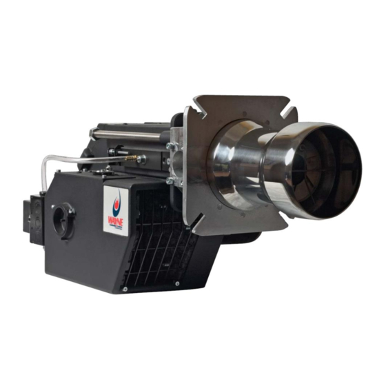
LC2300M
Gas Burner
Mounting Flange:
Air Tube Diameter:
Air Tube Insertions:
Flame Safety:
1
Fixed Flange
6.25 inches (159 mm)
8 inches (203 mm) Maximum with
9 inch (229 mm) Air Tube
Single-Rod Ionization
UV Scanner - 1000185-SER
(Optional))
Advertisement
Table of Contents
Troubleshooting

Related Manuals for Wayne LC2300M


Summary of Contents for Wayne LC2300M
- Page 1 WAYNE COMBUSTION SYSTEMS 801 GLASGOW AVE. LC2300M FORT WAYNE, IN 46803 PHONE: (260) 425-9200 (800) 443-4625 Gas Burner www.waynecombustion.com Manual 63899-002 | Revision A | Publication Date: 3/20/24 SPECIFICATIONS Burner Model: LC2300M Mounting Flange: Fixed Flange Minimum Input: 60,000 Btu/hr (17.5 kW) Air Tube Diameter: 6.25 inches (159 mm)
- Page 2 INSTALLATION LOG BURNER MODEL: SPECIFICATION FUEL (NATURAL GAS ORIFICE NUMBER: OR PROPANE): DRILLED SIZE: INLET GAS (%): (%): CO (PPM): PRESSURE (in. w.c.): INSTALLER’S NAME: CONTRACTOR CONTRACTOR CONTRACTOR NAME: ADDRESS: PHONE NUMBER: CONTRACTOR DATE OF LICENSE #: INSTALLATION: COMMENTS ABOUT INSTALLATION/START UP: BURNER/APPLIANCE SERVICE LOG SERVICE COMPANY...
- Page 3 The safety of you and others depends upon you thoroughly reading and understanding this manual. If you have questions or do not understand the information presented in this manual, please call Wayne Combustion Systems or see www.waynecombustion.com. This is the safety alert symbol. It is used to alert you to potential personal injury hazards. The meaning of this safety alert symbol is as follows: Attention! Become alert! Your safety may be at risk.
- Page 4 HAZARD PICTOGRAM TYPE HAZARD EXPLANATION LEVEL Fire or Failure to follow safety warnings exactly Explosion could result in serious injury, death or property damage. Do not store or use gasoline or other flammable vapors and liquids in the vicinity of this or any other appliance.
- Page 5 When contacting Wayne Combustion Systems Requirements for service information, please have the burner specification number and model number when calling or writing. IF ANY INSTRUCTIONS IN THE MANUAL ARE NOT CLEAR, CONTACT WAYNE COMBUSTION SYSTEMS AT 1-260-425-9200 FOR ASSISTANCE. 63899-002 Rev. A 3/20/2024...
-
Page 6: Table Of Contents
CONTENTS PAGE SECTION I INSTALLATION A. GENERAL B. VENTILATION C. MOUNTING TO EQUIPMENT D. GAS PIPING E. ELECTRICAL SUPPLY F. BURNER COMPONENTS G. MAIN BURNER INSTALLATION H. BURNER SETUP PRESSURE REGULATIONS ADJUSTMENT GAS PRESSURE SWITCHES SECTION II INITIAL START UP SECTION III OPERATION AND TROUBLESHOOTING A. -
Page 7: Section I Installation
ANSI or local installation code compliance is the sole responsibility of the qualified installer. B. VENTILATION The LC2300M burner models covered by this manual shall not be installed in an appliance located where normal air circulation or infiltration is limited in providing all the air necessary for proper combustion and draft hood dilution air. -
Page 8: Gas Piping
D. GAS PIPING NOTE: ALL PIPING MUST COMPLY WITH STATE AND/OR LOCAL CODES. THE AVAILABLE GAS SUPPLY PRESSURE SHOULD BE WITHIN THE MINIMUM AND MAXIMUM PRESSURES SHOWN IN THE BURNER SPECIFICATIONS. IF THE GAS SUPPLY PRESSURE EXCEEDS THE 48” W.C. (7 KPA) MAXIMUM, AN INTERMEDIATE MAIN GAS REGULATOR MUST BE INSTALLED AHEAD OF THE MAIN GAS MANUAL SHUTOFF VALVE. -
Page 9: Burner Components
F. BURNER COMPONENTS 1. Motor 2. Remote Electrical Box 3. Mounting Flange 4. Air Tube 5. Damper Motor - Gas 6. High Pressure Switch – Gas 7. Regulating Gas Valve 8. Safety Gas Valve 9. Double Valve Body 10. Low Pressure Switch – Gas 11. - Page 10 15. Ignition Transformer (Found Within Item #14 – Fixed Control Box) 16. Spark Electrode 17. Flame Rod 18. Air Plate 19. Nozzle 63899-002 Rev. A 3/20/2024...
- Page 11 20. LMV3 Control Unit 21. Motor Relay 22. Flame Boost Transformer F.1 LMV3 CONTROL UNIT The LMV control system is a control unit that can be used with various burner types. This unit is fully adjustable and is paired with multiple other system components. The LMV can be used for: 1.
- Page 12 F1-1 PRE-REQUISITES FOR BASIC LMV3 SYSTEMS Before the burner can be classified as in good working condition, there are various pre-requisites that must be met for the LMV control, burner, and application. 1. Burner must be in good condition, meaning; a.
- Page 13 Counterclockwise vs. Clockwise Rotation Figure 2 F.2-2 REFERENCE DIRECTION All SQM actuators have a limited range of motion between 0° - 90°. Means of operation mandates the actuator to re-home before each startup. This requires the actuator to rotate the “D”...
- Page 14 NOTE: IN MOST APPLICATIONS, VALVES AND DAMPERS CAN TYPICALLY ROTATE PAST THE OPEN POSITION (90°) WITHOUT INTERFERENCE. THEREFORE, IT IS MOST COMMON TO SET ALL ACTUATOR REFERENCE POSITIONS TO “OPEN”. F.3 AZL DISPLAY F.3-1 EXPLAINATION OF DISPLAY AND BUTTONS AZL Unit Figure 4 Button Function...
- Page 15 Meaning of AZL Icons Figure 5 To allow for installation flexibility, the AZL display is not pre-mounted on spec number 1000108-600. For panel cutout size, please reference Figure 6 below. Spec 1000108-400 and 1000108-401 contain the AZL display already mounted. AZL Dimensions 63899-002 Rev.
-
Page 16: Main Burner Installation
Figure 6 G. MAIN BURNER INSTALLATION The LC2300M power gas burners are approved for use with natural and LP gas only. G.1 GENERAL INSTRUCTION Installation must be completed in accordance with current instructions. The installer must be familiar with all regulations, so the installation meets the necessary requirements of the local authorities. - Page 17 Table 2: LC2300M with 1 ½’ Gas Line - L.P. Gas (Siemens VGD 1” Double Valve Body with SKP15 and SKP25 Regulators) Butterfly Firing Combustion Manifold Dimension Valve Gas Minimum Inlet “A” Rate Air Shutter Pressure Actuator Pressure (1000’s Setting (0-...
- Page 18 H.1 BURNER HEAD ADJUSTMENT: From Tables 1 and 2, find the Burner Head Setting (Dimension “A”) for the desired flow rate at which the burner will be operating. Referencing Figure 8, adjust the burner head by loosening the both the jam nut that locks the burner head adjusting screw and the black nut along the side of the burner.
- Page 19 Burner Head Adjustment Screw and Nut Burner Head Adjustment Figure 8 H.2 AIR SHUTTER ADJUSTMENT: The air shutter adjustment is programmed electronically in the settings of the AZL Display and may vary by application. Stock air shutter settings according to desired BTU/hr ratings are provided in Tables 1 and 2.
-
Page 20: Pressure Regulations Adjustment
H.5 ELECTRICAL CONNECTIONS: The installation must be wired and grounded in accordance with local codes or in their absence, with the National Electric Code ANSI/NFPA No. 70-2002 or latest edition. In CANADA, all wiring shall be done in accordance with the Canadian Electrical Code. H.6 SAFETY SYSTEM The safety system (Including hatches, doors, water levels, pressure, and temperature systems) must be installed according to current regulations. -
Page 21: Gas Pressure Switches
SECTION II – INITIAL START UP. J.3 GAS MODULATION – DIRECT SPARK IGNITION The LC2300M burner is classified as fuel train option 1. This option is pre-programmed into parameter 201 and allows full gas modulation, direct spark ignition and both air and gas actuators controlled electronically. -
Page 22: Section Ii Initial Start Up
SECTION II INITIAL START UP 1. Please note the applicable sequence of burner/primary gas control operation, gas pressure switches, etc. in SECTION III - OPERATION AND TROUBLESHOOTING before proceeding. 2. Lay out combustion test equipment, manometers, stopwatch, DC micro-amp meter, and other miscellaneous tools as needed. - Page 23 Before proceeding, HIGH FIRE AND LOW FIRE RATES HAVE BEEN PRE-SET BY THE MANUFACTURER. High fire is set for 2.3MMBtu. If the appliance rating is not capable of withstanding the pre-set high fire rate, please continue to step 10 for reprogramming. Otherwise, proceed to step 16. 10.
- Page 24 NOTE: TABLE 1 IN SECTION I – INSTALLATION REFERENCES VARIOUS SETPOINTS PRE-PROGRAMMED INTO THE AZL. FOR REPROGRAMMING P9 TO A LESSER FIRING RATE, USE THE TABLE AS A GUIDE FOR BOTH GAS AND AIR ACTUATOR SETTINGS FOR THE PROVIDED DURING RATES. 15.
- Page 25 Ph 24: Drive to pre-purge position Ph 30: Pre-Purge (Number on right of screen counts down from 30 seconds) Ph 36: Drive to ignition setpoint 18. Upon completion of the startup cycle, the screen will display the factory programmed or user re-programmed ignition set point as shown below.
- Page 26 After confirming all safety systems are in place and you are ready to ignite the burner, press the “+” button. The burner will go through the ignition cycle. Here, we will go thought Phase 38, 40, 42 and Ph 38: Pre-Ignition Ph 40: Initial safety.
- Page 27 NOTE: IF ADJUSTMENTS TO EITHER THE FUEL OR AIR SETTINGS ARE REQUIRED IN THE APPLICATION, THOSE ADJUSTMENTS MAY BE MADE BY HOLDING THE “F” FOR FUEL OR “A” FOR AIR BUTTONS WHILE SIMULTANEOUSLY USING THE “+” AND “-” ARROWS TO ADJUST ACCORDINGLY.
- Page 28 23. To view the flame sense value at any given set point, press and hold “Enter”. A value will be shown to the right of the screen from 0-100. Burner maintains optimal fire between 40-100% flame sense. Below 40% flame sense the burner may fault. Release the “Enter” key to resume normal screen. This can be done at any time throughout live firing.
- Page 29 COppm For Natural Gas: For Propane Gas: NOTE: THE LC2300M WAS DESIGNED TO FIRE INTO POSITIVE (UP TO 2.0 INCHES W.C.), NEUTRAL, OR SLIGHTLY NEGATIVE (UP TO –0.2 INCHES W.C.) COMBUSTION CHAMBERS. FOR OPTIMAL PERFORMANCE, CHECK OVERFIRE DRAFT AND ADJUST TO NEGATIVE -.01 (2.491PA) TO -.02 (4.982PA) INCHES W.C. DURING BURNER OPERATION IF POSSIBLE.
- Page 30 Gas Type Excess Air Flue Gasses (%O2) Natural Gas 4 ± 1 LP Gas 31. Adjust the High & Low Gas Pressure Switches according to actual firing conditions. For close burner control, the High Gas Pressure Switch should be set at approximately 1 in. W.C.
-
Page 31: Section Iii Operation And Troubleshooting
SECTION III OPERATION AND TROUBLESHOOTING A: SEQUENCE OF OPERATION Figure 11: LC2300M power gas burner utilizing Siemens LMV3 gas safety control and associated components Upon voltage (120VAC) being applied to the burner, the safety control will progress through phases 00, 02, and 10 which confirm proper functionality of the gas and air actuators and the individual safety circuits. - Page 32 A.1 PARAMETER LIST A list of the most common parameters used have been noted below, including all necessary login passwords. For a comprehensive list of LMV3 parameters and their functions, please refer to the LMV3 Technical Instructions beginning on page 52. A direct web link and QR code have been attached following on page 39.
- Page 33 Sets the fuel train. There are 29 possible options available. Setting Fuel Train 1-29 this parameter to undefined (----) will delete any existing fuel curves. If directly spark igniting the main fuel, this defines the overlap of the spark and the main fuel valves Safety Time 1 10 sec 1-10 sec...
- Page 34 provide additional information about the fault: Index 01 = code Index 02 = diagnostic Index 03 = class (not used in North America) Index 04 = phase Index 05 = start number Index 06 = load Index 07 = fuel (LMV36 only) 63899-002 Rev.
-
Page 35: Wiring Diagram
B: WIRING DIAGRAM 63899-002 Rev. A 3/20/2024... - Page 36 63899-002 Rev. A 3/20/2024...
-
Page 37: Flame Sensing With Equipped Controls
C: FLAME SENSING WITH EQUIPPED CONTROLS UTILIZING FLAME ROD SENSING The Siemens LMV3 controls equipped with flame rod sensing utilize the flame current rectification principle for main burner flame sensing. The burner is factory programmed to “High Sensitivity” (Parameter 197 = 1 and Parameter 198 = 2) to ensure the best flame sensing performance. The flame rectification phenomenon occurs as follows: The ignited gas flame causes the immediate atmosphere around the flame to become ionized (gas atoms become electrically charged). -
Page 38: Troubleshooting
easily be added into the system. The LMV3 compatible part number for purchase is 1000185-KIT. For wiring a UV scanner into the control, please reference the LMV3 Technical Instructions link and QR code found on Page 39. It is important to note that the sight glass must be removed when the UV kit is installed. -
Page 39: Adjusting Settings Of Previously Set Azl
Loc:d: This display shows the current diagnostic code. To reset the fault, press and hold “Enter” for 1…3s, rESEt will appear on the screen. When the button is released, the control unit is reset. NOTE: ABOVE REPRESENTS THE MOST COMMON FAULT CODES A USER MAY EXPERIENCE. - Page 40 3. Press and hold the two “VSD” buttons on the AZL display labeled “F” and “A” until the screen briefly displays “CodE” and then displays a series of dashes as shown below. Following the same steps as done in SECTION II - INITIAL SETUP. 4.
- Page 41 6. Now that parameter 201 has been changed back to dash (-), we are ready to re-assign a gas train type. With parameter 201 still displayed, press “Enter”. Toggle the “+” button to reassign the value to 1. Submit this value to the control by pressing “Enter” again. For direct ignition gas burners, the gas train type is 1.
- Page 42 15. Press simultaneously “F” and “+/-“ to set the ignition position of the fuel actuator. Your screen will appear as below. The dashes (- - -) to the right of the fuel value indicate that there is no value set for the air actuator.
- Page 43 Ph 12: Burner standby Ph 22: Burner, Safety Valve, and Fan Ph 24: Drive to pre-purge position Ph 30: Pre-Purge (Number on right of screen counts down from 30 seconds) Ph 36: Drive to ignition setpoint 21. Upon completion of the startup cycle, the screen will display the factory programmed ignition set point as previously programmed in Step 14.
-
Page 44: Backup And Restore
Ph 38: Pre-Ignition Ph 40: Initial safety. (Ignition transformer is energized.) At this point the spark electrode continues for 10 seconds. There will be a countdown to the right of the “Ph 40” display. Ph 42: Initial Safety. (Ignition transformer no longer energized) Ph 44: Phase 1 23. - Page 45 F.1 BACKUP Press “VSD” > 1 second to access login mode. You will need to log into the service level. See the Common Parameters Table in SECTION III for password. Toggle “+/-“ to Level 000. Press “Enter” Toggle “+/-“ to Parameter 050. Parameter 050 should begin flashing.
-
Page 46: Error History
Toggle “+/-“ to Parameter 050. Parameter 050 should begin flashing. Press “Enter” The screen will then display ”bAC_UP”. Press “+” to “Parameter rEStore”. The screen will display 0. Press “Enter”. Press “+” to change the 0 to a 1. The value 1 should be flashing. - Page 47 Index .01 = Error Code Index .02 = Diagnostic Code Index .03 = Error Class Index .04 = Error Phase Index .05 = Startup Counter Index .06 = Output Each index represents something different and allows for detailed diagnostic of the initial fault. Press “ESC”...
-
Page 48: Section Iv Service
SECTION IV SERVICE Make sure that the main gas valves and electrical power disconnect are turned off before opening the burner or removing any parts for service. All cover plates, enclosures, and guards must always be in place, except during maintenance and servicing. - Page 49 Figure 13 3. Remove the cover from the fan housing, see Figure 13. Figure 14 4. Disconnect the ignition wire, sensing probe wire, and ground wire of the gun assembly. Ignition Wire Ground Wire Sensing Wire Figure 15 63899-002 Rev. A 3/20/2024...
- Page 50 5. Remove the nut on the right side of the burner housing, see Figure 16. Figure 16 6. Remove the two nuts on either side of the burner housing, see Figure 17. Figure 17 7. Loosen screw on the left side of the burner head assembly, see Figure 18. Figure 18 63899-002 Rev.
-
Page 51: Air Proving Switch
8. Pull the burner body straight back along the slides until you get a gap of approximately 8 inches. The burner head assembly can now be removed, see Figure 19. Figure 19 When servicing, clean burner head ports, electrodes and sensor probe. Inspect the sensor probe and electrode wires and ceramic insulators carefully for hairline cracks, which might provide an electrical leak path that could short out the ignition spark, or flame signal. -
Page 52: Combustion Air Blower And Motor
If a jumper is used to check the switch, the jumper MUST be removed, and the Air Proving Switch reconnected or an unsafe condition can occur resulting in PERSONAL INJURY OR DEATH E: COMBUSTION AIR BLOWER AND MOTOR Cleaning of the combustion air blower is required if the blades show an accumulation of dust and lint, or if the character of the flame indicates a deficiency of combustion air. -
Page 53: Section V Technical Information
TECHNICAL INFORMATION A: NUISANCE LOCKOUTS/FLAME SENSING PROBLEMS Wayne’s LC2300M series gas burners utilize a flame rod or prove flame through the process of flame rectification. One of the most common problems with gas appliances utilizing this type of electronic flame sensing system is the “nuisance lockout”. - Page 54 7. The burner body is not properly grounded to the burner head. Check to ensure the ground wire is properly connected to the ground tab on the burner head assembly and the ground tab on the burner body, see Figure 15. 8.
- Page 55 Once all the items listed previously have been checked and corrected as necessary, reinsert the gas train assembly into the burner. NOTE: BE CAREFUL NOT TO ACCIDENTALLY REPOSITION EITHER THE FLAME ROD PROBE OR ELECTRODE DURING REINSTALLATION OF THE GAS TRAIN ASSEMBLY.
-
Page 56: Section Vi Drawings And Parts List
SECTION VI DRAWINGS AND PARTS LIST NOTE: A parts list for your gas burner can be generated directly from the Wayne Combustion Systems’ website. Visit our website at www.waynecombustion.com. Enter the “Specification Number” of your gas burner in the “Product Search” box. Click on “Search” and follow the results page to a product parts list. Print the product parts list for your reference by clicking on the “Print This Page”... - Page 57 63899-002 Rev. A 3/20/2024...
- Page 58 63899-002 Rev. A 3/20/2024...
- Page 59 63899-002 Rev. A 3/20/2024...
- Page 60 63899-002 Rev. A 3/20/2024...
-
Page 61: Section Vii Consumer Instructions
SECTION VII CONSUMER INSTRUCTIONS Keep the area around the burner clear and free of combustible materials, gasoline or other flammable liquids or vapors. Do not obstruct burner air openings or ventilation grilles for combustion air. If the burner is to be shut down for an extended time, the main manual gas valve should be closed as a precaution. -
Page 62: Warranty
Also, some states do not allow the sole option. exclusion or limitation of incidental or consequential WAYNE is not responsible for any labor cost for the damages, so the above limitation or exclusion may not removal and replacement of said burner or burner apply to you. - Page 63 This page intentionally left blank 63899-002 Rev. A 3/20/2024...
- Page 64 NOTES 63899-002 Rev. A 3/20/2024...
Need help?
Do you have a question about the LC2300M and is the answer not in the manual?
Questions and answers