Table of Contents
Advertisement
Quick Links
A SCOTT FETZER COMPANY
801 GLASGOW AVE.
FORT WAYNE, IN 46803
US PATENT NO. 4,388,064
WARNING: If the information in these instructions
is not followed exactly, a fire or explosion may result
causing property damage, personal injury or death.
- Do not store or use gasoline or other flammable
vapors and liquids in the vicinity of this or any other
appliance.
- WHAT TO DO IF YOU SMELL GAS
• Do not try to light the appliance.
• Do not touch any electrical switch; do not use any
phone in your building.
• Immediately call your gas supplier from a
neighbor's phone. Follow the gas supplier's
instructions.
• If you cannot reach your gas supplier, call the fire
department.
- Installation and service must be performed by a
qualified, licensed installer, service agency or the gas
supplier. WARRANTY IS VOIDED IF NOT
INSTALLED BY QUALIFIED SERVICE PERSON.
THESE INSTRUCTIONS SHOULD BE AFFIXED TO THE BURNER
OR ADJACENT TO THE HEATING APPLIANCE.
FOR FURTHER INSTRUCTIONS AND WARNINGS,
NOTICE
SEE PAGE 21 OF THIS MANUAL.
SPECIFICATIONS
[SEE PAGE #1]
Publication Date 6/11/07
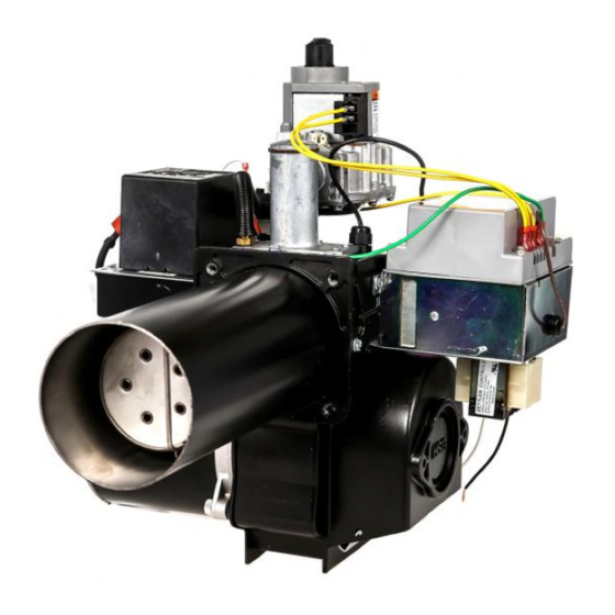
MODELS
HSG200
HSG400
GAS BURNERS
120V/50-60 HZ
220V/50 HZ
PART NO. 62484-001B
MEA
MASS.
ANSI Z21.17
APPROVED
FOR USE CITY
OF NEW YORK
MEA 49-83-E
Advertisement
Table of Contents

Related Manuals for Wayne HSG200


Summary of Contents for Wayne HSG200
-
Page 1: Specifications
MODELS HSG200 HSG400 A SCOTT FETZER COMPANY GAS BURNERS 801 GLASGOW AVE. FORT WAYNE, IN 46803 120V/50-60 HZ 220V/50 HZ PART NO. 62484-001B US PATENT NO. 4,388,064 WARNING: If the information in these instructions is not followed exactly, a fire or explosion may result causing property damage, personal injury or death. -
Page 2: Table Of Contents
SPECIFICATIONS MODELS HSG200, HSG400 NATURAL OR PROPANE GAS NOTE: Dimensions in ( ) are informational only. English values take priority. HSG200 Maximum Input Capacity - 200 MBtu/HR (211000 kJ) Minimum Input Capacity - 60 MBtu/HR (63300 kJ) HSG400 Maximum Input Capacity - 400 MBtu/HR (422000 kJ) Minimum Input Capacity - 200 MBtu/HR (211000 kJ) SUPPLY LINE PRESSURE REQUIRED: Natural or Propane 5.5 W.C. -
Page 3: Section I Installation
Power burner design makes the HSG200 and those required by this burner and that they are in HSG400 well suited for “negative draft” fired proper working order. - Page 4 Pitch the horizontal run of the flue pipe upward 1/4 inch The draft control should be hood type per Figure 2 or, IF (6.35mm) per foot (.305m) or more. Run directly to the APPROVED BY LOCAL AUTHORITIES, a single chimney, fasten joints securely and support horizontal barometric damper suitable for gas firing per Figure 3.
-
Page 5: Combustion Chamber
E. COMBUSTION CHAMBER F. GAS PIPING NOTICE: All piping must comply with state and/or A combustion chamber is normally required to local codes. The available gas supply pressure protect non-heat transfer surfaces, and to provide a should be within minimum and maximum pressures radiant bed for rapid heat transfer to the primary shown in the burner specifications. -
Page 6: Electrical
AND INSTALLATION The installation must be wired and GROUNDED in accordance with local codes or in their absence, The HSG200 and HSG400 power gas conversion with the National Electric Code ANSI/NFPA No. 70- burners are approved for use with natural and 1987 or latest edition. -
Page 7: Combustion Gas Valve
COMBINATION GAS VALVE approximately 2.0” W.C. (498.2Pa) to 4.0” W.C. (996.4Pa) is factory set at 3.5” W.C (871.85Pa). The 24 VAC combination gas valve serves three (3) When pressure adjustment is required for setting functions: (1) manual gas shut-off, (2) main gas input capacity with a selected orifice from Figure 10, flame pressure regulator, (3) automatic electric remove the regulator cap for access to the slotted... -
Page 8: Section Ii Initial Start Up
SECTION II INITIAL START UP 1. NOTE: Read applicable sequence the primary air damper open or closed to visually burner/primary gas control operation in obtain a blue flame with well defined orange or Section 3 Operation and Troubleshooting yellow tips for natural gas, or well defined yellow tips before proceeding. - Page 9 CAUTION: IF THE BURNER BTU/HR (kW/Hr) INPUT IS CHANGED, REPEAT STEP 13 the back of this manual or the instruction plate attached to the burner. 3/8” (9.525mm) HSG200 SET AT NO. 1 HSG400 SET AT NO. 1 1/2 Figure 12A Figure 12B IMPORTANT THESE SETTINGS ARE FOR INITIAL STARTUP ONLY, AND MUST BE READJUSTED FOR COMBUSTION EFFICIENCY.
-
Page 10: Section Iii Operation And Troubleshooting
SECTION III OPERATION AND TROUBLESHOOTING SEQUENCE OF OPERATION - HSG SERIES POWER GAS CONVERSION BURNER UTILIZING HONEYWELL S89F GAS PRIMARY P/N 62759-002 W/BUILT IN 30 SECOND PREPURGE On a call for heat, voltage (24V) is applied to motor start the flame rod will provide flame monitoring to the S89F relay and air switch. - Page 11 SEQUENCE OF OPERATION - HSG SERIES POWER GAS CONVERSION BURNER UTILIZING HONEYWELL S89E GAS PRIMARY P/N 62758-002 W/ EXTERNAL 30 SECOND PREPURGE TIMER P/N 62388-001 AND RESISTOR P/N 62530-001 On a call for heat, voltage (24V) is applied to the motor second prepurge timer and the input terminal to the start relay and air switch.
- Page 12 FLAME SENSING The Honeywell S89 series primary ignition controls through the ionized gas flame to the grounded burner utilize the flame current rectification principal for main head. As the AC current passes through the gas flame, burner flame sensing. it is rectified into a DC current flowing back to the grounded side of the sensing circuit.
- Page 13 PAGE 12...
- Page 14 PAGE 13...
- Page 15 PAGE 14...
-
Page 16: Section Iv Service
The air proving switch is mounted to the housing cover with (2) #6 self tapping screws under the gas HSG200 blower wheel p/n 21664 is positioned valve. A clear plastic tube, protected by a spring 2 1/16” (52.3875mm) measured from the blower cover, is connected to the barbed fitting on the wheel inlet ring face to the side plate face. - Page 17 DRAWER ASSEMBLY Figure 15 PART NUMBER DIM “A” 21664 HSG200 2 1/16” 5 1/4 O.D. (52.3875mm) (133.35mm) 21642 HSG400 2 3/16” 5 1/2 O.D. (55.5625mm) (139.7mm) MOTOR/BLOWER ASSEMBLY Figure 16 PAGE 16...
-
Page 18: Parts Lists
Air Cone - (HSG200 only) 21724-011 Adjustable Flange Assembly (includes gasket)(not shown) 100428-002 Flange Gasket (not shown) 21664 Blower Wheel HSG200 5 1/4" OD (133.35mm) 21642 Blower Wheel HSG400 5 1/2" OD (139.7mm) 21658 Side Plate (Used with 20627 and 20627-004 Motors Only) 20627 Motor, Split Phase 1/7 (.107kW) or 1/8 (.093kW) HP 3450 RPM 115V/60... -
Page 19: Exploded View
PAGE 18... -
Page 20: Technical Information
TECHNICAL INFORMATION “Troubleshooting Guide” NUISANCE LOCKOUTS/FLAME SENSING PROBLEMS - HSG200 & HSG400 GAS BURNERS Wayne’s HSG series direct spark ignition (DSI) gas burner head with approximately 1/16” (1.5875mm) burners prove flame through the process of flame clearance from the head. The probe must not be rectification. -
Page 21: Warranty
LIMITED WARRANTY by WAYNE shall be repaired or replaced at WAYNE’s sole option. 3. WAYNE is not responsible for any labor cost for the removal and replacement of said burner or burner components and equipment associated therewith. -
Page 22: Consumer Instructions
CONSUMER INSTRUCTIONS A dangerous condition has developed and must be corrected. MAINTENANCE: ■ Keep the area around the burner clear and free of com- CONTACT A QUALIFIED SERVICE TECHNICIAN FOR CLEANING, READJUSTMENT OR REPAIR. bustible materials, gasoline or other flammable liquids or LIGHTING INSTRUCTIONS: vapors. - Page 23 Notes PAGE 22...
Need help?
Do you have a question about the HSG200 and is the answer not in the manual?
Questions and answers