Table of Contents
Advertisement
WAYNE COMBUSTION SYSTEMS
www.waynecombustion.com
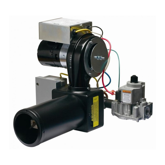
P250AF Gas Burner
BURNER MODELS
P250AF & P250AF-EP & P250AFDI
P265 & P265EP & P265DI
P265F & P265FEP &P265FDI
ELECTRICAL Power Supply – 115V/60HZ 1 Ph.
INSTALLATION OF THE BURNER MUST BE DONE BY A QUALIFIED INSTALLER IN ACCORDANCE WITH
REGULATIONS OF THE NATIONAL FUEL GAS CODE ANSI Z223.1/NFPA 54, AND IN COMPLETE ACCORDANCE WITH
ALL LOCAL CODES AND AUTHORITIES HAVING JURISDICTION.
INCORRECT INSTALLATION, ADJUSTMENT, OR MISUSE OF THIS BURNER WILL VOID THE WARRANTY
AND COULD RESULT IN DEATH, SEVERE PERSONAL INJURY, OR SUBSTANTIAL PROPERTY DAMAGE.
A QUALIFIED INSTALLER IS THE PERSON WHO IS RESPONSIBLE FOR THE INSTALLATION AND ADJUSTMENT OF
THE EQUIPMENT AND WHO IS LICENSED TO INSTALL GAS-BURNING EQUIPMENT IN ACCORDANCE WITH ALL
CODES AND ORDINANCES.
BURNER IS SHIPPED AT MINIMUM RATE AND MAX AIR
801 GLASGOW AVE.
FORT WAYNE, IN 46803
PHONE: (260) 425-9200
(855) WAYNECS
(800) 443-4625
FAX: (260) 424-0904
Manual 101220 | Revision C | Publication Date: 7/11/14
NOTE: Dimensions in () are informational only. English values take priority.
SPECIFICATIONS
MINIMUM INPUT
50,000 Btu/hr (15 kW)
65,000 Btu/hr (19 kW)
65,000 Btu/hr (19 kW)
If the information in these instructions is not followed exactly, a fire or
explosion may result causing property damage, personal injury or death.
INSTALLATION OF BURNER
LIGHT IN THIS CONFIGURATION AND WILL NEED AIR ADJUSTMENT
CSA CERTIFICATE NUMBER: 1156769
MODELS
ALL P250 AND P265 SERIES
GAS BURNERS
P265F Gas Burner
MAXIMUM INPUT
250,000 Btu/hr (73 kW)
200,000 Btu/hr (59 kW)
200,000 Btu/hr (59 kW)
MOUNTING: Adjustable Flange is Standard; Pedestal Mount is Optional
FUELS
Natural & L.P. Gas
Natural & L.P. Gas
Natural & L.P. Gas
BURNER MAY NOT
Advertisement
Table of Contents
Troubleshooting

Related Manuals for Wayne P250 series


Summary of Contents for Wayne P250 series
-
Page 1: Specifications
MODELS WAYNE COMBUSTION SYSTEMS 801 GLASGOW AVE. FORT WAYNE, IN 46803 PHONE: (260) 425-9200 ALL P250 AND P265 SERIES (855) WAYNECS (800) 443-4625 FAX: (260) 424-0904 GAS BURNERS www.waynecombustion.com Manual 101220 | Revision C | Publication Date: 7/11/14 NOTE: Dimensions in () are informational only. English values take priority. - Page 2 INSTALLATION LOG BURNER MODEL: SPECIFICATION NUMBER: FUEL (NATURAL OR GAS ORIFICE DRILLED PROPANE): SIZE: INLET GAS PRESSURE (%): (%): CO (PPM): (in. w.c.): INSTALLER’S NAME: CONTRACTOR NAME: CONTRACTOR CONTRACTOR PHONE ADDRESS: NUMBER: CONTRACTOR LICENSE #: DATE OF INSTALLATION: COMMENTS ABOUT INSTALLATION/START UP: BURNER/APPLIANCE SERVICE LOG SERVICE COMPANY...
- Page 3 FOR YOUR SAFTEY: DO NOT STORE OR USE GASOLINE OR OTHER FLAMMABLE VAPORS AND LIQUIDS IN THE VINCINITY OF THIS OR ANY OTHER APPLIANCE. WHAT TO DO IF YOU SMELL GAS: Open Windows. Do not try to light any appliances. ...
-
Page 4: Table Of Contents
CONTENTS PAGE SECTION I INSTALLATION AND SETUP………………………………………………………………………………………. A. VISUAL INSPECTION OF THE HEATING SYSTEM………………………………………………………………….. B. INSPECTION OF FLUE PIPE AND CHIMNEY………………………………………………………………………… C. INSPECTION OF HEATING APPLIANCE…………………………………………………………………………….. D. FLUE PIPE, DRAFT HOOD, AND BAROMETRIC DAMPER……………………………………………………….. E. PREPARATION OF COMBUSTION CHAMBER……………………………………………………………………… F. SIZING OF COMBUSTION CHAMBER………………………………………………………………………………… G. - Page 5 E. PRELIMINARY CHECK, DIAGNOSIS AND SERVICE HINTS(ELECTRONIC PILOT IGNITION)…………… 30 F. COMPONENT TROUBLESHOOTING AND DIAGNOSIS………………………………………………………… 31 G. MORE SERVICE HINTS……………………………………………………………………………………………… 32 H. P250AF/P265F IGNITOR POSITION………………………………………………………………………………. 33 P250AF/P265F WIRING DIAGRAMS………………………………………………………………………………. 34 SECTION VI PARTS LIST AND EXPLODED VIEWS ………..……………………………………………………………. 39 A. P265F EXPLODED VIEWS………………………………………………………………………………………….. 39 B.
-
Page 6: Section I Installation And Setup
SECTION I: INSTALLATION AND SETUP These instructions were prepared for the guidance of those installing this particular gas conversion burner. While they apply in principle to all installations, they should not be interpreted as meaning the only safe and economical way to install a conversion burner. It may be necessary to deviate from these instructions in some instances in order to comply with local gas company rules or codes in effect in the area in which the installation is made. -
Page 7: Inspection Of Flue Pipe And Chimney
The heating system (both the heat exchanger and distribution system) shall be of a size to properly heat the building. Throug h inquiry it shall be determined that all rooms have been heated adequately without wide variations in temperature, without objectionable drafts, and without excessive fuel costs in the past. -
Page 8: Inspection Of Heating Appliance
INSPECTION OF HEATING APPLIANCE Clean the appliance heat exchanger interior, combustion chamber and flue connections. Remove all adhering tars, scale, dirt, and soot. Inspect the heat exchanger for obvious and potential flue gas leaks. Cement all joints around the appliance base and access openings to prevent air and/or flue gas leakage into or out of the combustion chamber. - Page 9 The flue pipe should be relocated where possible to avoid sharp turns. DRAFT – When installing Wayne power gas burners in oil fired boilers a minimum negative draft of .02” (5 Pa) w.c. over fire must be maintained. Refer to your local gas company and codes for assistance.
-
Page 10: Preparation Of Combustion Chamber
PREPARATION OF COMBUSTION CHAMBER Clean the combustion chamber thoroughly. Scrape and brush all heating surfaces and flue ways. Soot and fly ash are excellent insulators and unless removed, the efficiency of the heating appliance will be impaired. Plugged or restricted flue passages will prevent burner from operating properly. -
Page 11: Sizing Of Combustion Chamber
SIZING OF COMBUSTION CHAMBER The following tables are provided as a guideline for determining combustion chamber size and corresponding firing rate when appliance rates are not available. Table 1: Combustion Chamber for P250 Only Input Floor Area Preferred Width and Length Btu/hr (kW) Sq. -
Page 12: Burner Installation
BURNER INSTALLATION The P250 and P265 power gas burners were designed for converting oil fired furnaces and boilers. Due consideration was given to making it as simple and easy to install and service as possible without weakening its durability or efficiency. The burner is supplied as a completely assembled package unit. -
Page 13: Determine Orifice Size And Rate
DETERMINE ORIFICE SIZE AND RATE The gas conversion burner needs to be set to deliver the same amount of heat to the appliance as the oil burner it is replaci ng. Determine the Btu/hr heat input rate for the appliance by locating the rating plate of the appliance and determine the firing rate of the oil burner. - Page 14 NOTE: The Btu/hr input values in Table 4 show the approximate hourly input of the burner for the various drill bit sizes shown. To determine the actual input of the burner by using the gas meter, follow these steps: 1) Turn off all other gas appliances. 2) The hand on the dial with the lowest cubic feet value (fastest revolving dial) should be clocked for one complete revoluti on.
- Page 15 Pull the gas train out of the burner. The orifice is located on the end of the gas train and looks like a brass plug. Remove the orifice with a 11/16 inch wrench (Figure 8). FIGURE 8: ORIFICE LOCATION To drill the orifice, place it face down in a vice and drill through the back side. The back side is tapered and will make lining up the drill bit easier.
-
Page 16: Inspection And Sizing Of Gas Piping
INSPECTION AND SIZING OF GAS PIPING All piping must comply with local codes and ordinances or the National Fuel Gas Code ANSI Z223.1/NFPA No. 54. A sediment trap or drip leg must be installed in the supply line to the burner. A union shall be installed in the gas line upstream from the con trol manifold and downstream from the sediment trap or drip leg (See Figure 10). - Page 17 supply piping system by closing its individual manual shutoff valve during any pressure testing of the gas supply piping system at test pressures equal to or less than 1/2 psig (3447 PaG). Table 5: Pipe Sizing Chart for Natural Gas (0-0.5 psi) with Straight Schedule 40 Metal Pipe The following chart is based on 0-0.5 psi inlet pressure, specific gravity of 0.6, and a pressure loss of 0.5”...
-
Page 18: Testing Piping For Leaks
Table 7: Pipe Sizing Chart for Liquid Propane (11” w.c.) with Copper Tubing The following chart is based on 11” w.c. inlet pressure and a pressure drop of 0.5” w.c.. Maximum Capacity of Tube Size in Btu per Hour Pipe Size 1/2”... -
Page 19: Inspection Of Limit Control Switches
INSPECTION OF LIMIT CONTROL SWITCHES Warm air furnaces (gravity and forced air) should be equipped with an automatic temperature limit control switch. Hot water boilers (forced or gravity) should be equipped with an automatic temperature limit control switch. Steam or vapor boilers be provided with means to guard against firing a dry boiler or one in which the water is dangerously low. -
Page 20: Section Ii Initial Start Up
SECTION II: INITIAL START UP OPERATION OF BURNER (DIRECT SPARK IGNITION) Starting the Burner: Depress the gas valve control knob on the combination gas valve and turn to “OFF” (See Figure 13). Set the room thermostat above room temperature and let the burner run five minutes to purge the appliance. Set thermostat below room temperature. -
Page 21: Operation Of Burner (Electronic Pilot)
OPERATION OF BURNER (ELECTRONIC PILOT) (P265-EP, P265F-EP, P250AF-EP) Starting the Burner: Depress the gas valve control knob on the combination gas valve and turn to “OFF” (See Figure 14). Set room thermostat above room temperature and let burner run five minutes to purge the appliance. Set thermostat below room temperature. -
Page 22: Operation Of Burner (Standing Pilot)
OPERATION OF BURNER (STANDING PILOT) Starting the Burner: Depress the gas valve control knob on the combination gas valve and turn to “OFF” (See Figure 15). Set room thermostat above room temperature and let burner run five minutes to purge the appliance. Set thermostat below room temperature. -
Page 23: Combustion Adjustment Of Burner
COMBUSTION ADJUSTMENT OF BURNER All adjustments below must be made with the following equipment: 1. Draft Gauge 3. CO Tester 2. O or CO Analyzer 4. Water Column Gauge Flame Spreader Adjustment (P250AF Only) The flame spreader is used to shape the flame to best suit the firing chamber. Depending on the firing chamber, the flame spreader can be used to produce a long narrow flame or a short bushy flame. -
Page 24: Final Installation Instructions
In order to allow P250 and P265 burners to be converted from natural gas to LP gas operation, or from LP to natural gas operation, Wayne Combustion Systems has created gas conversion kits that contain all the parts necessary for any burner model regardless of the type of ignition system utilized;... -
Page 25: Section Iv Consumer Instructions
In addition to the necessary parts to complete the gas conversion, each kit contains detailed instructions for the conversion. To order the appropriate gas conversion kit, please contact a local wholesaler. The Wayne Combustion Customer Service Department can assist in locating the nearest wholesaler. -
Page 26: Section V Service And Troubleshooting
SECTION V: SERVICE AND TROUBLESHOOTING NORMAL OPERATION CHECK OF BURNER (DIRECT IGNITION) APPLIANCE CALLS FOR HEAT BY RAISING THE THERMOSTAT TO THE DESIRED SETTING: Note the transformer is always energized with 110 volts. When the thermostat circuit is complete, this allows 24 volts to coil side of the fan relay which are the bottom terminals. Now that 24 volts (yellow wires) are applied to the coil, this in turn allows the 115 volt contacts to close thus allowing 115 volts to flow to the fan across terminals #2 and #4 which are in series with the fan motor. -
Page 27: Normal Operation Check Of Burner (Electronic Pilot)
NORMAL OPERATION CHECK OF BURNER (ELECTRONIC PILOT) PRELIMINARY CHECK The following visual checks should be made before troubleshooting an after installation or maintenance. 1. Check the power to the appliance and S8600. 2. Manual shutoff cocks in gas line to appliance must be open. 3. -
Page 28: Troubleshooting Guide Direction Ignition
9. OPEN END WRENCHS 10. TAPE MEASURE The Wayne Burner that you are attempting to troubleshoot has the following electrical single phase components: 1. 115 Volt Combustion Fan Motor with End Switch 2. Fan Relay-24 volt coil side and 110 volt fan side 3. - Page 29 START TURN GAS SUPPLY OFF, TURN THERMOSTAT (CONTROLLER) Check line voltage power, low voltage transformer, limit controller, thermostat TO CALL FOR HEAT (controller) and wiring. Also check end switch on combustion air blower system. POWER TO MODULE (24V NOMINAL) - Check ignition cable, ceramic insulator and gap, and replace part if necessary. SPARK ACROSS - Check boot of the ignition cable for signs or melting or buckling.
-
Page 30: Preliminary Check, Diagnosis And Service Hints(Electronic Pilot Ignition)
Table 8: Troubleshooting Chart Electronic Pilot Ignition (For Burners Utilizing Fenwal Control) Symptoms Possible Causes a. Air in gas line. b. High or low gas pressure. 1. PILOT DOES NOT LIGHT. c. Blocked pilot orifice. d. Broken or damaged ignition cable. a. -
Page 31: Component Troubleshooting And Diagnosis
voltage, it should be replaced. If the voltage is not present at Terminals PV1 and ground (or across valve), the control should be replaced. Electrode Placement a. Electrode should be placed so optimum flame current is achieved for proper application. b. -
Page 32: More Service Hints
IGNITER ROD The igniter rod is responsible for conveying the spark to a grounding rod in an appropriate location to ignite the gas and air mix. The igniter rod gap should be 1/8”, larger gaps will create ignition problems. If the igniter rod is cracked, sparking sound will be heard inside the burner air tube but ignition will not occur and lockout will occur. -
Page 33: P250Af/P265F Ignitor Position
FIGURE 21... -
Page 34: P250Af/P265F Wiring Diagrams
WIRING DIAGRAMS CAUTION: Label all wires prior to disconnection when servicing controls. Wiring errors can cause improper and dangerous operation. Verify proper operation after servicing. FIGURE 22: WIRING DIAGRAMS FOR GAS BURNER WITH DIRECT IGNITION-HONEYWELL... - Page 35 FIGURE 23: WIRING DIAGRAMS FOR GAS BURNER WITH DIRECT IGNITION-FENWAL...
- Page 36 FIGURE 24: WIRING DIAGRAMS FOR GAS BURNER WITH ELECTRONIC PILOT-HONEYWELL...
- Page 37 FIGURE 25: WIRING DIAGRAMS FOR GAS BURNER WITH ELECTRONIC PILOT-NO T-STAT...
- Page 38 FIGURE 26: WIRING DIAGRAMS FOR GAS BURNER WITH ELECTRONIC PILOT-FENWAL...
-
Page 39: Section Vi Parts List And Exploded Views
SECTION VI: PARTS LIST AND EXPLODED VIEWS Parts in Exploded View 1. Gas Valve 2. Air Shutter 3. Motor/Blower 4. Transformer 5. Model/Specification Label 6. Motor Relay 7. Ignition Control 8. Electrode/Sensor/Ground Rod Asm 9. T-T Terminal 10. Orifice Holder 11. - Page 40 Parts in Exploded View 1. Gas Valve 2. Air Shutter 3. Motor/Blower 4. Transformer 5. Model/Specification Label 6. Motor Relay 7. Ignition Control 8. Electrode/Sensor/Ground Rod Asm 9. T-T Terminal 10. Orifice Holder 11. Orifice 12. Flame spreader FIGURE 28: Left Side Exploded View of P265F...
-
Page 41: P265F Parts List
P265F PARTS LIST Item Description *NOTE: Only for firing rate of 160,000 Part No. Btu/hr or less when finer adjustment at low rate is required. Req’d 60172-002 Motor/Blower Asm (w/o Control Box) 61803 Control Box Asm (Incl. Trans. & Relay) ... -
Page 42: P250Af Exploded Views
Parts in Exploded View 1. Gas Valve 2. Air Shutter 3. Motor/Blower 4. Transformer 5. Model/Specification Label 6. Motor Relay 7. Ignition Control 8. Electrode/Sensor/Ground Rod Asm 9. T-T Terminal 10. Orifice Holder 11. Orifice 12. Flame spreader FIGURE 29: Right Side Exploded View of P250AF... - Page 43 Parts in Exploded View 1. Gas Valve 2. Air Shutter 3. Motor/Blower 4. Transformer 5. Model/Specification Label 6. Motor Relay 7. Ignition Control 8. Electrode/Sensor/Ground Rod Asm 9. T-T Terminal 10. Orifice Holder 11. Orifice 12. Flame spreader FIGURE 30: Left Side Exploded View of P250AF...
-
Page 44: P250Af Parts List
P250AF PARTS LIST Item Description *NOTE: Only for firing rate of 160,000 Part No. Btu/hr or less when finer adjustment at low rate is required. Req’d 60172-002 Motor/Blower Asm (w/o Control Box) 61803 Control Box Asm (Incl. Trans. & Relay) ... -
Page 45: Section Vii Warranty
WAYNE is not responsible for any labor cost for the apply to you. WAYNE neither assumes or authorizes removal and replacement of said burner or burner any person to assume for WAYNE any other liability or components and equipment associated therewith. - Page 46 NOTES...
Need help?
Do you have a question about the P250 series and is the answer not in the manual?
Questions and answers