Otto Bock Genium 3B1-3 Instructions For Use Manual
Hide thumbs
Also See for Genium 3B1-3:
- User instructions (75 pages) ,
- Instructions for use manual (108 pages) ,
- Instructions for use manual (60 pages)

Related Manuals for Otto Bock Genium 3B1-3


Summary of Contents for Otto Bock Genium 3B1-3
- Page 1 Genium 3B1-3 / 3B1-3=ST Instructions for use (user) ....................
- Page 2 order-ifu@ottobock.com Documentu 647H45 Versionu 09 SCAN ME httpsu//product-documents.ottobock.com/IFU/IVT/3B1-3/647H45/09/O/S/F DE | Lassen Sie sich durch das Fachpersonal in den sicheren Gebrauch des Produkts einweisen. Weitere Sprachen dieser Gebrauchsanweisung sind online verfügbar oder können kostenlos als gedrucktes Exemplar bestellt werden (siehe Seite 2). EN | Consult qualified personnel for instructions on how to use the product safely.
- Page 3 NO | La fagpersonell instruerer deg i sikker bruk av produktet. Flere språk for denne bruksanvisningen er tilgjengelige på nett, eller de kan bestilles som utskrevet eksemplar (se side 2). FI | Anna ammattihenkilöstön perehdyttää itsesi tuotteen turvalliseen käyttöön. Tämän käyttöohjeen muut kielet ovat saatavilla online tai niitä voi tilata maksutta painettuna versiona (katso sivu 2).
-
Page 5: Table Of Contents
Table of contents Foreword ......................... Product description ....................... Design ........................ Function ......................Application ........................Indications for use ....................Conditions of use ....................Indications ......................Contraindications ....................3.4.1 Absolute Contraindications .................. 3.4.2 Relative Contraindications ................... Qualification ...................... Safety ..........................Explanation of warning symbols ................ - Page 6 7.4.3 Connecting component with multiple mobile devices ....................................Movement patterns in basic mode (mode 1) ............8.1.1 Standing ......................8.1.1.1 Stance function ....................8.1.2 Walking ......................8.1.3 Running short distances ("walk-to-run" function) ............ 8.1.4 Sitting down ...................... 8.1.5 Sitting .......................
- Page 7 14.2 Trademarks ....................... 14.3 CE conformity ....................14.4 Local Legal Information ..................Technical data ......................Appendices ........................16.1 Symbols Used ....................16.2 Operating states/error signals ................16.2.1 Signals for operating states ................. 16.2.2 Warnings/error signals ..................16.2.3 Error messages while establishing a connection with the cockpit app .......
-
Page 8: Foreword
1 Foreword INFORMATION Date of last update: 2023-10-05 Please read this document carefully before using the product and observe the safety ► notices. Obtain instruction from the qualified personnel in the safe use of the product. ► Please contact the qualified personnel if you have questions about the product or in case of ►... -
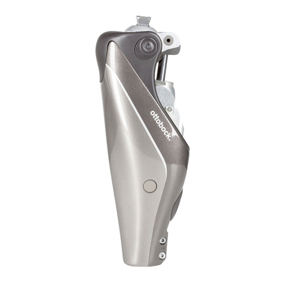
Page 9: Function
2.2 Function This product features microprocessor control of the stance and swing phase. The microprocessor uses the measurements of an integrated sensor system as a basis to control a hydraulic unit that influences the damping behaviour of the product. These sensor data are updated and evaluated 100 times per second. As a result, the behaviour of the product is adapted to the current motion situation (gait phase) dynamically and in real time. -
Page 10: Indications
3.3 Indications • For users with knee disarticulation, transfemoral amputation or hip disarticulation. • For unilateral or bilateral amputation • Dysmelia patients with residual limb characteristics corresponding to knee disarticulation, transfemoral amputation or hip disarticulation • The user must fulfil the physical and mental requirements for perceiving optical/acoustic sig nals and/or mechanical vibrations 3.4 Contraindications 3.4.1 Absolute Contraindications... - Page 11 All users are required to observe their country’s national and state driving laws when operat ► ing vehicles with a prosthesis. For insurance purposes, drivers should have their driving ability examined and approved by an authorised test centre. Observe national legal regulations for retrofitting your vehicle in accordance with the type of ►...
- Page 12 CAUTION Mechanical stress on the product > Falling due to unexpected product behaviour as the result of a malfunction. > Falling due to breakage of load-bearing components. > Skin irritation due to defects on the hydraulic unit with leakage of liquid. Do not subject the product to mechanical vibrations or impacts.
-
Page 13: Information On The Power Supply/Battery Charging
CAUTION Use of unapproved accessories > Falling due to product malfunction as a result of reduced interference resistance. > Interference of other electronic devices due to increased emissions. Use the product only in combination with the accessories, signal converters and cables lis ►... -
Page 14: Information On Proximity To Certain Areas
Make sure to observe any operating conditions and safety notices stipulated by the manufac ► turer of the implant. NOTICE Penetration of dirt and humidity into the product Lack of proper charging functionality due to malfunction. Ensure that neither solid particles nor liquids can penetrate into the product. ►... -
Page 15: Information On Use
If simultaneous operation cannot be avoided, monitor the product and verify proper use in ► the existing setup. CAUTION Proximity to sources of strong magnetic or electrical interference (e.g. theft prevention systems, metal detectors) Falling due to unexpected behaviour of the product caused by interference with internal data communication. - Page 16 Be aware that resistance in the flexion and extension direction can change in case of warn ► ing and error signals. Particular caution is required when carrying children down the stairs. ► CAUTION Overheating of the hydraulic unit due to uninterrupted, increased activity (e.g. extended walking downhill) >...
-
Page 17: Notes On The Safety Modes
CAUTION Quickly pushing the hip forward with the prosthesis extended (e.g. serve while playing tennis) > Falling due to unexpected activation of the swing phase. Note that the knee joint may flex unexpectedly when the hip is pushed forward quickly while ►... -
Page 18: Instructions For Use With An Osseointegrated Implant System
CAUTION Safety signal occurs (ongoing vibration) Falling due to unexpected behaviour of the product because of changed damping behaviour. ► Observe the warnings/error signals (see page 46). Do not continue using the product after the safety signal has been emitted. ► The product must be inspected by an authorised Ottobock Service Center. -
Page 19: Scope Of Delivery And Accessories
Verify the changed damping characteristics after switching and observe the feedback from ► the acoustic signal emitter (beeper) and the display on the device. Switch back to basic mode once the activities in MyMode have been completed. ► NOTICE Failure to observe the system requirements for the installation of the Cockpit app Mobile device malfunction. -
Page 20: Connecting The Power Supply And Battery Charger
6.1 Connecting the power supply and battery charger 1) Slide the country-specific plug adapter onto the power supply until it locks into place (see fig. 1). 2) Connect the round, three-pin plug of the power supply to the receptacle on the battery char ger (see fig. 2) so that the plug locks into place. -
Page 21: Display Of The Current Charge Level
6.3 Display of the current charge level 6.3.1 Display of battery charge level without additional devices INFORMATION The charge level cannot be displayed during the charging process, e.g. by turning the prosthes is over. The product is in charging mode. 1) Turn the prosthesis by 180°... -
Page 22: Cockpit App
7 Cockpit app The Cockpit app enables switching from basic mode to the pre-configured MyModes. In addition, information about the product (step counter, battery charge level, etc.) can be retrieved. The everyday behaviour of the product can be changed to a certain extent using the app (e.g. - Page 23 2) Accept the end user license agreement (EULA) by tapping the Accept button. If the end user license agreement (EULA) is not accepted, the Cockpit app cannot be used. → The welcome screen appears. 3) Hold the prosthesis with the sole of the foot facing up, or connect and then disconnect the battery charger, in order to activate recognition (visibility) of the Bluetooth connection for 2 minutes.
-
Page 24: Control Elements For Cockpit App
7.3 Control elements for cockpit app Access the navigation menu (see page 24) 2. Product The component name can only be changed with the adjust Product change ment software. 1. Basic Mode 2. Golf 3. If connections to more than one component have been saved, you can switch between the saved components by tapping the entry change. -
Page 25: Managing Components
7.4 Managing components Connections with up to four different components can be stored in the app. However, a compon ent can only be connected to one mobile device at a time. INFORMATION Before establishing the connection, observe the points in the section "Initial connection between Cockpit app and component"... -
Page 26: Use
If there is an existing connection between the component and a different mobile device, the fol lowing information appears while the connection is being established with the current mobile device: ► Tap the "OK" button. → The connection to the last connected mobile device is Connect to this component? broken off and established with the current mobile device. -
Page 27: Walking
Deliberate unlocking of the joint ► By deliberately extending or unloading the knee joint, is it unlocked again. INFORMATION Stance function with hip disarticulation amputation level Due to personal abilities and experiences with prostheses, these users may encounter diffi culties with activating/deactivating the stance function. If these users want to stand with a flexed and locked knee joint for extended periods of time, the O&P professional can configure a MyMode that can be activated/deactivated using the Cockpit app. -
Page 28: Sitting Function
If the patient is in a sitting position for more than two seconds (i.e. the thigh is close to horizontal and there is no load on the leg), the knee joint switches the resistance to a minimum in the extension direction. A sitting function can be enabled by the O&P professional. -
Page 29: Overcoming Obstacles
Although the knee joint is passive, which means it cannot actively initiate movements, negotiating stairs step-over-step is possible. This function must be practised and executed consciously. 1) Lift the extended prosthesis off the floor. 2) Immediately after lifting the extended leg off the floor, extend the hip briefly and then abruptly flex it. -
Page 30: Walking Down Stairs
8.1.9 Walking down stairs This function must be practised and executed consciously. Only when the sole is properly positioned can the knee joint react correctly and permit controlled flexion. 1) Hold the handrail with one hand. 2) Position the leg with the prosthesis on the step so that the foot projects halfway over the edge of the step. -
Page 31: Changing The Prosthesis Setting Using The Cockpit App
8.2.1 Changing the prosthesis setting using the cockpit app 1) Once the component is connected and in the desired mode, tap the icon in the main menu. → The navigation menu opens. 2) Tap the “Settings” menu option. → A list appears with the parameters for the currently selected mode. -
Page 32: Overview Of Adjustment Parameters In Mymodes
Parameter Adjustment Setting Meaning software range, app range Sitting function Deactivated 0 - deactivated Activation/deactivation of the sitting Activated 1 - activated function. For switching with the Cock pit app, this function has to be activ ated in the adjustment software. Fur ther information (see page 28). -
Page 33: Turning Bluetooth On The Prosthesis On/Off
Parameter Adjustment Setting Meaning software range, app range Locking angle 0–90 +/- 10 Angle up to which the knee joint can be extended. Information: If this parameter is >0, the knee joint is locked in a flexed position in the extension direction. To unlock it, unload the prosthesis and tilt it back for at least 1.5 seconds. -
Page 34: Querying The Prosthesis Status
2) Follow the on-screen instructions. → If Bluetooth is switched on, the symbol appears on the screen. 8.4 Querying the prosthesis status 8.4.1 Query status through cockpit app 1) When the component is connected, tap the symbol in the main menu. 2) In the navigation menu, tap the entry "Status". -
Page 35: Turning Deep Sleep Mode On/Off Using The Cockpit App
It can be awakened from deep sleep mode with the Cockpit app or by connecting the battery charger. Waking from deep sleep mode using the Cockpit app can take up to 30 seconds. After ending deep sleep mode, the knee joint is in basic mode again. 8.6.1 Turning deep sleep mode on/off using the Cockpit app Activating deep sleep mode 1) When the component is connected, tap the symbol in the main menu. -
Page 36: Mymodes
The flexed and partially loaded knee will also disable the stance phase on slopes and ramps to allow for greater knee flexion and more ground clearance in the swing phase. 9 MyModes The O&P professional can activate and configure up to five MyModes in addition to basic mode using adjustment software. -
Page 37: Switching Mymodes Using Motion Patterns
1) Tap the symbol of the MyMode (1) you want in the main menu of the app. → A security question for changing the MyMode appears. Product change 2) If you want to change the mode, tap the "OK" button. 1. -
Page 38: Switching From A Mymode Back To Basic Mode
→ A beep and vibration signal will sound to confirm that the movement pattern has been recognised. INFORMATION: If this beep and vibration signal does not sound, the requirements were not observed when bouncing the foot or mute mode (silent mode) is activ ated. -
Page 39: Additional Operating States (Modes)
→ A confirmation signal will sound to indicate that the prosthesis has successfully switched over to basic mode. INFORMATION: If this confirmation signal does not sound, the leg with the prosthesis was not correctly kept still or mute mode (silent mode) is activated. Repeat the pro cess for correct switching. -
Page 40: Storage And Bleeding
Overheating mode is indicated by a long vibration every 5 seconds. The following functions are deactivated in overheating mode: • Sitting function • Display of the battery charge level without additional equipment • Switching to a MyMode 11 Storage and bleeding Air may accumulate in the hydraulic unit if the product is stored for longer periods and not in an upright position. -
Page 41: Ce Conformity
14.3 CE conformity Otto Bock Healthcare Products GmbH hereby declares that the product is in compliance with applicable European requirements for medical devices. The product meets the requirements of the RoHS Directive 2011/65/EU on the restriction of the use of certain hazardous substances in electrical and electronic devices. -
Page 42: Technical Data
Caution: Federal law (USA) restricts this device to sale by or on the order of a practitioner licensed by law of the State in which he/she practices to use or order the use of the device. 15 Technical data Ambient conditions Transport in original packaging -25 °C/-13 °F to +70 °C/+158 °F Storage in the original packaging (≤3 months) - Page 43 Data transfer Data rate (over the air) 2178 kbps (asymmetrical) Maximum output power (EIRP): +8.5 dBm Tube adapter 2R20 2R21 2R20 2R21 (with torsion unit) Reference number 190–300 g/0.42–0.66 lbs 435–545 g/0.96–1.20 lbs Weight Aluminium Material Max. body weight 150 kg 125 kg Protection rating IP67 IP54 Water resistance Weatherproof but not Weatherproof but not...
-
Page 44: Appendices
Battery charger Reference number 4E60* Storage and transport in original packaging -25 °C to 70 °C/-13 °F to 158 °F Storage and transport without packaging -25 °C to 70 °C/-13 °F to 158 °F Max. 93% relative humidity, non-condensing Operation 5 °C to 40 °C/41 °F to 104 °F Max. 93% relative humidity, non-condensing Protection rating IP40 Input voltage... -
Page 45: Operating States/Error Signals
Dustproof, protection against temporary submersion The product’s Bluetooth wireless module can establish a connection to mobile devices with the following operating systems: iOS (iPhone, iPad, iPod...) and Android In some jurisdictions it is not permissible to dispose of these products with unsor ted household waste. -
Page 46: Warnings/Error Signals
Mode switching INFORMATION When mute mode (silent mode) is activated, no beep and vibration signals are generated. INFORMATION If the Volume parameter is set to '0' in the Cockpit app, there are no beep signals (see page 30). Beep signal Vibration Additional action per... - Page 47 Beep signal Vibration signal Event Required action 10x long 10x long Charge level 5% Charge the battery. After the beep and vibration signals, the product switches to empty battery mode and then switches off. 30x long 1x long, 1x short Severe error/indic...
-
Page 48: Error Messages While Establishing A Connection With The Cockpit App
Status Charging status Error Resolution indicator (5 LEDs) The LED No LED is lit Distance between bat Reduce distance ring is lit tery charger and between battery char in weak receiver of the char ger and receiver of the purple ging unit on the pros... -
Page 49: Status Signals
Error message Cause Correction Mode change failed An attempt was made to For safety reasons, switching MyModes is switch to a different only permitted when components are at MyMode while the com rest, e. g. while standing or sitting. ponent was in motion (e. g. -
Page 50: Directives And Manufacturer's Declaration
Beep Vibration Event Resolution signal signal 3x short 3x short Maintenance note: • Use the Cockpit app to check E.g.: Maintenance interval has been the next maintenance date for exceeded, temporary disruption of a the prosthesis (see page 34). If sensor signal the date is within the next month, make a maintenance appointment with the O&P pro... - Page 51 Electromagnetic emissions Interference meas Compliance Electromagnetic environment directive urements HF emissions accord Group 1/class B The product uses HF energy exclusively for its ing to CISPR 11 internal functioning. Its HF emissions are therefore very low, and interference with neigh bouring electronic devices is unlikely. Harmonics according Not applicable –...
- Page 52 Interference resistance against wireless communication devices Test fre Frequency Radio ser Modulation Maximum Distance Interfer quency band vice power [W] ence [MHz] [MHz] immunity test level [V/m] 380 to 390 TETRA 400 Pulse modu lation 18 Hz 430 to 470 GMRS 460, FRS 460 ± 5 kHz deviation 1 kHz sine...
- Page 56 Otto Bock Healthcare Products GmbH Brehmstraße 16 · 1110 Wien · Austria T +43-1 523 37 86 · F +43-1 523 22 64 info.austria@ottobock.com · www.ottobock.com...
Need help?
Do you have a question about the Genium 3B1-3 and is the answer not in the manual?
Questions and answers