Goodwe ETC Series User Manual
Hybrid/ac-coupled inverter 50kw&100kw
Hide thumbs
Also See for ETC Series:
- Quick installation manual (154 pages) ,
- User manual (62 pages) ,
- User manual (32 pages)

Subscribe to Our Youtube Channel
Related Manuals for Goodwe ETC Series


Summary of Contents for Goodwe ETC Series
- Page 1 User Manual Hybrid Inverter ETC Series 50kW&100kW AC-Coupled Inverter BTC Series 50kW&100kW V1.0 -2023 -04-30...
- Page 2 Copyright Statement User Manual V1.0-2023-04-30 Trademarks and other GOODWE trademarks are trademarks of GoodWe Technologies Co.,Ltd. All other trademarks or registered trademarks mentioned in this manual are owned by the company. NOTICE The information in this user manual is subject to change due to product updates or other reasons.
-
Page 3: Table Of Contents
CONTENT User Manual V1.0-2023-04-30 CONTENT 1 About This Manual ���������������������������������������������������������������������������� 1 1.1 Applicable Model ........................1 1.2 Target Audience ........................1 1.3 Symbol Definition ........................2 1.4 Updates ............................2 2 Safety Precaution ����������������������������������������������������������������������������� 3 2.1 General Safety ..........................3 2.2 PV String Safety ........................3 2.3 Inverter Safety ..........................4 2.4 Battery Safety ...........................5 2.5 Personnel requirements ......................5... - Page 4 CONTENT User Manual V1.0-2023-04-30 6.4 Connecting the PE cable ......................30 6.5 Connecting AC Output Cable, Load Output Cable, Battery Cable, and PV Input Cable ..31 6.5 Communication ........................34 6.5.1 Connecting the Communication Cable (Terminal Block) ..............36 6.5.2 Connecting the Communication Cable (RJ45 Connector) ..............
-
Page 5: About This Manual
All the installers and users have to be familiar with the product features, functions, and safety precautions. This manual is subject to update without notice. For more product details and latest documents, visit https://en.goodwe.com. 1.1 Applicable Model... -
Page 6: Symbol Definition
User Manual V1.0-2023-04-30 01 About This Manual 1.3 Symbol Definition Different levels of warning messages in this manual are defined as follows: DANGER Indicates a high-level hazard that, if not avoided, will result in death or serious injury. WARNING Indicates a medium-level hazard that, if not avoided, could result in death or serious injury. CAUTION Indicates a low-level hazard that, if not avoided, could result in minor or moderate injury. -
Page 7: Safety Precaution
The manufacturer shall not be liable for equipment damage or personal injury if you do not follow the instructions. For more warranty details, please visit https:// en.goodwe.com/warranty 2.2 PV String Safety DANGER Prepare the PV connectors for connecting the DC input cables according to the recommended specifications. -
Page 8: Inverter Safety
02 Safety Precaution User Manual V1.0-2023-04-30 2.3 Inverter Safety WARNING • The voltage and frequency at the connecting point should meet the grid connection requirements. • Additional protective devices like circuit breakers or fuses are recommended on the AC side. Specification of the protective device should be at least 1.25 times the maximum AC output current. -
Page 9: Battery Safety
2.6 EU Declaration of Conformity GoodWe Technologies Co., Ltd. hereby declares that the inverter with wireless communication modules sold in the European market meets the requirements of the following directives: • Radio Equipment Directive 2014/53/EU (RED) •... -
Page 10: Product Introduction
The power generated in the PV system can be used, stored in the battery, output to the utility grid, etc. Model This manual applies to the listed inverters below: ETC Series (Hybrid Inverter) • GW50K05-ETC • GW50K06-ETC • GW50K07-ETC •... -
Page 11: Application Scenarios
User Manual V1.0-2023-04-30 03 Product Introduction Supported Grid Types Inverter Inverter Inverter Inverter Inverter 3.2 Application Scenarios WARNING • The PV system is not suitable to connect equipment that relies on a stable power supply, such as medical equipment to sustain life. Ensure that no personal injury is occurred when the system is disconnected. - Page 12 Description PV string The PV string is composed of series connected PV panels. Only for hybrid inverters. Inverter Supports ETC series inverters. Battery Select the battery model according to the inverter model and the approved battery list. SPDT (Single • An SPDT switch is recommended to ensure that the BACK-...
- Page 13 • Before enabling the power limit function, ensure that the AC-Coupled inverter or grid-tied PV inverter supports power limit. • Enable the power limit function if GoodWe AC-Coupled inverter or grid-tied PV inverter is applied in the PV system. Complete the power limit settings as required if a grid-tied PV inverter from other manufacturers is applied.
-
Page 14: Working Mode
The smart meter can be purchased from the inverter manufacturer. Recommended model: GM3000C. AC-coupled inverter Smart meter for the • When a GoodWe inverter is applied, GM3000 is grid-tied PV inverter recommended. • When the inverter is from other manufacturer, model of the smart meter depends on the inverter. - Page 15 User Manual V1.0-2023-04-30 03 Product Introduction Self consumption mode NOTICE • For solar power, consider self consumption mode in priority: the excess power charges the battery in day time; the battery supplies power to the load when there is no solar power generated at night.
- Page 16 03 Product Introduction User Manual V1.0-2023-04-30 Back-up mode NOTICE • The back-up mode is mainly applied to the scenario where the grid is unstable and there is an important load. When the grid is disconnected, the inverter turns to off-grid mode to supply power to the load;...
- Page 17 User Manual V1.0-2023-04-30 03 Product Introduction Peak Shaving Mode NOTICE Peak shaving mode is mainly applicable to industrial and commercial scenarios. When the total power consumption of the loads exceeds the peak shaving limit, the battery discharges to reduce the power consumption exceeds the peak shaving limit. Grid charging Self consumption mode Peak...
-
Page 18: Inverter Operation Mode
The grid charges the battery between the start time (C) and end time (D). The time is set in SolarGo app. Refer to the SolarGo app user manual at https://en.goodwe.com. After D, the PV system keeps charging the battery, but the grid stops charging until the Battery SOC reaches Peak Shaving SOC. - Page 19 User Manual V1.0-2023-04-30 03 Product Introduction Parts Description Waiting Waiting stage after the inverter is powered on. mode • When the conditions are met, it enters the self-check mode. • If there is a fault, the inverter enters the Fault mode. •...
-
Page 20: Features
03 Product Introduction User Manual V1.0-2023-04-30 3.4 Features Power derating For a safe operation, the inverter will automatically reduce the output power when the operating environment is not ideal. The following are the factors that may cause power derating. Please try to avoid them when the inverter is working. - Page 21 MPPT module The inverter collects PV input voltage and current through the module. • Only for ETC series. DC-DC conversion module • Supports single battery input and dual battery input. For dual battery input, the two batteries can be different brands.
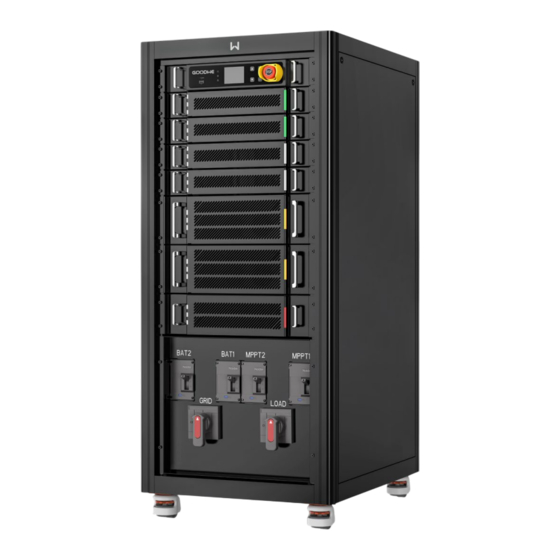
- Page 22 Emergency stop button Press the button for emergency protection. MPPT input circuit breaker • Starts or stops PV input. (MPPT1, MPPT2) • Only for ETC series. Load breaker (LOAD) Starts or stops back-up AC output. Heat sink For heat dissipation.
-
Page 23: Dimension
User Manual V1.0-2023-04-30 03 Product Introduction 3.5.2 Dimension 3.5.3 Indicator Description Indicator Status Description ON= The equipment is power on. OFF= The equipment is power off. Power ON = The system is ready. BLINK = The system is starting. Operating OFF =The system is not working. -
Page 24: Nameplate
03 Product Introduction User Manual V1.0-2023-04-30 3.5.4 Nameplate The nameplate is for reference only. GW trademark, product type, and product model Technical parameters Safety symbols and certification marks Contact information and serial number... -
Page 25: Check And Storage
04 Check and Storage User Manual V1.0-2023-04-30 4 Check and Storage 4.1 Check Before Receiving Check the following items before receiving the product. 1. Check the outer packing box for damage, such as holes, cracks, deformation, and other signs of equipment damage. Do not unpack the package and contact the supplier as soon as possible if any damage is found. -
Page 26: Storage
04 Check and Storage User Manual V1.0-2023-04-30 4.3 Storage If the equipment is not to be installed or used immediately, please ensure that the storage environment meets the following requirements: 1. Do not unpack the outer package or throw the desiccant away. 2. -
Page 27: Installation
05 Installation User Manual V1.0-2023-04-30 5 Installation 5.1 Installation Requirements Installation Environment Requirements 1. Do not install the equipment in a place near flammable, explosive, or corrosive materials. 2. Do not install the equipment in a place that is easy to touch, especially within children’s reach. High temperature exists when the equipment is working. - Page 28 05 Installation User Manual V1.0-2023-04-30 Mounting Support Requirements • The mounting support shall be nonflammable and fireproof. • Install the equipment on a surface that is solid enough to bear the inverter weight. • Do not install the product on the support with poor sound insulation to avoid the noise bothering people nearby.
-
Page 29: Inverter Installation
05 Installation User Manual V1.0-2023-04-30 Installation Tool Requirements The following tools are recommended when installing the equipment. Use other auxiliary tools on site if necessary. Safety Safety Goggles Dust mask Heat gun gloves shoes Diagonal Wire Heat shrink Vacuum Torque wrench pliers stripper tube... - Page 30 05 Installation User Manual V1.0-2023-04-30 Hoisting the inverter (optional) step 1 Install the hoisting ring to the inverter and tighten it. Step 2 Hoist the inverter. Fix the inverter Step screw the four pulleys of the inverters.
-
Page 31: Electrical Connection
06 Electrical Connection User Manual V1.0-2023-04-30 6 Electrical Connection 6.1 Safety Precaution DANGER • Perform electrical connections in compliance with local laws and regulations. Including operations, cables, and component specifications. • Disconnect the DC switch, AC output switch, and battery switch of the inverter to power off the inverter before any electrical connections. -
Page 32: System Wiring Diagram
06 Electrical Connection User Manual V1.0-2023-04-30 Single-core or multi-core outdoor copper or aluminum cable. GW50K-ETC/GW50K-BTC: • Conductor cross-sectional area (copper): 35-50 mm • Conductor cross-sectional area (aluminum): ≥50mm Load output cable (LOAD) GW100K-ETC/GW100K-BTC: • Conductor cross-sectional area (copper): 50-70 mm •... -
Page 33: Opening The Door Of The Wiring Compartment
06 Electrical Connection User Manual V1.0-2023-04-30 N and PE cables are wired separately in the main panel. The following diagram is applicable to areas except Australia, New Zealand, South Africa. • The internal relay will automatically connect the N wire and PE cable in back-up mode. -
Page 34: Connecting The Pe Cable
06 Electrical Connection User Manual V1.0-2023-04-30 NOTICE The door of the wiring compartment is not pre-drilled for the wire inlet hole. A hobby knife is required to cut a hole according to the outer diameter of the cable. Make sure that the size of the inlet hole is appropriate so that the gap is not too large, which could lead to insects, rodents or other animals entering the equipment and causing damage to the equipment. -
Page 35: Connecting Ac Output Cable, Load Output Cable, Battery Cable, And Pv Input Cable
06 Electrical Connection User Manual V1.0-2023-04-30 6.5 Connecting AC Output Cable, Load Output Cable, Battery Cable, and PV Input Cable Safety Precautions - AC Output Cable WARNING • Do not connect loads between the inverter and the AC switch directly connected to the inverter. - Page 36 06 Electrical Connection User Manual V1.0-2023-04-30 Safety Precautions - PV Input Cable NOTICE Only for hybrid inverters. DANGER • Do not connect one PV string to more than one inverter at the same time. Otherwise, it may cause damage to the inverter. •...
- Page 37 06 Electrical Connection User Manual V1.0-2023-04-30 WARNING • Connect the battery cables to the corresponding terminals such BAT1, BAT2, and grounding ports correctly. Otherwise it will cause damage to the inverter. • Ensure the DC cables are connected tightly and securely. •...
-
Page 38: Communication
06 Electrical Connection User Manual V1.0-2023-04-30 6.5 Communication NOTICE • Make sure that the communication device is connected to the right COM port. Route the communication cable far away from any interference source or power cable to prevent the signal from being influenced. •... - Page 39 06 Electrical Connection User Manual V1.0-2023-04-30 Silk- Silk- Definition Function Definition Function screen screen RS485 A I/O- DC2.485 DRY.IN10 BMS(RS485 RS485 B I/O+ communication Reserved RS485 A I/O- port) DC1.485 DRY.IN11 RS485 B I/O+ CAN H CAN H DC2.CAN BMS(CAN CAN L CAN L communication...
-
Page 40: Connecting The Communication Cable (Terminal Block)
06 Electrical Connection User Manual V1.0-2023-04-30 Inverter 6.5.1 Connecting the Communication Cable (Terminal Block) 6.5.2 Connecting the Communication Cable (RJ45 Connector) Color Orange and White Orange Green and White Blue Blue and White Green Brown and White Brown... -
Page 41: Closing The Door Of The Wiring Compartment
06 Electrical Connection User Manual V1.0-2023-04-30 Power Limit Network NOTICE Power limit can be realized when the inverter is installed with a smart meter. Utility Grid Inverter GM3000C smart Loads meter 6.6 Closing the Door of the Wiring Compartment... -
Page 42: Equipment Commissioning
All the upstream and downstream breakers are disconnected. 7.2 Power On Step 1 Turn on the AC breaker of the inverter. Step 2 Turn on the MPPT input breaker of the inverter(Only for ETC series). Step 3 Turn on the battery breaker of the inverter. -
Page 43: System Commissioning
08 System Commissioning User Manual V1.0-2023-04-30 8 System Commissioning 8.1 Indicators and Buttons Indicator Status Description ON= The equipment is power on. OFF= The equipment is power off. Power ON = The system is ready. BLINK = The system is starting. Operating OFF =The system is not working. - Page 44 08 System Commissioning User Manual V1.0-2023-04-30 Example: Set the Safety Code For Australian market, to comply with AS/NZS 4777.2:2020, please select from Australia A/B/C. please contact your local grid operator on which region to select。 Refer to the appendix for more details.
-
Page 45: Setting Inverter Parameters Via Solargo App
1. Check the operating data, software version, alarms, etc. 2. Set grid parameters, communication parameters, etc. 3. Equipment maintenance. 4. Upgrade software version. For more details, refer to SolarGo User Manual. Scan the QR code or visit https://en.goodwe. com/Ftp/EN/Downloads/User%20Manual/GW_SolarGo_User%20Manual-EN.pdf to get the user manual. SolarGo App SolarGo App User Manual 8.3 Monitoring via SEMS Portal... -
Page 46: Maintenance
• Delayed discharge. Wait until the components are discharged after power off. Step 1 Turn off the AC breaker of the inverter. Step 2 Turn off the MPPT input breaker of the inverter(Only for ETC series). Step 3 Turn off the battery breaker of the inverter. -
Page 47: Troubleshooting
09 Maintenance User Manual V1.0-2023-04-30 9.4 Troubleshooting Perform troubleshooting according to the following methods. Contact the after-sales service if these methods do not work. Collect the information below before contacting the after-sales service, so that the problems can be solved quickly. 1. - Page 48 User Manual V1.0-2023-04-30 09 Maintenance DC-AC conversion module fault Fault Cause Solutions Disconnect the AC output switch and DC The leakage input switch, then connect them 5 minutes GFCICheckFault current sensor is later. Contact the dealer or the after-sales abnormal. service if the problem persists.
- Page 49 09 Maintenance User Manual V1.0-2023-04-30 Fault Cause Solutions 1. If the problem occurs occasionally, it The input may be caused by a cable exception. insulation The inverter will recover automatically impedance GFCIFault after the problem is solved. becomes low 2. Check whether the resistance between when the inverter the PV string and PE is too low if the is working.
- Page 50 User Manual V1.0-2023-04-30 09 Maintenance Fault Cause Solutions 1. If the problem occurs occasionally, the utility grid may be abnormal temporarily. The inverter will recover automatically after detecting that the utility grid is normal. The grid voltage 2. If the problem occurs frequently, check exceeds the whether the grid voltage is within the permissible...
- Page 51 09 Maintenance User Manual V1.0-2023-04-30 Fault Cause Solutions 1. If the problem occurs occasionally, the utility grid may be abnormal temporarily. The inverter will recover DC injection is automatically after detecting that the DCIOutRange high. utility grid is normal. 2. If the problem occurs frequently, contact the dealer or the after-sales service.
- Page 52 User Manual V1.0-2023-04-30 09 Maintenance Fault Cause Solutions Disconnect the AC output switch and DC Data memory input switch, then connect them 5 minutes EepromRWFault device exception. later. Contact the dealer or the after-sales service if the problem persists. 1. Frame format error 2.
- Page 53 09 Maintenance User Manual V1.0-2023-04-30 Fault Cause Solutions The cables are Disconnect the AC output switch and DC input PhaseOrderFault connected in a switch and wait for 5 minutes. Then connect wrong phase. the phase cables in the right way. 1.
-
Page 54: Routine Maintenance
User Manual V1.0-2023-04-30 09 Maintenance Fault Cause Solutions 1. If the problem occurs occasionally, the utility grid may be abnormal temporarily. The inverter will recover automatically after detecting that the utility grid is normal. Utility grid 2. If the problem occurs frequently, check exception. -
Page 55: Technical Parameters
10 Technical Parameters User Manual V1.0-2023-04-20 10 Technical Parameters Technical Data GW100K07-ETC GW100K06-ETC GW100K05-ETC Battery Input Data Battery Type Li-Ion Li-Ion Li-Ion Nominal Battery Voltage 422.4 / 499.2 / 576 422.4 / 499.2 / 576 / 422.4 / 499.2 / 576 / / 652.8 652.8 652.8... - Page 56 10 Technical Parameters User Manual V1.0-2023-04-20 Nominal Output Voltage (V) 400,3L/N/PE 400,3L/N/PE 400,3L/N/PE 312~460(AU); 312~460(AU); 312~460(AU); Output Voltage Range (V) 318~497(Germany) 318~497(Germany) 318~497(Germany) Nominal AC Grid Frequency 50/60 50/60 50/60 (Hz) AC Grid Frequency Range 47~52(AU); 47~52(AU); 47~52(AU); (Hz) 47.5~51.5(Germany) 47.5~51.5(Germany) 47.5~51.5(Germany) Max.
- Page 57 10 Technical Parameters User Manual V1.0-2023-04-20 PV Insulation Resistance Integrated Integrated Integrated Detection Residual Current Integrated Integrated Integrated Monitoring PV Reverse Polarity Integrated Integrated Integrated Protection Battery Reverse Polarity Integrated Integrated Integrated Protection Anti-islanding Protection Integrated Integrated Integrated AC Overcurrent Protection Integrated Integrated Integrated...
- Page 58 10 Technical Parameters User Manual V1.0-2023-04-20 AC Connector OT/DT terminal (Max. 70mm²) Environmental Category 3K3H Pollution Degree Overvoltage Category DC II / AC III Protective Class Storage Temperature (℃) -30~+60 Battery: C The Decisive Voltage Class PV: C (DVC) AC: C Com: A Mounting Method Grounded...
- Page 59 10 Technical Parameters User Manual V1.0-2023-04-20 Max. Apparent Power from Utility Grid (kVA) Nominal Output Voltage 400,3L/N/PE 400,3L/N/PE 400,3L/N/PE 312~460(AU); 312~460(AU); 312~460(AU); Output Voltage Range (V) 318~497(Germany) 318~497(Germany) 318~497(Germany) Nominal AC Grid 50/60 50/60 50/60 Frequency (Hz) AC Grid Frequency Range 47~52(AU);...
- Page 60 10 Technical Parameters User Manual V1.0-2023-04-20 European Efficiency 97.3% 97.3% 97.3% Max. Battery to AC 97.2% 97.2% 97.2% Efficiency Protection Residual Current Integrated Integrated Integrated Monitoring Battery Reverse Polarity Integrated Integrated Integrated Protection Anti-islanding Protection Integrated Integrated Integrated AC Overcurrent Protection Integrated Integrated Integrated...
- Page 61 10 Technical Parameters User Manual V1.0-2023-04-20 AC Connector OT/DT terminal (Max. 70mm²) Environmental Category 3K3H Pollution Degree Overvoltage Category DC II / AC III Protective Class Storage Temperature (℃) -30~+60 Battery: C The Decisive Voltage Class PV: C (DVC) AC: C Com: A Mounting Method Grounded...
- Page 62 10 Technical Parameters User Manual V1.0-2023-04-20 Nominal Input Voltage (V) Max. Input Current per MPPT (A) Max. Short Circuit Current per MPPT (A) Max. Backfeed Current to The Array (A) Number of MPP Trackers AC Output Data (On-grid) Nominal Apparent Power Output to Utility Grid (kVA) Max.
- Page 63 10 Technical Parameters User Manual V1.0-2023-04-20 Max. Output Apparent Power (kVA) Nominal Output Current (A) 72.5 72.5 Max. Output Current (A) 79.8 79.8 Nominal Output Voltage (V) Nominal Output Freqency 50/60 50/60 (Hz) Output THDv (@Linear <3% <3% Load) Efficiency Max.
- Page 64 10 Technical Parameters User Manual V1.0-2023-04-20 Operating Temperature -20~+60(>45℃ derating) Range (℃) 0~95% (Non-condensing) Relative Humidity Max. Operating Altitude (m) 4000 Cooling Method Smart Fan Cooling User Interface LED, LCD , WLAN+APP Communication with BMS CAN, RS485 Communication with Meter RS485 Communication with Portal RS485, LAN/Bluetooth...
- Page 65 10 Technical Parameters User Manual V1.0-2023-04-20 Technical Data GW50K07-BTC GW50K06-BTC GW50K05-BTC Battery Input Data Battery Type Li-Ion Li-Ion Li-Ion Nominal Battery Voltage 422.4 / 499.2 / 576 422.4 / 499.2 / 576 / 422.4 / 499.2 / 576 / / 652.8 652.8 652.8 Battery Voltage Range (V)
- Page 66 10 Technical Parameters User Manual V1.0-2023-04-20 Max. Total Harmonic <3% <3% <3% Distortion Type of Voltage (a.c. or d.c.) a.c. a.c. a.c. AC Output Data (Back-up) Back-up Nominal Apparent Power (kVA) Max. Output Apparent Power (kVA) Nominal Output Current (A) 72.5 72.5 Max.
- Page 67 Mounting Method Grounded Active Anti-islanding AFDPF + AQDPF Method Type of Electrical Supply TN-S, TN-C, TN-C-S, TT, IT System Country of Manufacture China *1: Nominal Battery Voltage (V): With GOODWE battery model: LXC101-10: 422.4V, LXC120-10: 499.2V, LXC138-10: 576V, LXC156-10: 652.8V...
-
Page 68: Appendix
11 Appendix... - Page 69 Official Website GoodWe Technologies Co.,Ltd. No. 90 Zijin Rd., New District, Suzhou, 215011, China www.goodwe.com service@goodwe.com Local Contacts...
Need help?
Do you have a question about the ETC Series and is the answer not in the manual?
Questions and answers