Goodwe ET Series User Manual
Hybrid inverter
Hide thumbs
Also See for ET Series:
- User manual ,
- Quick installation manual (37 pages) ,
- Connection manual (3 pages)
Table of Contents
Advertisement
Advertisement
Table of Contents

Related Manuals for Goodwe ET Series


Summary of Contents for Goodwe ET Series
- Page 1 User Manual Hybrid Inverter ET Series V1.0-2021-06-15...
-
Page 2: Table Of Contents
Content User Manual V1.0-2021-06-15 TABLE OF CONTENTS 01 Introduction .............. 1 1.1 Operation Modes Introduction ..............1 1.2 Safety and Warning ...................2 1.3 Product Overview ..................4 02 Installation Instructions ..........5 2.1 Unacceptable Installations ...............5 2.2 Packing List ....................6 2.3 Mounting ....................6 2.3.1 Select Mounting Location ................. - Page 3 User Manual V1.0-2021-06-15 Content 04 OTHER ..............30 4.1 Error Messages..................30 4.2 Troubleshooting ..................32 4.3 Disclaimer ....................36 4.4 Technical Parameters ................38 4.5 Quick Checklist To Avoid Dangerous Conditions .........46 Appendix ..............47...
-
Page 4: Introduction
User Manual V1.0-2021-06-15 01 Introduction The ET series, also called hybrid or bidirectional solar inverters, provides energy management in a PV system that includes solar modules, a battery, loads, and utility grid connection. Energy produced by the PV system is prioritized to supply loads and then any excess energy to charge the battery. -
Page 5: Safety And Warning
01 Introduction 1.2 Safety and Warning The ET series of inverters from Jiangsu Goodwe Power Supply Technology Co.,Ltd (also called GoodWe) strictly complies with related safety rules for product design and testing. Please read and follow all of the instructions and cautions appearing on the inverter or in the User Manual during installation, operation and maintenance, as any improper operation might cause personal injury or property damage. - Page 6 01 Introduction User Manual V1.0-2021-06-15 Safety Warnings Any installation or operations on the inverter must be performed by qualified electricians in compliance with standards, wiring rules and the requirements of local grid authorities or companies (such as AS 4777 and AS/NZS 3000 in Australia). Never insert or remove the AC or DC connections when the inverter is running.
-
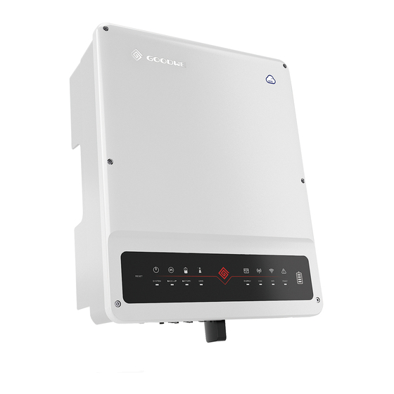
Page 7: Product Overview
User Manual V1.0-2021-06-15 01 Introduction 1.3 Product Overview 6 7 8 PV Input Terminal DC Switch Battery Terminal(BAT+/BAT-) (PV+/PV-) Communication Module Port (WiFi or COM Terminal METER Communication Port Bluetooth) BMS Communication AC Terminal (ON- WiFi Reset Port GRID and BACKUP) Indicator PE Terminal 12. -
Page 8: Installation Instructions
01 Introduction User Manual V1.0-2021-06-15 LED Indicators EXPLANATION INDICATOR STATUS COLOR ON = System is ready BLINK = System is starting up OFF = System is not operating SYSTEM ON = Back-up is ready / power available OFF = Back-up is off / on power available BACK-UP ON = Battery is charging BLINK 1 = Battery is discharging... -
Page 9: Packing List
User Manual V1.0-2021-06-15 02 Installation Instructions Smart Meter Battery Backup Load The Inverter does not support off-grid One meter cannot be connected One battery bank cannot be functions in gridless areas. to multiple inverters. Different CTs connected to multiple inverters. cannot connect to the same line cable. -
Page 10: Mounting
02 Installation Instructions User Manual V1.0-2021-06-15 Rule 4. Ambient temperature should be lower than 45°C (113°F). High ambient temperature will cause power derating of inverter. The temperature and humidity at the installation site should be within the appropriate range (60 °C for outdoor unconditioned with solar effects). Rule 5. - Page 11 User Manual V1.0-2021-06-15 02 Installation Instructions The inverter is suitable for mounting on concrete or other non-combustible surfaces only. Please use the mounting bracket as a template to drill 4 holes in the correct positions (e.g. 10mm in diameter and 80mm in depth). Use the expansion bolts in the accessory box and tightly attach the mounting bracket to the wall.
-
Page 12: Electrical Wiring Connection
02 Installation Instructions User Manual V1.0-2021-06-15 The inverters can be locked for anti-theft purposes if this is necessary for individual requirements. 1.2~2N·m The lock is not included in the package and can be purchased by the user. 2.4 Electrical Wiring Connection 2.4.1 PE Cable Connection L=L1+(1~2)mm 1.2~2N·m... -
Page 13: Pv Wiring Connection
Make sure the battery is under normal working condition (such as battery voltage and BMS setting etc.) when the inverter and battery is to be used. If you need to use the hybrid inverter as a Grid-tied inverter, please contact GoodWe after-sales. - Page 14 02 Installation Instructions User Manual V1.0-2021-06-15 Make sure that the battery switch is off and that the nominal battery voltage meets ET series specifications before connecting the battery to the inverter. Make sure the inverter is totally isolated from both PV and AC power. Please strictly follow the requirements and steps listed below.
-
Page 15: On-Grid&Back-Up Connection
02 Installation Instructions User Manual V1.0-2021-06-15 2.4.4 On-Grid&Back-up Connection An external AC breaker is needed for on-grid connection to isolate the inverter from the utility grid when necessary. Note: Backup function is optional for the German market, even though the hardware connector is always there. - Page 16 User Manual V1.0-2021-06-15 02 Installation Instructions Place the AC cable through the terminal cover as shown in the figure. Note: Please use the terminals in the accessory box. Screw Cap The Insulator Single Hole AC Sheet Cover Cables Seal Ring Press the connectors tightly on the cable conductor core.
- Page 17 Declarations for the backup function The backup outputs of the ET hybrid inverters have overload capability. For details please refer to the technical parameters in the ET series inverter section (Page 35). The inverter has self-protection derating at high ambient temperatures.
-
Page 18: Communication Connections
ET inverter via RS485 communications, and limit the power exportation. GM3000 or SEC1000S are suggested. For more detailed information of the Smart Meter, refer to the Smart Meter user manual in https://en.goodwe.com. Note: 1. The Smart Meter with CT is already configured ; please do not change any settings on the Smart Meter. -
Page 19: Bms Connection
02 Installation Instructions User Manual V1.0-2021-06-15 Position Color Smart Function Meter Function Orange & white 485_A2 485_A Orange 485_B Green & white 485_B2 485_B1 485_A Blue CAN_H Blue & white CAN_L Green 485_A1 485_B Brown & white 485_B1 Brown 485_A1 Smart Meter LED indications STATUS Blinking... -
Page 20: Com Terminal Connection
User Manual V1.0-2021-06-15 02 Installation Instructions ONLY 2.5.3 COM Terminal Connection Follow the pin definition below to connect the communication cables. Do not remove the resistor or short circuit wire unless you are going to use the corresponding PINs. Definition Function Definition Function... - Page 21 02 Installation Instructions User Manual V1.0-2021-06-15 Prepare the communication cable and remove the plug of the communication terminal. 6~8mm 0.12~0.8mm Dismantle the communication module and take out the pin terminal. To avoid water and dust, keep the rubber plug to seal the unused holes.
-
Page 22: Earth Fault Alarm Connection
2.6 Earth Fault Alarm Connection ET series inverters comply with IEC 62109-2 13.9. The fault indicator LED on the inverter cover will light up and the system will email the fault information to customer. It must be installed in a... - Page 23 02 Installation Instructions User Manual V1.0-2021-06-15 Wiring system for the ET series hybrid inverter Note: This diagram indicates the wiring structure of the ET series hybrid inverter, not the electric wiring standard. To Battery AC Breaker AC Breaker...
- Page 24 User Manual V1.0-2021-06-15 02 Installation Instructions If the inverter is not equipped with a DC switch, an external DC breaker shall be added. The external DC breaker shall be AU/NZ certified; Complied to AS60947.3:2018; Be classified as DC-PV 2; With ratings and properties suitable for the intended application conditions such as outdoor, exposed to sunshine, on non-combustible material surface.
- Page 25 02 Installation Instructions User Manual V1.0-2021-06-15 When the inverter is working in backup mode, neutral and PE on the backup side are connected via the internal relay. Also, this internal relay will be open when the inverter is working in grid-tied mode. Distribution box Backup Loads...
-
Page 26: Manual Operation
User Manual V1.0-2021-06-15 03 MANUAL OPERATION 03 MANUAL OPERATION 3.1 Wi-Fi Configuration This part shows the configuration using a web page. Wi-Fi configuration is absolutely necessary for online monitoring and maintenance. Preparation: 1. The inverter must be powered up with battery or grid power. 2. -
Page 27: Pv Master
Operation steps are the same for Android system and iOS system although the two interfaces are slightly different. For more detailed opertaion instructions, please refer to PV Master user manual in www.goodwe.com. PV Master App Note: For Australian customers please select from Australia Region A/B/C to comply with AS/NZS 4777.2:2020. -
Page 28: Load Control
User Manual V1.0-2021-06-15 03 MANUAL OPERATION Log in using the initial password for the first time and change the password as soon as possible. To ensure account security, you are advised to change the password periodically and keep the new password in mind. Steps to connect the WiFi: Step 1: PV Master →Connect Device→Inverter with WiFi Step 2: Phone Settings→WLAN→Solar-WiFi********... - Page 29 03 MANUAL OPERATION User Manual V1.0-2021-06-15 • Select Power Switch Mode and tap OFF. Once the inverter receives OFF command, the contactor will be disconnected and loads be powered off. AC Breaker DO port Contactor DO Relay Inverter Power Switch Mode -OFF (Three-Phase Load) Load Time Mode...
- Page 30 User Manual V1.0-2021-06-15 03 MANUAL OPERATION Note: • The intelligent mode cannot be set when the inverter is working in off-grid mode. • Switch off Export Power Limit before setting intelligent mode. • Load consumption time means the shortest load working time after the loads been turned on. The time is set to prevent the loads be turned on and off frequently when the PV power fluctuates greatly.
-
Page 31: Battery Ready And Force Charge To Battery
03 MANUAL OPERATION User Manual V1.0-2021-06-15 AC Breaker DO port SOC<60% Contactor DO Relay Inverter BACKUP Load Control-OFF (Three-Phase Load) Load 3.2.3 Battery Ready and Force Charge to Battery Battery Ready(ETR) Battery Ready function is a fee-based function, which is off by default. Contact the after-sales service to pay for the function and obtain the series number. -
Page 32: Cei Auto-Test Function
User Manual V1.0-2021-06-15 03 MANUAL OPERATION Force Charge to Battery Tap Advanced Setting→Battery Setting →Force Charge to Battery→SOC(discontinue)→Save to set the SOC and start force charge to battery function. After starting the force battery to charge function, the power of the system gives priority to charging the battery until the preset SOC is reached. -
Page 33: Other
04 OTHER User Manual V1.0-2021-06-15 04 OTHER 4.1 Error Messages. The error messages below will be displayed on PV Master App or reported by e-mail if an error occurs. ERROR EXPLANATION REASON SOLUTIONS MESSAGE Utility Phase The sequence of The inverter has The L2 and L3 cables are connected Failure the on-grid wire is... - Page 34 User Manual V1.0-2021-06-15 04 OTHER PV/BAT The PV or BAT The total voltage 1. Check if the PV string Voc is lower Overvoltage voltage is too (open-circuit than the Max PV input voltage of the high voltage) of each inverter. If the Voc of the PV string is PV string high, please decrease the number of is higher than...
-
Page 35: Troubleshooting
04 OTHER User Manual V1.0-2021-06-15 Neutral & ground Check (use multi-meter) if there is cables are not high voltage (normally should be connected well on lower than 10V) between N & PE Relay Check Self checking of AC side or just an cable on the AC side. - Page 36 User Manual V1.0-2021-06-15 04 OTHER Grid House Click Loads Figure 4.2-1 Figure 4.2-2 Figure 4.2-3 Figure 4.2-4 Checks At Startup And Turning On AC Power Battery settings, BMS communication and safety country setting: After connecting the Solar-Wi-Fi* (*The Wi-Fi signal is named as the last 8 characters of the inverter's serial number.).
- Page 37 04 OTHER User Manual V1.0-2021-06-15 2. Make sure the load power is greater than 150W. a. The battery will not discharge continuously unless the load power is greater than 150W. b. If the battery does not discharge when the Meter power is greater than 150W, please check the Smart Meter &...
- Page 38 Q: Which battery should I use for the ET? A: For the ET series inverter, it can connect to lithium batteries which have compatibility with ET-series inverters with nominal voltages from 180 V to 600 V. For compatible lithium batteries, please refer to the battery list in the PV Master App.
-
Page 39: Disclaimer
A: AFDPF(Active Frequency Drift with Positive Feedback) + AQDPF(Active Q Drift with Positive Feedback) 4.3 Disclaimer The ET series inverters are transported, used and operated under environmental and electrical conditions. The manufacturer has the right to not provide after-sales services or assistance under the following conditions: •... - Page 40 • Any incompatible batteries, loads or other devices are connected to the ET system. • Specifications are subject to change without notice. Every effort has been made to make this document complete, accurate and up-to-date. However, GoodWe may need to make some improvements under certain circumstances without advance notice. GoodWe shall not be responsible for any loss caused by this document including, but not limited omissions errors,typographical errors, arithmetical errors or listing errors in this document.
-
Page 41: Technical Parameters
04 OTHER User Manual V1.0-2021-06-15 4.4 Technical Parameters Technical Data GW5KL-ET GW6KL-ET GW8KL-ET GW10KL-ET Battery Input Data Battery Type Li-Ion Nominal battery voltage (V) Battery Voltage Range (V) 180~600 Max. Charging Current (A) Max. Discharging Current (A) Max charge power (W) 7500 7800 9600... - Page 42 User Manual V1.0-2021-06-15 04 OTHER Output Voltage Range (V) 0~300 Nominal Output Freqency (Hz) 50/60 AC Grid Frequency Range (Hz) 45~65 Nominal Output Current (A) 12.0 14.5 Max. AC Current Output to Utility Grid 10.5 13.5 16.5 Max. AC Current From Utility Grid (A) 15.2 18.2 22.7...
- Page 43 04 OTHER User Manual V1.0-2021-06-15 Protection DC Insulation Resistance Detection Integrated Residual Current Monitoring Unit Integrated Anti-islanding Protection AFDPF + AQDPF *5 DC Reverse Polarity Protection Integrated AC Overcurrent Protection Integrated AC Short Circuit Protection Integrated AC Overvoltage Protection Integrated DC Surge Arrester Type III AC Surge Arrester...
- Page 44 User Manual V1.0-2021-06-15 04 OTHER Environmental Category 4K4H Storage environments(℃) -40~+85 Pollution Degree Overvoltage Category DCII / AC III Battery: C PV: C The Decisive Voltage Class (DVC) AC: C Com: A Mounting method Wall Bracket Type of electrical supply system Three phase Grid Certifications &...
- Page 45 User Manual V1.0-2021-06-15 04 OTHER Technical Data GW5K-ET GW6.5K-ET GW8K-ET GW10K-ET Battery Input Data Battery Type Li-Ion Nominal battery voltage (V) Battery Voltage Range (V) 180~600 Max. Charging Current (A) Max. Discharging Current (A) Max charge power (W) 7500 7800 9600 10000 Max discharge power (W)
- Page 46 04 OTHER User Manual V1.0-2021-06-15 Output Voltage Range (V) 0~300 Nominal Output Freqency (Hz) 50/60 AC Grid Frequency Range (Hz) 45~65 Nominal Output Current (A) 12.0 14.5 Max. AC Current Output to Utility Grid 10.5 13.5 16.5 Max. AC Current From Utility Grid (A) 15.2 18.2 22.7...
- Page 47 User Manual V1.0-2021-06-15 04 OTHER DC Insulation Resistance Detection Integrated Residual Current Monitoring Unit Integrated Anti-islanding Protection AFDPF + AQDPF *5 DC Reverse Polarity Protection Integrated AC Overcurrent Protection Integrated AC Short Circuit Protection Integrated AC Overvoltage Protection Integrated DC Surge Arrester Type II AC Surge Arrester Type III...
- Page 48 User Manual V1.0-2021-06-15 04 OTHER Pollution Degree Overvoltage Category DCII / AC III Battery: C PV: C The Decisive Voltage Class (DVC) AC: C com: A Mounting method Wall Bracket Type of electrical supply system Three phase Grid Certifications & Standards*8 VDE-AR-N 4105;...
-
Page 49: Quick Checklist To Avoid Dangerous Conditions
04 OTHER User Manual V1.0-2021-06-15 4.5 Quick Checklist To Avoid Dangerous Conditions 1. The inverter must not be installed near flammable or explosive materials or near equipment with strong electromagnetic fields. Please refer to page 6. 2. Remember that this inverter is heavy! Please be careful when lifting from the package. Please refer to page 7. -
Page 50: Appendix
User Manual V1.0-2021-06-15 Appendix Appendix Protection category definition Moisture location category definition Level Moisture Parameters 4K4H Temperature Range 0~+40°C -33~+40°C ~20~+55°C Moisture Parameters 5%~85% 15%~100% 4%~100% Environment category definition Environment Condition Ambient Temperature Relative Humidity Applied to Outdoor -20~50°C 4%~100% Indoor Unconditioned -20~50°C 5%~95%... - Page 51 01 Introduction User Manual V1.0-2021-06-15 Pollution degree definition No pollution or only dry, non-conductive polllution occurs. The Pollution Degree I pollution has no influence. Normally only non-conductive pollution occurs. Occasionally, however, Pollution Degree II a temporary conductivity caused by condensation must be expected. Conductive pollution occurs, or dry.
- Page 52 Jiangsu Goodwe Power Supply Technology Co.,Ltd No. 90 Zijin Rd., New District, Suzhou, 215011, China www.goodwe.com service@goodwe.com Local Contacts...
Need help?
Do you have a question about the ET Series and is the answer not in the manual?
Questions and answers