Goodwe ET Series User Manual
Hybrid inverter 5.0-10.0kw ac-coupled inverter 5.0-10.0kw
Hide thumbs
Also See for ET Series:
- User manual ,
- Quick installation manual (37 pages) ,
- Connection manual (3 pages)

Related Manuals for Goodwe ET Series


Summary of Contents for Goodwe ET Series
- Page 1 User Manual Hybrid Inverter ET Series / ET Plus Series 5.0-10.0kW AC-Coupled Inverter BT Series 5.0-10.0kW V1.1-2022-12-20...
- Page 2 User Manual V1.1-2022-12-20 COPYRIGHT Trademarks and other GoodWe trademarks are trademarks of GoodWe Technologies Co.,Ltd. All other trademarks or registered trademarks mentioned in this manual are owned by the company. NOTICE The information in this user manual is subject to change due to product updates or other reasons.
-
Page 3: Table Of Contents
CONTENT User Manual V1.1-2022-12-20 CONTENT 1 About This Manual ���������������������������������������������������������������������������� 1 1.1 Applicable Model ........................1 1.2 Target Audience ........................1 1.3 Symbol Definition ........................2 1.4 Updates ............................2 2 Safety Precaution ����������������������������������������������������������������������������� 3 2.1 General Safety ...........................3 2.2 PV String Safety ........................3 2.3 Inverter Safety ..........................4 2.4 Battery Safety ...........................5 2.5 Personnel Requirements ......................5... - Page 4 User Manual V1.1-2022-12-20 CONTENT 6.4 Connecting the DC Input Cable (PV) ..................31 6.5 Connecting the Battery Cable ....................34 6.6 Connecting the AC Cable ....................... 36 6.7 Communication ........................39 6.7.1 Connecting the Communication Cable ....................39 6.7.2 Connecting the Meter Communication Cable ..................43 6.7.3 Connecting the BMS Communication Cable ..................
-
Page 5: About This Manual
All the installers and users have to be familiar with the product features, functions, and safety precautions. This manual is subject to update without notice. For more product details and latest documents, visit https://en.goodwe.com. 1.1 Applicable Model... -
Page 6: Symbol Definition
01 About This Manual User Manual V1.1-2022-12-20 1.3 Symbol Definition Different levels of warning messages in this manual are defined as follows: DANGER Indicates a high-level hazard that, if not avoided, will result in death or serious injury. WARNING Indicates a medium-level hazard that, if not avoided, could result in death or serious injury. CAUTION Indicates a low-level hazard that, if not avoided, could result in minor or moderate injury. -
Page 7: Safety Precaution
The manufacturer shall not be liable for equipment damage or personal injury if you do not follow the instructions. For more warranty details, please visit https:// en.goodwe.com/warranty. 2.2 PV String Safety DANGER Connect the DC cables using the delivered DC connectors and terminals.The manufacturer shall not be liable for the equipment damage if other connectors or terminals are used. -
Page 8: Inverter Safety
02 Safety Precaution User Manual V1.1-2022-12-20 2.3 Inverter Safety WARNING • The voltage and frequency at the connection point should meet the inverter grid connection requirements. • Additional protective devices like circuit breakers or fuses are recommended on the AC side. -
Page 9: Battery Safety
User Manual V1.1-2022-12-20 02 Safety Precaution 2.4 Battery Safety WARNING • The battery used with the inverter shall be approved by the inverter manufacturer. The approved battery list can be obtained through the official website. • Before installations, read through the corresponding battery's User Manual to learn about the product and the precautions. -
Page 10: Eu Declaration Of Conformity
02 Safety Precaution User Manual V1.1-2022-12-20 2.6 EU Declaration of Conformity GoodWe Technologies Co., Ltd. hereby declares that the inverter with wireless communication modules sold in the European market meets the requirements of the following directives: • Radio Equipment Directive 2014/53/EU (RED) •... -
Page 11: Product Introduction
• 8K: the rated power is 8kW. • 10K: the rated power is 10kW. Product Feature • L: lower voltage • N: higher PV input current Series Code • ET: ET series hybrid inverter • BT: BT series AC-Coupled inverter... -
Page 12: Application Scenarios
03 Product Introduction User Manual V1.1-2022-12-20 Supported Grid Types For the grid type with neutral wire, the voltage between the neutral wire and the ground must be less than 10V. TN-S TN-C TN-C-S Inverter Inverter Inverter Inverter 3.2 Application Scenarios WARNING •... - Page 13 User Manual V1.1-2022-12-20 03 Product Introduction Self Consumption System (Hybrid Scenarios) Smart meter AC circuit breaker Inverter Utility Utility grid meter AC circuit PV string breaker Battery breaker Household loads Battery SPDT (Single Pole, Double Throw) switch BACK-UP loads Parts Description PV string PV string is composed of series connected PV panels.
- Page 14 • Before enabling the power limit function, ensure that the AC-Coupled inverter or hybrid inverter supports power limit. • Enable the power limit function if GoodWe AC-Coupled inverter or grid-tied PV inverter is applied in the PV system. Complete the power limit settings as required if a grid-tied PV inverter from other manufacturers is applied.
-
Page 15: Working Mode
Included in the deliverables of the inverter. Recommended model: (for AC-Coupled GM3000. Inverter) Smart meter • When a GoodWe inverter is applied, GM3000 is recommended. (for Grid-Tied PV • When the inverter is from other manufacturer, model of the Inverter) smart meter depends on the inverter. - Page 16 03 Product Introduction User Manual V1.1-2022-12-20 Self consumption mode NOTICE • For solar power, consider self consumption mode in priority: the excess power charges the battery in day time; the battery supplies power to the load when there is no solar power generated at night.
- Page 17 User Manual V1.1-2022-12-20 03 Product Introduction Back-up mode NOTICE • The back-up mode is mainly applied to the scenario where the grid is unstable and there is an important load. When the grid is disconnected, the inverter turns to off-grid mode to supply power to the load;...
-
Page 18: Inverter Operation Mode
03 Product Introduction User Manual V1.1-2022-12-20 3.3.2 Inverter operation mode Off-grid mode Waiting mode Self-check mode Grid-Tied mode Fault mode Parts Description Waiting Waiting stage after the inverter is powered on. mode • When the conditions are met, it enters the self-check mode. •... -
Page 19: Features
User Manual V1.1-2022-12-20 03 Product Introduction 3.4 Features Power derating For a safe operation, the inverter will automatically reduce the output power when the operating environment is not ideal. The following are the factors that may occur power derating. Please try to avoid them when the inverter is working. - Page 20 03 Product Introduction User Manual V1.1-2022-12-20 Communication Communication module like Bluetooth, 4G, WiFi, and LAN is supported. The inverter supports parameter setting in a short distance. Connecting to the server via 4G, WiFi, or LAN to monitor the working status of the inverter and the running situations of the power plant, etc.
-
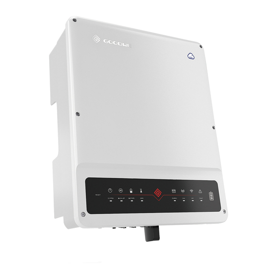
Page 21: Appearance
Starts or stops DC input. Only for hybrid inverters. GW5KL-ET, GW6KL-ET, GW8KL-ET,GW10KL-ET: optional. PV input terminal Connects the PV module DC input cables. Only for ET series and ET Plus series. Battery input Connects the battery input cables. terminal Communication... -
Page 22: Dimension
03 Product Introduction User Manual V1.1-2022-12-20 3.5.2 Dimension 180mm 415mm 120mm 110mm 3.5.3 Indicator Description Indicator Status Description ON = The system is ready. BLINK = The system is starting. SYSTEM OFF =The system is not working. ON = Back-up is ready / power available. BACK-UP OFF = Back-up is off / power not available. -
Page 23: Nameplate
P.F. : ~1,0.8cap...0.8ind, Operating: -35~60℃ Non-isolated, IP66, protective Class I, OVC DCII/ACIII Safety symbols and certification marks Contact information and serial number Good We Technologie s Co. , Ltd. E-mail:service@goodwe.co No.90 Zijin Rd., New District , Suzhou , 21501 1, China... -
Page 24: Check And Storage
04 Check and Storage User Manual V1.1-2022-12-20 4 Check and Storage 4.1 Check Before Receiving Check the following items before receiving the product. 1. Check the outer packing box for damage, such as holes, cracks, deformation, and other signs of equipment damage. Do not unpack the contents from the box and contact the supplier as soon as possible if any damage is found. -
Page 25: Storage
User Manual V1.1-2022-12-20 04 Check and Storage Mounting plate OT terminal Expansion Inverter x 1 PV connectors x N bolts x N Battery Communication Smart Meter Screw x N AC connector x N connectors x N terminal x 1 Documents Communication Bluetooth AC connector x 1... -
Page 26: Installation
05 Installation User Manual V1.1-2022-12-20 5 Installation 5.1 Installation Requirements Installation Environment Requirements 1. Do not install the equipment in a place near flammable, explosive, or corrosive materials. 2. Do not install the equipment in a place that is easy to touch, especially within children’s reach. High temperature exists when the equipment is working. - Page 27 User Manual V1.1-2022-12-20 05 Installation ALT: 4000m IP66 0%~95%RH Mounting Support Requirements • The mounting support shall be nonflammable and fireproof. • Install the equipment on a surface that is solid enough to bear the inverter weight. • Do not install the product on the support with poor sound insulation to avoid the noise bothering people nearby.
- Page 28 05 Installation User Manual V1.1-2022-12-20 Installation Tool Requirements The following tools are recommended when installing the equipment. Use other auxiliary tools on site if necessary. RJ45 Goggles Safety shoes Safety gloves Dust mask crimping tool Diagonal pliers Wire stripper Hammer drill Heat gun Vacuum cleaner M3/M5...
-
Page 29: Inverter Installation
User Manual V1.1-2022-12-20 05 Installation 5.2 Inverter Installation 5.2.1 Moving the Inverter CAUTION • Operations such as transportation, shipment, installation and so on shall in compliance with laws and regulations of the country or region where the inverter is located. •... - Page 30 05 Installation User Manual V1.1-2022-12-20 1.2~2N·m...
-
Page 31: Electrical Connection
User Manual V1.1-2022-12-20 06 Electrical Connection 6 Electrical Connection 6.1 Safety Precaution DANGER • Perform electrical connections in compliance with local laws and regulations. Including operations, cables, and component specifications. • Disconnect the DC switch and the AC output switch of the inverter to power off the inverter before any electrical connections. -
Page 32: System Wiring Diagram
06 Electrical Connection User Manual V1.1-2022-12-20 6.2 System Wiring Diagram NOTICE N and PE wiring via ON-GRID and BACK-UP ports of the inverter are different based on the regulation requirements of different regions. Refer to the specific requirements of local regulations. - Page 33 User Manual V1.1-2022-12-20 06 Electrical Connection N and PE cables shall be wired separately in the Main Panel. The following diagram is applicable to areas except Australia, New Zealand, South Africa. • The internal relay will automatically connect the N wire and PE cable when the inverter is in BACK-UP mode.
-
Page 34: Connecting The Pe Cable
06 Electrical Connection User Manual V1.1-2022-12-20 6.3 Connecting the PE Cable WARNING • The PE cable connected to the enclosure of the inverter cannot replace the PE cable connected to the AC output port. Make sure that both of the two PE cables are securely connected. -
Page 35: Connecting The Dc Input Cable (Pv)
User Manual V1.1-2022-12-20 06 Electrical Connection 6.4 Connecting the DC Input Cable (PV) NOTICE Only for hybrid inverters. DANGER • Do not connect one PV string to more than one inverter at the same time. Otherwise, it may cause damage to the inverter. •... - Page 36 06 Electrical Connection User Manual V1.1-2022-12-20 Stäubli MC4 PV connector 7 - 8mm Φ: 4-5mm 7 - 8mm ≤S≤6mm Click Click ≤1000V...
- Page 37 User Manual V1.1-2022-12-20 06 Electrical Connection Vaconn PV connector 2.5mm ≤S≤4mm Click Click ≤1000V...
-
Page 38: Connecting The Battery Cable
06 Electrical Connection User Manual V1.1-2022-12-20 6.5 Connecting the Battery Cable DANGER • The battery used with the inverter shall be approved by the inverter manufacturer. The approved battery list can be obtained through the official website. • A short circuit in the battery may cause personal injury. The instantaneous high current caused by a short circuit can release a large amount of energy and may cause a fire. - Page 39 User Manual V1.1-2022-12-20 06 Electrical Connection 15mm Φ: 5.5-8mm 15mm Φ: 5.5-8mm ≤S≤6mm...
-
Page 40: Connecting The Ac Cable
06 Electrical Connection User Manual V1.1-2022-12-20 6.6 Connecting the AC Cable WARNING • Do not connect loads between the inverter and the AC switch directly connected to the inverter. • An AC circuit breaker should be installed on the AC side to make sure that the inverter can safely disconnect the grid when an exception happens. - Page 41 User Manual V1.1-2022-12-20 06 Electrical Connection WARNING • Pay attention to the L1, L2, L3, N and PE terminals. Connect the AC cables to the corresponding terminals. The inverter may be damaged if the cables are connected to the wrong terminal. •...
- Page 42 06 Electrical Connection User Manual V1.1-2022-12-20 Type II 7-9mm 20-25mm Φ: 13-18mm Copper, 4mm ≤S≤6mm...
-
Page 43: Communication
User Manual V1.1-2022-12-20 06 Electrical Connection 6.7 Communication NOTICE Make sure that the communication device is connected to the right COM port. Route the communication cable far away from any interference source or power cable to prevent the signal from being influenced. 6.7.1 Connecting the Communication Cable Type I (18PIN Terminal Block) Definition... - Page 44 06 Electrical Connection User Manual V1.1-2022-12-20 NOTICE • Do not remove the resistor or short circuit wire unless you are going to use DRED or RCR. • Enable the DRED function or remote shutdown function via SolarGo app after cable connections.
- Page 45 User Manual V1.1-2022-12-20 06 Electrical Connection DRED or RCR 1.5N·m Remote Shutdown 1.5N·m...
- Page 46 06 Electrical Connection User Manual V1.1-2022-12-20 Type II (6PIN Terminal Block) 6~8mm 25mm 1: DRM 1/5 DRED 2: DRM2/6 3: DRM3/7 4: DRM4/8 5: REFGEN 6: COM/DRMO 0.8N·m Remote 5: REFGEN 6: COM/DRMO Shutdown 0.8N·m Enable the DRED function or remote shutdown function via SolarGo app after cable connections.
-
Page 47: Connecting The Meter Communication Cable
User Manual V1.1-2022-12-20 06 Electrical Connection 6.7.2 Connecting the Meter Communication Cable NOTICE • The smart meter and CT have been preset parameters before delivered with the inverter. Do not modify the relevant parameters. • Each smart meter needs to be connected to one inverter independently. Do not connect one smart meter to multiple inverters. -
Page 48: Connecting The Bms Communication Cable
06 Electrical Connection User Manual V1.1-2022-12-20 Smart Meter Network ≤100m Smart meter Power meter Utility grid Inverter 6.7.3 Connecting the BMS Communication Cable NOTICE • CAN communication is the default communication method between the inverter and the battery. Contact the after-sales service for RS485 communication cable if you prefer RS485 communication. -
Page 49: Connecting The Ems Communication Cable
User Manual V1.1-2022-12-20 06 Electrical Connection Color Orange 485_A2 and White Orange Green and 485_B2 White To Battery Blue CAN_H Blue and CAN_L White Green Brown and White Brown 6.7.4 Connecting the EMS Communication Cable NOTICE Connect the EMS communication cable to the 18PIN communication terminal block when a 18PIN terminal block is applied. -
Page 50: Installing The Communication Module (Optional)
4G module. Set inverter parameters, check running information and fault information, and observe system status in time via the smartphone or web pages. NOTICE Refer to the delivered communication module user manual to get more introduction to the module. For more detailed information, visit www.goodwe.com. -
Page 51: Equipment Commissioning
User Manual V1.1-2022-12-20 07 Equipment Commissioning 7 Equipment Commissioning Check Item 7.1 Check Before Power ON The product is firmly installed at a clean place that is well-ventilated and easy-to operate. The PE cable, DC input cable, AC output cable, and communication cable are connected correctly and securely. -
Page 52: System Commissioning
08 System Commissioning User Manual V1.1-2022-12-20 8 System Commissioning 8.1 Indicators and Buttons Indicator Status Description ON = The system is ready. SYSTEM BLINK = The system is starting. OFF =The system is not working. ON = Back-up is ready / power available. BACK-UP OFF = Back-up is off / power not available. -
Page 53: Setting Inverter Parameters Via Solargo App
1. Check the operating data, software version, alarms, etc. 2. Set grid parameters, communication parameters, etc. 3. Equipment maintenance. 4. Upgrade software version. For more details, refer to SolarGo User Manual. Scan the QR code or visit https://en.goodwe. com/Ftp/EN/Downloads/User%20Manual/GW_SolarGo_User%20Manual-EN.pdf to get the user manual. SolarGo App SolarGo App User Manual 8.3 Monitoring via SEMS Portal... -
Page 54: Maintenance
09 Maintenance User Manual V1.1-2022-12-20 9 Maintenance 9.1 Power OFF the Inverter DANGER INSTRUCTIONS PERTAINING TO A RISK OF FIRE OR ELECTRIC SHOCK. • Power off the inverter before operations and maintenance. Otherwise, the inverter may be damaged or electric shocks may occur. •... -
Page 55: Troubleshooting
09 Maintenance User Manual V1.1-2022-12-20 9.4 Troubleshooting Perform troubleshooting according to the following methods. Contact the after-sales service if these methods do not work. Collect the information below before contacting the after-sales service, so that the problems can be solved quickly. 1. - Page 56 09 Maintenance User Manual V1.1-2022-12-20 Fault Cause Solutions 1. If the problem occurs occasionally, the utility grid may be abnormal temporarily. The inverter will recover automatically after detecting that the utility grid is normal. 2. Check whether the high grid voltage continues for a long time.
- Page 57 09 Maintenance User Manual V1.1-2022-12-20 Fault Cause Solutions 1. If the problem occurs occasionally, the utility grid may be abnormal temporarily. The inverter will recover automatically after detecting that the utility grid is normal. The moving 2. If the problem occurs frequently, check average of grid whether the grid voltage is within the Grid 10min...
- Page 58 09 Maintenance User Manual V1.1-2022-12-20 Fault Cause Solutions 1. If the problem occurs occasionally, the utility grid may be abnormal temporarily. The inverter will recover automatically after detecting that the utility grid is normal. 2. If the problem occurs frequently, check Utility grid whether the grid frequency is within the exception.
- Page 59 09 Maintenance User Manual V1.1-2022-12-20 Fault Cause Solutions The utility grid is disconnected. The utility grid 1. Check whether the utility grid is is disconnected disconnected. Anti-islanding according to the 2. Contact the dealer or the after-sales safety regulations, service. but the grid voltage is maintained due to the loads.
- Page 60 09 Maintenance User Manual V1.1-2022-12-20 Fault Cause Solutions 1. Check whether the resistance of the PV string to PE exceeds 50kΩ. If no, check the short circuit point. 2. Check whether the PE cable is connected 1. The PV string is correctly.
- Page 61 09 Maintenance User Manual V1.1-2022-12-20 Fault Cause Solutions 1. Frame format error 2. Parity checking error 3. Can bus offline Disconnect the AC output switch and DC 4. Hardware CRC Internal Comm input switch, then connect them 5 minutes error Loss later.
- Page 62 09 Maintenance User Manual V1.1-2022-12-20 Fault Cause Solutions 1. The DC terminal is not firmly Read the Quick Installation Guide and check DC Arc Fault connected. whether the cables are connected properly. 2. The DC cable is broken. Disconnect the AC output switch and DC AFCI Self-test AFCI detection is input switch, then connect them 5 minutes...
- Page 63 09 Maintenance User Manual V1.1-2022-12-20 Fault Cause Solutions 1. The PV Disconnect the AC output switch and DC PV Continuous configuration is input switch, then connect them 5 minutes Software not proper. later. Contact the dealer or the after-sales Overcurrent 2.
-
Page 64: Routine Maintenance
09 Maintenance User Manual V1.1-2022-12-20 9.5 Routine Maintenance Maintaining Item Maintaining Method Maintaining Period Check the heat sink, air intake, and air System Clean Once 6-12 months outlet for foreign matter or dust. Turn the DC switch on and off ten DC Switch consecutive times to make sure that it is Once a year... -
Page 65: Technical Parameters
User Manual V1.1-2022-12-20 10 Technical Parameters 10 Technical Parameters 10.1 Technical Parameters - ET/ET Plus Series Technical Parameters GW5KL-ET GW6KL-ET GW8KL-ET GW10KL-ET Battery Input Data Battery Type Li-Ion Li-Ion Li-Ion Li-Ion Nominal Battery Voltage (V) Battery Voltage Range (V) 180 ~ 600 180 ~ 600 180 ~ 600 180 ~ 600... - Page 66 10 Technical Parameters User Manual V1.1-2022-12-20 Technical Parameters GW5KL-ET GW6KL-ET GW8KL-ET GW10KL-ET 400/380, 400/380, 400/380, 400/380, Nominal Output Voltage (V) 3L/N/PE 3L/N/PE 3L/N/PE 3L/N/PE Nominal AC Grid Frequency (Hz) 50/60 50/60 50/60 50/60 Max. AC Current Output to Utility 10.5 13.5 16.5 Grid (A)
- Page 67 User Manual V1.1-2022-12-20 10 Technical Parameters Technical Parameters GW5KL-ET GW6KL-ET GW8KL-ET GW10KL-ET General Data Operating Temperature Range (℃) -35 ~ +60 -35 ~ +60 -35 ~ +60 -35 ~ +60 Relative Humidity 0~95% 0~95% 0~95% 0~95% Max. Operating Altitude (m) 4000 4000 4000...
- Page 68 10 Technical Parameters User Manual V1.1-2022-12-20 Technical Parameters GW5KL-ET GW6KL-ET GW8KL-ET GW10KL-ET *1: For 1000V system: Maximum operating voltage is 950V. *2: According to the local grid regulation. *3: Can be reached only if PV and battery power is enough. *4: CAN communication is configured default.
- Page 69 User Manual V1.1-2022-12-20 10 Technical Parameters Technical Parameters GW5K-ET GW6.5K-ET GW8K-ET GW10K-ET Battery Input Data Battery Type Li-Ion Li-Ion Li-Ion Li-Ion Nominal Battery Voltage (V) Battery Voltage Range (V) 180 ~ 600 180 ~ 600 180 ~ 600 180 ~ 600 Max.
- Page 70 10 Technical Parameters User Manual V1.1-2022-12-20 Technical Parameters GW5K-ET GW6.5K-ET GW8K-ET GW10K-ET Nominal AC Grid Frequency (Hz) 50/60 50/60 50/60 50/60 Max. AC Current Output to Utility 10.8 13.5 16.5 Grid (A) Max. AC Current From Utility Grid (A) 15.2 19.7 22.7 22.7...
- Page 71 User Manual V1.1-2022-12-20 10 Technical Parameters Technical Parameters GW5K-ET GW6.5K-ET GW8K-ET GW10K-ET Operating Temperature Range (℃) -35 ~ +60 -35 ~ +60 -35 ~ +60 -35 ~ +60 Relative Humidity 0~95% 0~95% 0~95% 0~95% Max. Operating Altitude (m) 4000 4000 4000 4000 Cooling Method...
- Page 72 10 Technical Parameters User Manual V1.1-2022-12-20 Technical Parameters GW5K-ET GW6.5K-ET GW8K-ET GW10K-ET *1: For 1000V system: Maximum operating voltage is 950V. *2: According to the local grid regulation. *3: Can be reached only if PV and battery power is enough. *4: For Belgium Max.
- Page 73 User Manual V1.1-2022-12-20 10 Technical Parameters Technical Parameters GW5KN-ET GW6.5KN-ET GW8KN-ET GW10KN-ET Battery Input Data Battery Type Li-Ion Li-Ion Li-Ion Li-Ion Nominal Battery Voltage (V) Battery Voltage Range (V) 180 ~ 600 180 ~ 600 180 ~ 600 180 ~ 600 Max.
- Page 74 10 Technical Parameters User Manual V1.1-2022-12-20 Technical Parameters GW5KN-ET GW6.5KN-ET GW8KN-ET GW10KN-ET Nominal AC Grid Frequency (Hz) 50/60 50/60 50/60 50/60 Max. AC Current Output to Utility 10.8 13.5 16.5 Grid (A) Max. AC Current From Utility Grid (A) 15.2 19.7 22.7 22.7...
- Page 75 User Manual V1.1-2022-12-20 10 Technical Parameters Technical Parameters GW5KN-ET GW6.5KN-ET GW8KN-ET GW10KN-ET Operating Temperature Range (℃) -35 ~ +60 -35 ~ +60 -35 ~ +60 -35 ~ +60 Relative Humidity 0~95% 0~95% 0~95% 0~95% Max. Operating Altitude (m) 4000 4000 4000 4000 Cooling Method...
- Page 76 10 Technical Parameters User Manual V1.1-2022-12-20 Technical Parameters GW5KN-ET GW6.5KN-ET GW8KN-ET GW10KN-ET *1: For 1000V system: Maximum operating voltage is 950V. *2: According to the local grid regulation. *3: Can be reached only if PV and battery power is enough. *4: For Belgium Max.
-
Page 77: Technical Parameter - Bt Series
User Manual V1.1-2022-12-20 10 Technical Parameters 10.2 Technical Parameter - BT Series Technical Parameters GW5K-BT GW6K-BT GW8K-BT GW10K-BT Battery Input Data Battery Type Li-Ion Li-Ion Li-Ion Li-Ion Nominal Battery Voltage (V) Battery Voltage Range (V) 180 ~ 600 180 ~ 600 180 ~ 600 180 ~ 600 Max. - Page 78 10 Technical Parameters User Manual V1.1-2022-12-20 Technical Parameters GW5K-BT GW6K-BT GW8K-BT GW10K-BT Nominal Output Voltage (V) 400/380 400/380 400/380 400/380 Nominal Output Frequency (Hz) 50/60 50/60 50/60 50/60 Output THDv (@Linear Load) <3% <3% <3% <3% Efficiency Max. Efficiency 97.60% 97.60% 97.60% 97.60%...
- Page 79 User Manual V1.1-2022-12-20 10 Technical Parameters Technical Parameters GW5K-BT GW6K-BT GW8K-BT GW10K-BT Ingress Protection Rating IP66 IP66 IP66 IP66 DC Connector MC4 (4~6mm AC Connector Feed-Through Terminal Blocks UW10 Environmental Category 4K4H 4K4H 4K4H 4K4H Pollution Degree Overvoltage Category DC II/AC III DC II/AC III DC II/AC III DC II/AC III...
- Page 80 Official Website GoodWe Technologies Co.,Ltd. No. 90 Zijin Rd., New District, Suzhou, 215011, China www.goodwe.com service@goodwe.com Contact Information...
Need help?
Do you have a question about the ET Series and is the answer not in the manual?
Questions and answers