Goodwe BTC Series User Manual
Hide thumbs
Also See for BTC Series:
- Quick installation manual (154 pages) ,
- User manual (69 pages) ,
- Quick installation manual (17 pages)
Table of Contents
Advertisement
Quick Links
Advertisement
Table of Contents

Subscribe to Our Youtube Channel
Related Manuals for Goodwe BTC Series


Summary of Contents for Goodwe BTC Series
- Page 1 BTC Series User Manual Ver 1.0 2021-01-15...
-
Page 2: Table Of Contents
TABLE OF CONTENTS 01 INTRODUCTION ..............1 1.1 Operation Modes Introduction ................1 1.2 Safety & Warning....................2 1.3 Product Overview ....................4 INSTALLATION INSTRUCTIONS ..........5 2.1 Select Mounting Location ..................5 2.2 Mounting ......................6 2.3 Electrical Wiring Connection ................7 2.3.1 System connection diagrams ..................7 2.3.2 System Application ....................... -
Page 3: Introduction
01 INTRODUCTION GoodWe BTC series bidirectional inverter is designed for indoor use, which could be used with or without existing grid-tied inverter systems to store energy using batteries. Energy produced from the grid-tied inverters will be used to optimize self-consumption, excess will be used to charge the battery, anymore could be exported to the grid. -
Page 4: Safety & Warning
1.2 Safety & Warning The BTC series inverter of Jiangsu GoodWe Power Supply Technology Co., Ltd. (hereinafter called as GoodWe) strictly complies with related safety rules for product design and testing. Please read and follow all the instructions and cautions on the inverter or user manual during installation, operation or maintenance, as any improper operation might cause personal or property damage. - Page 5 Safety warning Any installation and operation on inverter must be performed by qualified electricians, in compliance with standards, wiring rules or requirements of local grid authorities or companies (like AS 4777 and AS/NZS 3000 in Australia). Prohibit inserting and pulling the AC and DC terminals when the inverter is running. Before any wiring connection or electrical operation on inverter, all DC and AC power must be disconnected from inverter for at least 5 minutes to make sure inverter is totally isolated to avoid electric shock.
-
Page 6: Product Overview
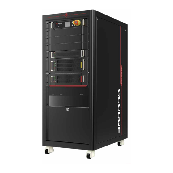
1.3 Product Overview The BTC series inverter is a battery energy storage inverter that can be used for grid-connected, emergency power supply, hybrid power supply and other distributed power generation systems. This document focuses on the product model: GW50K-BTC GW50K-BTC... -
Page 7: Installation Instructions
Dimension Requirements Front Side 585 mm 750 mm Bottom 60 mm 36 mm 107 mm INSTALLATION INSTRUCTIONS 2.1 Select Mounting Location For inverter's protection and convenient maintenance, mounting location for inverter should be selected carefully based on the following rules: Any part of this system shouldn't block the switch and breaker from disconnecting the inverter from DC and AC power. -
Page 8: Mounting
2.2 Mounting Inverter cannot be installed near flammable, explosive or strong electro-magnetic equipment. The inverter is suitable for mounting on concrete or other non-combustible surface only. Cabinet Lifting Fixed Cabinet... -
Page 9: Electrical Wiring Connection
2.3 Electrical Wiring Connection 2.3.1 System connection diagrams Note: According to Australian safety regulation, the neutral cable of on-grid side and back-up side must be connected together, otherwise back-up function will not work. This diagram is an example for application that Neutral connects together with PE in distribution box. -
Page 10: System Application
2.3.2 System Application 1 2 3 4 5 6 7 8 SEMS Router RJ45 Modular GM3000C Plug Inverter Main Meter RS485 Grid LOAD S1 S2 External CT AC Circuit Breaker Load Key Load Battery Cables Type Specification Protective Earth (PE) Single-conductor outdoor copper wire (PE: M8 OT terminal) Cross-sectional area of conductor: 16 mm2 - 25 mm2 AC output line(GRID) -
Page 11: Electrical Wiring Connection
2.3.3 Electrical Wiring Connection Opening the Wiring Chamber Door • Before connecting AC, DC and communication cables, connect the ground terminals to the protective ground point to ensure reliable grounding of the inverter. • Please be careful about any electric shock or chemical hazard. •... - Page 12 Protective Earth Wiring 7 - 9 N¤M L + (2 - 3 mm) Connecting the AC Output Line, Load Output Line and DC Power Line Port Description Notes GRID Connects to the AC output line L1/L2/L3/N/PE: M8 screws, Tightening torque: 7 - 9 N·M LOAD Connects to the load output line BATTERY...
- Page 13 Communication Line Connections • The wiring methods for connecting communication lines through the terminal block are the same, and this document uses the RS485_1 port connection as an example to illustrate the procedures. • The DRY_OUT, CAN_2, RS485_3, DRY_IN1, DRY_IN2, DRY_IN3 and DRY_ IN4 ports are reserved.
- Page 14 Wiring method for RJ45 terminals Colour Orange and White 1 2 3 4 5 6 7 8 Orange Green and White Blue Blue and White Green Brown and White Brown Special adjustable setting The inverter has a field where the user could set functions, such as trip points, trip time, time of reconnection, active and invalid of QU curve and PU curve.
- Page 15 Accepted loads as below: • Inductive load: The maximum starting power of the load should be less than the inverter power. • Capacitive load: Total power <= 0.6 x nominal power of model. (Any load with high startup current at start-up is not accepted.) •...
-
Page 16: Earth Fault Alarm Connection
4. When using anti-reverse function, it would buy about 500W from the grid. 2.4 Earth Fault Alarm Connection BTC series inverter complies with IEC 62109-2 13.9. Fault indicator LED on the inverter cover will light up and the system will email the fault information to customer. -
Page 17: Checks Before System Power-Up
Checks Before System Power-up Checklist Verify that the inverter is securely installed. Verify that the protective ground wires, power lines and communication lines are connected in the correct and secure order. Verify that the cable straps meet the wiring requirements and are well distributed, and ensure the straps are fastened without any sharp corners after cutting. -
Page 18: Parameter Setup
After the inverter is powered on, the LCD screen of the monitoring unit automatically turns on and enters the home page. • Access to the settings page requires a password, please contact GOODWE Service Center to obtain the password. 1. Press Enter on the homepage to access the main menu page. -
Page 19: Others
Others 6 .1 Error Messages The error messages below will be displayed on PV Master App or reported by e-mail if the error occurs. ERROR EXPLANATION REASON SOLUTIONS MESSAGE Utility Phase The sequence of Inverter detects Reverse connection order of L2 and L3 cable. Failure on-grid wire is that phase angle... - Page 20 Isolation Ground insulation Isolation failure 1. Use multi meter to check if the resistance Failure impedance of could be caused between earth & inverter frame is about zero. If Battery is to low by multiple it's not, please ensure that the connection is well. reasons like 2.
- Page 21 Problems During Operation BTC does not start up with only battery Solution: Make sure the voltage of battery is higher than 250V, otherwise battery cannot start BTC up. High power fluctuation on battery charge or discharge: Solution: Check if there is a fluctuation on load power. Battery does not charge: Solution: Make sure BMS communication is OK on the LCD screen.
- Page 22 100% follow the instructions, please contact after-sales. 4.3 Disclaimer The BTC series inverters are transported, used and operated under environmental and electrical conditions. Manufacturer has the right not to provide after-sales services or assistance under following conditions: •...
-
Page 23: Technical Parameters
6.2 Technical Parameters Technical Data GW50K-BTC Battery Input Dat Battery Voltage Range (V) 200~865 Start-up Voltage (V) No. of Battery Input Max Discharge/Charge Current (A) Charging Mode for Battery Self-adaption to BMS DC breaker Integrated AC Output Data (Ongrid mode) Nominal Output Power (VA) Max. - Page 24 Protection Reverse Protection Integrated Anti-islanding Protection Integrated Insulation Resistor Detection Integrated Residual Current Monitoring Unit Integrated AC SPD Protection Integrated Output Over Current Protection Integrated Output Short Protection Integrated Output Over Voltage Protection Integrated General Data Operating Temperature Range (℃) -25~60 Relative Humidity 0~95%...
-
Page 25: Other Test
6.3 Other Test For Australian requirements, in the THDi test, Zref should be added between inverter and mains. RA, XA for Line conduvtor RN, XN for Neutral conductor Zref: RA=0, 24; XA=j0,15 at 50Hz; RN=0, 16; XN=j0,10 at 50Hz 6.4 Quick Check List To Avoid Danger Inverter cannot be installed near flammable, explosive or strong electro-magnetic equipment, please refer to page 06 Remember that this inverter is heavy! Please be careful when lifting out from the package,... - Page 26 Moisture location category definition Level Moisture Parameters 4K4H ~20~+55℃ Temperature Range 0~+40℃ -33~+40℃ Moisture Parameters 5%~85% 15%~100% 4%~100% Environment category definition Environment Ambient Termperature Relative Humidity Applied to Condition Outdoor -20~50℃ 4%~100% Indoor Unconditioned -20~50℃ 5%~95% Indoor conditioned 0~40℃ 5%~85% Pollution degree definition No pollution or only dry, non-conductive polllution occurs.
- Page 27 9050KBTC 20A 80001 50.00kW Status: Normal Communicate info Safety Code: 50Hz Grid Network: 70.00kW Settings Server: Load tcp.goodwe.power.com Maintenance down down 2020/11/20 16 :00:00 2020/11/20 16 :00:00 2020/11/20 16 :00:00 2020/11/20 16 :00:00 2020/11/20 16 :00:00 Long press Short press short press...
- Page 28 PV Master APP SEMS Portal APP SEMS Portal website LinkedIn Company's www.semsportal.com offical website JIANGSU GOODWE POWER SUPPLY TECHNOLOGY CO.,LTD No. 90 Zijin Rd., New District, Suzhou, 215011, China www.goodwe.com service@goodwe.com...
Need help?
Do you have a question about the BTC Series and is the answer not in the manual?
Questions and answers