Goodwe GW15K-ET User Manual
Hybrid inverter 15-30kw
Hide thumbs
Also See for GW15K-ET:
- User manual (163 pages) ,
- Quick manual (9 pages) ,
- Quick installation manual (18 pages)
Table of Contents
Advertisement
Quick Links
Advertisement
Table of Contents

Related Manuals for Goodwe GW15K-ET


Summary of Contents for Goodwe GW15K-ET
- Page 1 User Manual Hybrid Inverter ET Series 15-30kW V1.6-2024-03-20...
- Page 2 Copyright©GoodWe Technologies Co., Ltd. All rights reserved. No part of this manual can be reproduced or transmitted to the public platform in any form or by any means without the prior written authorization of GoodWe Technologies Co.,Ltd. Trademarks and other GOODWE trademarks are trademarks of GoodWe Technologies Co.,Ltd.
-
Page 3: Table Of Contents
CONTENT User Manual V1.6-2024-03-20 CONTENT 1 About This Manual ���������������������������������������������������������������������������� 1 1.1 Applicable Model ........................1 1.2 Target Audience ........................1 1.3 Symbol Definition ........................1 2 Safety Precaution ����������������������������������������������������������������������������� 2 2.1 General Safety ..........................2 2.2 PV String Safety ........................2 2.3 Inverter Safety ..........................3 2.4 Battery Safety ...........................4 2.5 Personnel Requirements ......................4 2.6 EU Declaration of Conformity ....................4... - Page 4 User Manual V1.6-2024-03-20 CONTENT 6.5 Connecting the Battery Cable ....................36 6.6 Connecting the AC Cable ....................... 41 6.7 Communication Connection ....................43 6.7.1 Connecting the Communication Cable ....................44 6.7.2 Connecting the BMS or Meter Communication Cable ................46 6.7.3 Installing the Communication Module (Optional) ................
-
Page 5: About This Manual
All the installers and users have to be familiar with the product features, functions, and safety precautions. This manual is subject to update without notice. For more product details and latest documents, visit https://en.goodwe.com. 1.1 Applicable Model... -
Page 6: Safety Precaution
• Strictly follow the installation, operation, and configuration instructions in this manual. The manufacturer shall not be liable for equipment damage or personal injury if you do not follow the instructions. For more warranty details, please visit https://en.goodwe.com/ warranty. 2.2 PV String Safety DANGER Connect the DC cables of the inverter to the included DC terminals. -
Page 7: Inverter Safety
User Manual V1.6-2024-03-20 02 Safety Precaution 2.3 Inverter Safety WARNING • The voltage and frequency at the connecting point should meet the on-grid requirements. • Additional protective devices like circuit breakers or fuses are recommended on the AC side. Specification of the protective device should be at least 1.25 times the maximum AC output current. -
Page 8: Battery Safety
2.6 EU Declaration of Conformity GoodWe Technologies Co., Ltd. hereby declares that the inverter with wireless communication modules sold in the European market meets the requirements of the following directives: • Radio Equipment Directive 2014/53/EU (RED) •... -
Page 9: Product Introduction
The power generated in the PV system can be used, stored in the battery, output to the utility grid, etc. Model This manual applies to the listed inverters below: • GW15K-ET • GW20K-ET • GW25K-ET • GW29.9K-ET • GW30K-ET... -
Page 10: Application Scenarios
03 Product Introduction User Manual V1.6-2024-03-20 3.2 Application Scenarios WARNING • The PV system is not suitable to connect equipment that relies on a stable power supply, such as medical equipment to sustain life. Ensure that no personal injury is occurred when the system is disconnected. - Page 11 Depend on the actual using load. breaker ON-GRID Self-prepared breaker. Recommended specifications: breaker • GW15K-ET: nominal current≥32A, nominal voltage≥400V • GW20K-ET: nominal current≥40A, nominal voltage≥400V • GW25K-ET: nominal current≥50A, nominal voltage≥400V • GW29.9K/30K-ET: nominal current≥63A, nominal voltage≥400V Smart meter The smart meter is delivered with the inverter or purchased from the...
- Page 12 • Do not connect auto-coupling or isolation transformers. BACK-UP load Self-prepared breaker. Recommended specifications: breaker • GW15K-ET: nominal current≥32A, nominal voltage≥400V • GW20K-ET: nominal current≥40A, nominal voltage≥400V • GW25K-ET: nominal current≥50A, nominal voltage≥400V • GW29.9K/30K-ET: nominal current≥63A, nominal voltage≥400V Bypass switch To ensure the BACK-UP load is powered by the grid during the inverter maintenance, install a bypass switch by yourself.
- Page 13 • the firmware versions of all inverters are consistent, andthe DSP version is above 07 and the ARM version is above 08. • firmware version of EzLink is above 04. • If the firmware version does not meet the requirements, please contact GoodWe to upgrade the software version.
- Page 14 03 Product Introduction User Manual V1.6-2024-03-20 RS485 ON-GRID ON-GRID breaker Master PV string inverter BACK-UP Bypass Battery 1 Smart Battery Ezlink switch Meter breaker BACK-UP load breaker Ensure correct location and direction of CT. BACK-UP load ON-GRID Slave PV string inverter 1 Power ON-GRID breaker...
- Page 15 The AC breakers should be prepared by customers. Recommended specifications: • GW15K-ET: nominal current ≥32A, nominal voltage ≥400V • GW20K-ET: nominal current ≥ 40A, nominal voltage ≥ 400V • GW25K-ET: nominal current ≥50A, nominal voltage ≥400V • GW29.9K-ET, GW30K-ET: nominal current ≥ 63A, nominal voltage ≥...
- Page 16 UP load specifications: breaker • GW15K-ET: nominal current ≥32A, nominal voltage ≥400V • GW20K-ET: nominal current ≥ 40A, nominal voltage ≥ 400V • GW25K-ET: nominal current ≥50A, nominal voltage ≥400V • GW29.9K-ET, GW30K-ET: nominal current ≥ 63A, nominal voltage ≥...
-
Page 17: Working Mode
03 Product Introduction User Manual V1.6-2024-03-20 3.3 Working Mode 3.3.1 System Working Mode Self Consumption Mode NOTICE • For solar power, consider self consumption mode in priority: the excess power charges the battery in day time; the battery supplies power to the load when there is no solar power generated at night. - Page 18 03 Product Introduction User Manual V1.6-2024-03-20 Economic Mode NOTICE • Economic mode can only be selected if local laws and regulations are met, such as whether to allow the power grid to charge the battery and whether to allow the battery to be discharged and sold to the power grid.
- Page 19 03 Product Introduction User Manual V1.6-2024-03-20 Delayed Charging Mode NOTICE • Delayed charging mode can prevent the battery from quickly filling up and wasting energy when the PV energy exceeds the limit power value. • It applies to regions with grid connected power output limitations. •...
- Page 20 03 Product Introduction User Manual V1.6-2024-03-20 Peak Shaving mode NOTICE Peak Shaving mode is mainly applicable to industrial and commercial scenarios. When the total power consumption of the load exceeds the power consumption quota in a short period of time, battery discharge can be used to reduce the power exceeding the quota. •...
-
Page 21: Inverter Operation Mode
03 Product Introduction User Manual V1.6-2024-03-20 3.3.2 Inverter Operation Mode Waiting mode Off-grid mode Self-check mode Fault mode Grid-Tied mode Parts Description Waiting Waiting stage after the inverter is powered on or clearing the alarms. • When the conditions are met, it enters self-check mode. mode •... -
Page 22: Features
24 hours. The inverter cannot work normally until the fault is solved. Please refer to the SolarGo App User Manual for detailed operations. Model Label Description F: Full coverage GW15K-ET I: Integrated AFPE: Detection and interruption capability provided F-I-AFPE-1-2/2-2 1: 1 monitored string per input port GW20K-ET... - Page 23 03 Product Introduction User Manual V1.6-2024-03-20 Load Control The inverter reserves a dry contact controlling port, which supports connecting additional contactors to enable/disable the loads, such as household loads, heat pumps, etc. The load control methods are as follows: • Time control: set the time to enable/disable the loads, and the loads will be turned on or off automatically within the setting time period.
-
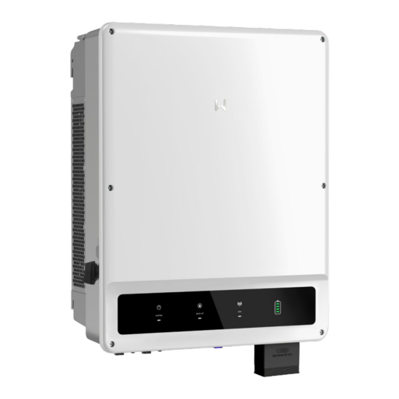
Page 24: Appearance
03 Product Introduction User Manual V1.6-2024-03-20 3.5 Appearance 3.5.1 Parts 4 5 6 PV input terminal DC switch lock hole DC switch (PV+/-) Communication METER communication Communication port module port (COM) port (COM2) Battery input terminal AC output terminal BMS communication port (BAT+/-) (On-Grid and Back-Up) Indicators... -
Page 25: Indicators
03 Product Introduction User Manual V1.6-2024-03-20 3.5.3 Indicators Inverter SOC indicator Indicator Status Description The inverter is powered on and in standby mode. The inverter is starting and in self-check mode. The inverter is in normal operation under grid-tied or off-grid modes. -
Page 26: Nameplate
Safety symbols and certification marks Contact information and serial number Good We Tec hno lo gi es Co., Ltd. E-ma il :s ervi ce @goodwe .c om No.90 Ziji n Rd., New Dis tric t, S uz hou , 2150 11, Chin a... -
Page 27: Check And Storage
04 Check and Storage User Manual V1.6-2024-03-20 4 Check and Storage 4.1 Check Before Receiving Check the following items before receiving the product. 1. Check the outer packing box for damage, such as holes, cracks, deformation, and other signs of equipment damage. Do not unpack the package and contact the supplier as soon as possible if any damage is found. - Page 28 04 Check and Storage User Manual V1.6-2024-03-20 Inverter *1 Mounting plate *1 PV connector *N PV tool *1 Battery tool *1 Battery connector *N 7PIN terminal *1 6PIN terminal *1 3PIN terminal *1 PE screw *1 L1 L2 Insulation board Expansion OT terminal *12 AC cover *1...
-
Page 29: Storage
04 Check and Storage User Manual V1.6-2024-03-20 4.3 Storage If the equipment is not to be installed or used immediately, please ensure that the storage environment meets the following requirements: 1. Do not unpack the outer package or throw the desiccant away. 2. -
Page 30: Installation
05 Installation User Manual V1.6-2024-03-20 5 Installation 5.1 Installation Requirements Installation Environment Requirements 1. Do not install the equipment in a place near flammable, explosive, or corrosive materials. 2. Do not install the equipment in a place that is easy to touch, especially within children’s reach. High temperature exists when the equipment is working. - Page 31 User Manual V1.6-2024-03-20 05 Installation IP66 ALT: 4000m 0%~95%RH Mounting Support Requirements • The mounting support shall be nonflammable and fireproof. • Install the equipment on a surface that is solid enough to bear the inverter weight. • Do not install the product on the support with poor sound insulation to avoid the noise generated by the working product, which may annoy the residents nearby.
- Page 32 05 Installation User Manual V1.6-2024-03-20 Installation Tool Requirements The following tools are recommended when installing the equipment. Use other auxiliary tools on site if necessary. RJ45 crimping Goggles Safety shoes Safety gloves Dust mask tool Diagonal pliers Wire stripper Hammer drill Heat gun Vacuum cleaner M5/M6...
-
Page 33: Inverter Installation
User Manual V1.6-2024-03-20 05 Installation 5.2 Inverter Installation 5.2.1 Moving the Inverter CAUTION • Operations such as transportation, turnover, installation and so on must meet the requirements of the laws and regulations of the country or region where it is located. •... - Page 34 05 Installation User Manual V1.6-2024-03-20 D:80mm φ:8mm With handles Only for Australia. Without handles 1.2~2N·m Only for Australia.
-
Page 35: Electrical Connection
06 Electrical Connection User Manual V1.6-2024-03-20 6 Electrical Connection 6.1 System Wiring Diagram NOTICE • N and PE wiring via ON-GRID and BACK-UP ports of the inverter are different based on the regulation requirements of different regions. Refer to the specific requirements of local regulations. - Page 36 06 Electrical Connection User Manual V1.6-2024-03-20 N and PE cables are separately wired in the Main Panel. NOTICE • Ensure that the grounding of BACK-UP is correctly and tightened. Otherwise, the BACK-UP function may be abnormal in case of grid failure. •...
-
Page 37: Safety Precaution
06 Electrical Connection User Manual V1.6-2024-03-20 6.2 Safety Precaution DANGER • Perform electrical connections in compliance with local laws and regulations. Including operations, cables, and component specifications. • Disconnect the DC switch and the AC output switch of the inverter to power off the inverter before any electrical connections. -
Page 38: Connecting The Dc Input Cable(Pv)
06 Electrical Connection User Manual V1.6-2024-03-20 L=L1+2mm Copper, 4mm ≤S≤6mm 1.2~2N·m 6.4 Connecting the DC Input Cable(PV) DANGER • Do not connect one PV string to more than one inverter at the same time. Otherwise, it may cause damage to the inverter. •... - Page 39 06 Electrical Connection User Manual V1.6-2024-03-20 7-8mm Φ: 4-5mm 7-8mm Copper, 4mm ≤S≤6mm Click Click ≤1000V...
-
Page 40: Connecting The Battery Cable
06 Electrical Connection User Manual V1.6-2024-03-20 6.5 Connecting the Battery Cable DANGER • The battery used with the inverter shall be approved by the inverter manufacturer. The approved battery list can be obtained through the official website. • A short circuit in the battery may cause personal injury. The instantaneous high current caused by a short circuit can release a large amount of energy and may cause a fire. - Page 41 06 Electrical Connection User Manual V1.6-2024-03-20 GW15K-ET or GW20K-ET can be connected to only one battery system. The battery cable must be connected to the BAT1+/- ports, as shown below. BAT1+ BAT1- COM2 COM1 COM3 BMS1 Battery system GW25K-ET, GW29.9K-ET, and GW30K-ET can be connected to one or two battery systems, as shown below.
- Page 42 06 Electrical Connection User Manual V1.6-2024-03-20 When connecting a single battery system to BAT2+/- ports of the inverter, the BMS communication cable should be connected to the BMS2 port as below. BAT2+ BAT2- COM2 COM1 COM3 BMS2 Battery system When the nominal charge and discharge current of the single battery system is higher than 50A, the single battery system can be connected to BAT1+/- and BAT2+/- ports of the inverter.
- Page 43 06 Electrical Connection User Manual V1.6-2024-03-20 When connecting two single battery systems to BAT2+/- ports of the inverter, the BMS communication cable should be connected to the BMS1 or BMS2 port respectively as below. COM2 COM1 COM3 BAT1+ BAT1- BMS1 Battery system 1 BAT2+ BAT2-...
- Page 44 06 Electrical Connection User Manual V1.6-2024-03-20 7-8mm Φ: 6.5-8.5mm 7-8mm Copper, 10mm Click Click...
-
Page 45: Connecting The Ac Cable
06 Electrical Connection User Manual V1.6-2024-03-20 6.6 Connecting the AC Cable WARNING • Do not connect loads between the inverter and the AC switch directly connected to the inverter. • The residual current monitoring unit (RCMU) is integrated into the inverter to avoid the residual current exceeds the limit. - Page 46 06 Electrical Connection User Manual V1.6-2024-03-20 11-13mm 70-80mm Φ: 21-26mm Copper, 10mm ≤S≤16mm 2-3N·m 2-3N·m 3-4N·m...
-
Page 47: Communication Connection
06 Electrical Connection User Manual V1.6-2024-03-20 6.7 Communication Connection NOTICE • Make sure that the communication device is connected to the right COM port. Route the communication cable far away from any interference source or power cable to prevent the signal from being influenced. -
Page 48: Connecting The Communication Cable
06 Electrical Connection User Manual V1.6-2024-03-20 Optionnal function. Supplies power for Power supply external devices. 12V_S Controls the RSD Reserved. Connects to RSD_12V and 12V_S to RSD_12V modules externally. control the RSD module rapidly. Remote shutdown/ Optionnal function. Controls the equipment Remote NS Protection on/off remotely. - Page 49 06 Electrical Connection User Manual V1.6-2024-03-20 NOTICE • To ensure waterproof protection, do not remove the waterproof seal of the unused ports. • RJ45 connector with the following definition can be connected: 6-8mm 45mm Φ: 6mm 0.2mm ≤S≤0.3mm EMS/PAR EMS/PAR Dry Contact Color EMS/PAR...
-
Page 50: Connecting The Bms Or Meter Communication Cable
6.7.2 Connecting the BMS or Meter Communication Cable WARNING • For GW15K-ET and GW20K-ET, please connect the cable to BMS1 port to realize BMS communication. Otherwise, BMS communication may fail. • For GW25K-ET, GW29.9K-ET, and GW30K-ET, please connect the cable to BMS1 port to realize BMS communication when single battery system is connected. -
Page 51: Installing The Communication Module (Optional)
• Refer to the delivered communication module user manual to get more introduction to the module. For more detailed information, visit www.goodwe.com. -
Page 52: Equipment Commissioning
07 Equipment Commissioning User Manual V1.6-2024-03-20 7 Equipment Commissioning 7.1 Check Before Power ON Check Item The product is firmly installed at a clean place that is well-ventilated and easy-to operate. The PE, DC input, AC output, and communication cables are connected correctly and securely. - Page 53 07 Equipment Commissioning User Manual V1.6-2024-03-20 Parallel System WARNING When power on the parallel system, make sure that all the AC breakers of the slave inverters are powered on within one minute after powering on the AC breaker of the master inverter. Master PV string ON-GRID AC breaker...
-
Page 54: System Commissioning
08 System Commissioning User Manual V1.6-2024-03-20 8 System Commissioning 8.1 Indicators and Buttons Indicator Status Description The inverter is powered on and in standby mode. The inverter is starting and in self-check mode. The inverter is in normal operation under grid-tied or off-grid modes. -
Page 55: Setting Inverter Parameters Via Solargo App
2. Set grid parameters, communication parameters, safety countries, power limitation, etc. 3. Equipment maintenance. 4. Upgrade software version. For more details, refer to SolarGo User Manual. Scan the QR code or visit https://en.goodwe. com/Ftp/EN/Downloads/User%20Manual/GW_SolarGo_User%20Manual-EN.pdf to get the user manual. SolarGo User Manual SolarGo App 8.2.1 Setting Parameters of Single Inverter... - Page 56 08 System Commissioning User Manual V1.6-2024-03-20 Step1: Login parallel system After connecting the master inverter to the EzLink mod- ule, select the signal CCM- * * * (* represents the inverter serial number). Step2: Set and adjust the parameters of parallel system according to the interface prompts and actual application scenarios.
- Page 57 08 System Commissioning User Manual V1.6-2024-03-20 Select the national safety regulations based on the actual situation. The number of inverters in parallel system can be auto- matically identified. If there is an error in the quantity, it can be manually corrected. Select the battery connection mode based on the actual situation.
- Page 58 08 System Commissioning User Manual V1.6-2024-03-20 Step3: In parallel system, if the battery models connected to a single inverter are different, they can be set separately. Select the national safety regulations based on the actual situation. All the inverters in one system have to set the same safety code.
-
Page 59: Monitoring Via Sems Portal
1. Manage the organization or User information; 2. Add and monitor the power plant information; 3. Equipment maintenance. For more details, refer to SEMS Portal User Manual. Scan the QR code or visit https://en.goodwe. com/Ftp/EN/Downloads/User%20Manual/GW_SEMS%20Portal%20APP_User%20Manual-EN.pdf to get the user manual. SEMS Portal app User Manual... -
Page 60: Maintenance
09 Maintenance User Manual V1.6-2024-03-20 9 Maintenance 9.1 Power OFF the Inverter DANGER • Power off the inverter before operations and maintenance. Otherwise, the inverter may be damaged or electric shocks may occur. • Delayed discharge. Wait until the components are discharged after power off. Single Inverter Utility grid ON-GRID AC breaker... - Page 61 User Manual V1.6-2024-03-20 09 Maintenance Parallel System WARNING When powering off the parallel system, please power off the slave inverters first, and then power off the master inverter. Master PV string ON-GRID breaker inverter Battery BACK-UP breaker Battery breaker Slave PV string ON-GRID breaker inverter 1...
-
Page 62: Removing The Inverter
09 Maintenance User Manual V1.6-2024-03-20 9.2 Removing the Inverter WARNING • Make sure that the inverter is powered off. • Wear proper PPE before any operations. Step 1: Disconnect all the cables, including DC cables, AC cables, communication cables, the communication module, and PE cables. -
Page 63: Troubleshooting
User Manual V1.6-2024-03-20 09 Maintenance 9.4 Troubleshooting Perform troubleshooting according to the following methods. Contact the after-sales service if these methods do not work. Collect the information below before contacting the after-sales service, so that the problems can be solved quickly. 1. - Page 64 09 Maintenance User Manual V1.6-2024-03-20 Fault Cause Solutions 1. If the problem occurs occasionally, the utility grid may be abnormal temporarily. The inverter will recover automatically after detecting that the utility grid is normal. 2. If the problem occurs frequently, check whether the grid voltage is within the The grid voltage is allowed range.
- Page 65 User Manual V1.6-2024-03-20 09 Maintenance Fault Cause Solutions 1. If the problem occurs occasionally, the utility grid may be abnormal temporarily. The inverter will recover automatically after detecting that the utility grid is normal. 2. If the problem occurs frequently, check The moving whether the grid voltage is within the average of grid...
- Page 66 09 Maintenance User Manual V1.6-2024-03-20 Fault Cause Solutions 1. If the problem occurs occasionally, the utility grid may be abnormal temporarily. The inverter will recover automatically after detecting that the utility grid is normal. 2. If the problem occurs frequently, check Utility grid whether the grid frequency is within the exception.
- Page 67 User Manual V1.6-2024-03-20 09 Maintenance Fault Cause Solutions Utility grid exception. The duration of 1. If the problem occurs occasionally, the LVRT the utility grid utility grid may be abnormal temporarily. Undervoltage exception exceeds The inverter will recover automatically after the set time of detecting that the utility grid is normal.
- Page 68 09 Maintenance User Manual V1.6-2024-03-20 Fault Cause Solutions 1. If the exception is caused by an external fault, the inverter will recover automatically Anti Reverse Abnormal after solving the problem. power Failure fluctuation of load 2. If the problem occurs frequently and the PV station cannot work properly, contact the dealer or the after-sales service.
- Page 69 User Manual V1.6-2024-03-20 09 Maintenance Fault Cause Solutions Disconnect the AC output switch and DC input The internal switch, then connect them 5 minutes later. Flash Fault Flash storage is Contact the dealer or the after-sales service if abnormal. the problem persists. 1.
- Page 70 IP is not obtained: 1. Reset the communication parameters via APP. 2. Check whether the server connection is correct. 3. Log in to the website mqtt.goodwe- power.com in PC, check the analyzed IP address and obtain the connected server information.
- Page 71 User Manual V1.6-2024-03-20 09 Maintenance Fault Cause Solutions Unable to log in Parallel networking 1. Incorrect communication cable connection to the parallel or unreliable cable connection cause failed system interface communication failure. in APP 2. Connect the smart meter and Ezlink module to the same master inverter to ensure the success rate of networking.
-
Page 72: Routine Maintenance
09 Maintenance User Manual V1.6-2024-03-20 9.5 Routine Maintenance WARNING • Make sure that the inverter is powered off. • Wear proper PPE before any operations. Maintaining Item Maintaining Method Maintaining Period Check the heat sink, air intake, and air System Clean Once 6-12 months outlet for foreign matter or dust. -
Page 73: Technical Parameters
User Manual V1.6-2024-03-20 10 Technical Parameters 10 Technical Parameters GW29.9K- Technical Data GW15K-ET GW20K-ET GW25K-ET GW30K-ET Battery Input Data Battery Type Li-Ion Li-Ion Li-Ion Li-Ion Li-Ion Nominal Battery Voltage (V) Battery voltage range (V) 200~800 200~800 200~800 200~800 200~800 Start-up Voltage (V) Number of Battery Input Max. - Page 74 User Manual V1.6-2024-03-20 10 Technical Parameters GW29.9K- Technical Data GW15K-ET GW20K-ET GW25K-ET GW30K-ET Max. Output Power at 40 ℃ 15,000 20,000 25,000 29,900 30,000 Nominal Apparent Power 15,000 20,000 25,000 29,900 30,000 Output to Utility Grid (VA) Max. Apparent Power Output...
- Page 75 User Manual V1.6-2024-03-20 10 Technical Parameters GW29.9K- Technical Data GW15K-ET GW20K-ET GW25K-ET GW30K-ET 15,000 20,000 (18,000 (24,000 25,000 30,000 30,000 Max. Output Apparent Power @60s , @60s , (30,000 (36,000 (36,000 Without Grid (VA) 24,000 32,000 @60s) @60s) @60s) @3s) @3s) Max.
- Page 76 User Manual V1.6-2024-03-20 10 Technical Parameters GW29.9K- Technical Data GW15K-ET GW20K-ET GW25K-ET GW30K-ET AC Overcurrent Protection Integrated Integrated Integrated Integrated Integrated AC Short Circuit Protection Integrated Integrated Integrated Integrated Integrated AC Overvoltage Protection Integrated Integrated Integrated Integrated Integrated DC Switch...
- Page 77 *10: Not all certifications & standards listed, check the official website for details. *11: For 380V grid, the Max. AC Current Output to Utility Grid is 25A for GW15K-ET, 33.3A for GW20K-ET, 41.7A for GW25K-ET, 49.8A for GW29.9K-ET, 50A for GW30K-ET.
- Page 78 Official Website GoodWe Technologies Co., Ltd. No. 90 Zijin Rd., New District, Suzhou, 215011, China www.goodwe.com service@goodwe.com Local Contacts...
Need help?
Do you have a question about the GW15K-ET and is the answer not in the manual?
Questions and answers