Goodwe ETC Series User Manual
Hybrid inverter
Hide thumbs
Also See for ETC Series:
- Quick installation manual (154 pages) ,
- User manual (69 pages) ,
- Quick installation manual (17 pages)
Table of Contents
Advertisement
Advertisement
Table of Contents

Related Manuals for Goodwe ETC Series


Summary of Contents for Goodwe ETC Series
- Page 1 User Manual Hybrid Inverter ETC Series V1.0-2021-10-15...
-
Page 2: Table Of Contents
TABLE OF CONTENTS 01 INTRODUCTION ..............01 1.1 Operation Modes Introduction ................01 1.2 Safety & Warning....................02 1.3 Product Overview ....................04 INSTALLATION INSTRUCTIONS ..........06 2.1 Select Mounting Location ..................06 2.2 Mounting ......................07 2.3 Electrical Wiring Connection ................08 2.3.1 System connection diagrams ..................08 2.3.2 System Application ....................... -
Page 3: Introduction
01 INTRODUCTION ETC series bidirectional inverter is designed for indoor use, which could be used with or without existing PV system to store energy using batteries. Energy produced from the PV system will be used to optimize self-consumption, excess will be used to charge the battery, anymore could be exported to the grid. -
Page 4: Safety & Warning
1.2 Safety & Warning The ETC series inverter strictly complies with related safety rules for product design and testing. Please read and follow all the instructions and cautions on the inverter or user manual during installation, operation or maintenance, as any improper operation might cause personal or property damage. - Page 5 Safety warning Any installation and operation on inverter must be performed by qualified electricians, in compliance with standards, wiring rules or requirements of local grid authorities or companies (like AS 4777 and AS/NZS 3000 in Australia). 1. Prohibit inserting and pulling the AC and DC terminals when the inverter is running. 2. Before any wiring connection or electrical operation on inverter, all DC and AC power must be disconnected from inverter for at least 5 minutes to make sure inverter is totally isolated to avoid electric shock.
-
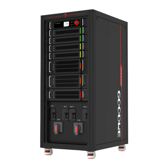
Page 6: Product Overview
1.3 Product Overview ETC series energy storage inverters can be applied in a grid-tied system, an emergency power supply system, or a hybrid system. GW50K-ETC Model GW100K-ETC Brand 50K/100K Power Class Three-phase Hybrid Inverter Cabinet Style Product GW100K-ETC (1) Monitoring Unit (EMS1000) (2) MPPT Module (GW50K-PVM) (3) DC-DC Conversion Module (GW50K-DCM) (4) Power Conversion System Module (5) ON/OFF Grid Switching Module (GW100K-STS) (GW50K-BTM) (7) AC Output Circuit Breaker (GRID) (6) Battery Circuit Breaker (... - Page 7 GW50K-ETC (1) Monitoring Unit (EMS1000) (2) MPPT Module (GW50K-PVM) (3) DC-DC Conversion Module (GW50K-DCM) (4) Power Conversion System Module (5) ON/OFF Grid Switching Module (GW100K-STS) (GW50K-BTM) (7) Load Circuit Breaker (LOAD) (6) AC Output Circuit Breaker (GRID) (9) Battery Circuit Breaker ( BAT) (8) Emergency Stop Button (11) Heat Dissipation Hole (10) MPPT DC Input Circuit Breaker (MPPT)
-
Page 8: Installation Instructions
Dimensions Front Back 750mm 585mm INSTALLATION INSTRUCTIONS 2.1 Select Mounting Location For inverter's protection and convenient maintenance, mounting location for inverter should be selected carefully based on the following rules: Any part of this system shouldn't block the switch and breaker from disconnecting the inverter from DC and AC power. -
Page 9: Mounting
2.2 Mounting Inverter cannot be installed near flammable, explosive or strong electro-magnetic equipment. The inverter is suitable for mounting on concrete or other non-combustible surface only. Fixing the Cabinet Space Requirements Lifting the Cabinet ≥300mm ≥500mm ≥300mm ≥300mm ≥500mm... -
Page 10: Electrical Wiring Connection
2.3 Electrical Wiring Connection 2.3.1 System connection diagrams According to Australian regulations, the N wires on the GRID side and BACK-UP side should be connected to one terminal block. Otherwise, the BACK-UP function may fail. The following diagram shows the wiring connection when the N wire and the PE Cable are connected to the same terminal block. Equipment installed in Australia, New Zealand, South Africa, and so on should follow this diagram. All installations and wiring connections should meet local laws and regulations. Distribution box Back-Up Loads Disconnect this terminal when the N Battery wire and the PE cable are connected Back-Up to the same terminal block. Hybrid Inverter Meter PV String Smart Meter Grid On-Grid N-BAR Link E-BAR E-BAR L1 L2 L3 Normal Loads The following diagram shows the wiring connection when the N wire and the PE Cable are connected separately. -
Page 11: System Application
2.3.2 System Application 1 2 3 4 5 6 7 8 SEMS Router RJ45 GM3000C Main Meter RS485 Grid 485_2 PV String AC Breaker (GRID) LOAD GW50K-ETC: ≥ 125A S1 S2 GW100K-ETC: ≥ 250A DC Breaker AC Breaker (BACK-UP) ≥ 125A AC Breaker GW50K-ETC:... -
Page 12: Electrical Wiring Connection
3. PV string could not connect to earth/grounding conductor. • Before connecting battery,please make sure battery switch is off and battery nominal voltage meet ETC series'specification before connecting batteryto inverter and make sure inverter is isolated form PV and AC power. - Page 13 Connecting the PE Cable L=L1+(1~2)mm 8-10N·m Connecting the AC Output Cable, Load Output Cable, Battery Cable, and PV Input Cable Connection Cable Type Requirements Port GRID Connecting the AC Output Cable L1/L2/L3/N/PE: M8 Screws, tightening Connecting the LOAD Output torque: 8 - 10 N·m LOAD Cable BAT+/BAT-: M8 Screws, tightening...
- Page 14 • The AC output cable, load output cable, DC input cable, and battery cable NOTE are connected to the equipment in the same way. Take the AC output cable connection as an example to explain the connection steps below. • Make sure the following cables are connected correctly to avoid equipment damage. 1. Positive and negative terminals of the battery are connected correctly. 2. Positive and negative terminals of the PV string are connected correctly. 3. AC cable L1, L2, L3 are connected in the correct sequence. 4. Do not mix PE cable and N wire. L=L1+(1~2)mm 120-150mm 8-10N·m...
- Page 15 Communication Line Connections • The wiring methods for connecting communication lines through the terminal block are the same, and this document uses the RS485_1 port connection as an example to illustrate the procedures. • The DRY_OUT, CAN_2, RS485_3, DRY_IN1, DRY_IN2, DRY_IN3 and DRY_ IN4 ports are reserved.
- Page 16 Connecting to the RJ45 Terminal Color Orange&White 1 2 3 4 5 6 7 8 Orange Green&White Blue Blue&White Green Brown&White Brown Compartment Door Install the compartment door after the cable connection is completed. Cut a hole using a utility knife, as the cable inlet hole is not reserved. The hole size should be decided according to the cable diameter to avoid insects or rats that may damage the equipment. D:48mm D:31.4mm D:22mm D:15.2mm...
- Page 17 Special adjustable setting The inverter has a field where the user could set functions, such as trip points, trip time, time of reconnection, active and invalid of QU curve and PU curve. Fuctions can be adjusted through special software. If insterested, please contact with our department of server. Declaration for back-up function The back-up output of ETC hybrid inverters have over load ability.
-
Page 18: Earth Fault Alarm Connection
4. When using anti-reverse function, it would buy about 500W from the grid. 2.4 Earth Fault Alarm Connection ETC series inverter complies with IEC 62109-2 13.9. Fault indicator LED on the inverter cover will light up and the system will email the fault information to customer. -
Page 19: Check Items Before Powering On
Check Items Before Powering On Check Item The inverter is firmly installed. The PE cable, power cable, and communication cable are connected correctly and securely. Cable ties are routed properly and evenly, tied tightly and no burrs. Switches of the upstream and downstream should be all off. The inverter is installed in a proper place where is clean and tidy. -
Page 20: Parameter Setup
After the inverter is powered on, the LCD screen of the monitoring unit automatically turns on and enters the home page. • Access to the settings page requires a password, please contact GOODWE Service Center to obtain the password. 1. Press Enter on the homepage to access the main menu page. -
Page 21: Commissioning Via Pv Master App
1. Edit system configuration to make the system work as customer needs. 0.00 2. Monitor and check the performance of the Hybrid system. 0.02 Safety Country 50Hz Grid Default Please download "PV Master App" from www.goodwe.com or scan the QR Battery Type Work Model General Mode code. Meter Status... -
Page 22: Others
Others 7 .1 Error Messages ERROR EXPLANATION REASON SOLUTIONS MESSAGE Utility Phase The sequence of Inverter detects Reverse connection order of L2 and L3 cable. Failure on-grid wire is that phase angle wrong of L2 and L3 are reversed Utility Loss Public grid power Inverter does 1. - Page 23 ERROR EXPLANATION REASON SOLUTIONS MESSAGE Isolation Ground insulation Isolation failure 1. Use multi meter to check if the resistance Failure impedance of could be caused between earth & inverter frame is about zero. If Battery is to low by multiple it's not, please ensure that the connection is well.
- Page 24 Problems During Operation ETC does not start up with only battery Solution: Make sure the voltage of battery is higher than 200V, otherwise battery cannot start ETC up. High power fluctuation on battery charge or discharge: Solution: Check if there is a fluctuation on load power. Battery does not charge: Solution: Make sure BMS communication is OK on the LCD screen.
- Page 25 100% follow the instructions, please contact after-sales. Disclaimer The ETC series inverters are transported, used and operated under environmental and electrical conditions. Manufacturer has the right not to provide after-sales services or assistance under following conditions: •...
-
Page 26: Technical Parameters
7.2 Technical Parameters Technical Data GW50K-ETC Battery Input Data Battery Type Li-Ion Nominal battery voltage (V) Battery voltage range (V) 200~865 Max. continuous Charging Current (A) Max. continuous Discharging Current (A) Max charge power (W) Max discharge power (W) PV String Input Data Max.Input Power (W) Max.Input Voltage (V) 1000... - Page 27 AC Grid Frequency Range (Hz) 47~52(AS);47.5~51.5(Germany) Max. AC Current Output to Utility Grid (A) Max. AC Current From Utility Grid (A) Max. Output Fault Current(peak and 156A@150us duration) (A) Inrush Current(peak and duration) (A) Nominal Output Current (A) 72.5 Output Power Factor ~1 (Adjustable from 0.8 leading to 0.8 lagging) Max.
- Page 28 Rapid Shutdown Optional Remote Shutdown Integrated PID Recovery Optional I-V Curve Scan Optional I-V Curve Diagnosis Optional General Data Operating Temperature Range (℃) -20~+60℃(>45℃ derating) Relative Humidity 0~95% (Non-condensing) Max. Operating Altitude (m) 4000 Cooling Method Fan Cooling User Interface LCD &...
-
Page 29: Other Test
7.3 Other Test For Australian requirements, in the THDi test, Zref should be added between inverter and mains. RA, XA for Line conduvtor RN, XN for Neutral conductor Zref: RA=0, 24; XA=j0,15 at 50Hz; RN=0, 16; XN=j0,10 at 50Hz 7.4 Quick Check List to Avoid Danger 1. Inverter cannot be installed near flammable, explosive or strong electro-magnetic equipment. - Page 30 Moisture location category definition Level Moisture Parameters 4K4H ~20~+55℃ Temperature Range 0~+40℃ -33~+40℃ Moisture Parameters 5%~85% 15%~100% 4%~100% Environment category definition Environment Ambient Termperature Relative Humidity Applied to Condition Outdoor -20~50℃ 4%~100% Indoor Unconditioned -20~50℃ 5%~95% Indoor conditioned 0~40℃ 5%~85% Pollution degree definition No pollution or only dry, non-conductive polllution occurs.
- Page 31 Device info SN : 9050KETC 20A 80001 Status: Normal Communicate info Safety Code: 50Hz Grid Network: Settings Server: tcp.goodwe.power.com Maintenance Wait down down 2020/11/20 16 :00:00 2020/11/20 16 :00:00 2020/11/20 16 :00:00 2020/11/20 16 :00:00 2020/11/20 16 :00:00 Long press...
- Page 32 SEMS Portal App SEMS Portal website LinkedIn Offical website PV Master App www.semsportal.com GoodWe Technologies Co.,Ltd. No. 90 Zijin Rd., New District, Suzhou, 215011, China www.goodwe.com service@goodwe.com...
Need help?
Do you have a question about the ETC Series and is the answer not in the manual?
Questions and answers