Goodwe ET Series User Manual
Hybrid inverter 15-30kw
Hide thumbs
Also See for ET Series:
- User manual ,
- Quick installation manual (37 pages) ,
- Connection manual (3 pages)
Table of Contents
Advertisement
Quick Links
Advertisement
Table of Contents

Related Manuals for Goodwe ET Series


Summary of Contents for Goodwe ET Series
- Page 1 User Manual Hybrid Inverter ET Series 15-30kW V1.0-2022-8-30...
- Page 2 Copyright©GoodWe Technologies Co., Ltd. All rights reserved. No part of this manual can be reproduced or transmitted to the public platform in any form or by any means without the prior written authorization of GoodWe Technologies Co.,Ltd. Trademarks and other GOODWE trademarks are trademarks of GoodWe Technologies GoodWe Technologies Co.,Ltd.
- Page 3 CONTENT User Manual V1.0-2022-08-30 CONTENT...
- Page 4 CONTENT User Manual V1.0-2022-08-30...
-
Page 5: About This Manual
1 About This Manual This manual describes the product information, installation, electrical connection, commissioning, troubleshooting, and maintenance. Read through this manual before product features, functions, and safety precautions. This manual is subject to update without https://en.goodwe.com. 1.1 Applicable Model Model Nominal Output Power... - Page 6 01 About This Manual User Manual V1.0-2022-08-30 DANGER WARNING CAUTION NOTICE 1.4 Updates The latest document contains all the updates made in earlier issues. V1.0 2022-08-30 • First Issue...
-
Page 7: Safety Precaution
• familiar with local standards and safety regulations. • • not follow the instructions. https://en.goodwe.com/ warranty. 2.2 PV String Safety DANGER happen if other types of DC terminals are used, which are beyond the manufacturer’s liability. WARNING • Ensure the component frames and the bracket system are securely grounded. -
Page 8: Inverter Safety
02 Safety Precaution User Manual V1.0-2022-08-30 2.3 Inverter Safety WARNING • • output current. • • • DANGER • • Delayed discharge. Wait 5 Disconnect all incoming the components are completely product before working on it. discharged. Read through the user Potential risks exist. -
Page 9: Battery Safety
• • 2.5 Personnel Requirements NOTICE • safety precautions and correct operations. • 2.6 EU Declaration of Conformity • • • • • • • • • You can download the EU Declaration of Conformity on https://en.goodwe.com. -
Page 10: Product Introduction
Model • GW15K-ET • GW20K-ET • GW25K-ET • GW29.9K-ET • GW30K-ET Model description GW15K-ET Referring to Explanation Brand Code GW: GoodWe Rated Power 15K: the rated power is 15000W. Series Code Supported Grid Types TN-S TN-C TN-C-S... -
Page 11: Application Scenarios
User Manual V1.0-2022-08-30 03 Product Introduction 3.2 Application Scenarios WARNING • the system is disconnected. • • • • shutdown function may fail. • • • loads as below: • unstable. •... - Page 12 03 Product Introduction User Manual V1.0-2022-08-30 Self consumption mode PV string & rapid shutdown module ON-GRID Utility meter Utility grid breaker Load breaker Battery breaker ON-GRID load Battery Power cable Signal cable Parts Description PV string & rapid shutdown module can be obtained from the packing box.
-
Page 13: System Working Mode
User Manual V1.0-2022-08-30 03 Product Introduction 3.3 Working Mode 3.3.1 System Working Mode Economic mode NOTICE • Select Economic mode only when it meets the local laws and regulations, e.g., whether the grid is allowed to charge the battery. If not, do not use this mode. •... - Page 14 03 Product Introduction User Manual V1.0-2022-08-30 Self consumption mode NOTICE • For solar power, consider self consumption mode in priority: the excess power charges the • It is suitable for areas with high electricity prices and little or no solar power generation subsidies.
- Page 15 User Manual V1.0-2022-08-30 03 Product Introduction...
- Page 16 03 Product Introduction User Manual V1.0-2022-08-30 Back-up mode NOTICE • The back-up mode is mainly applied to the scenario where the grid is unstable and there • The battery stops discharging when it reaches SOC. When there is sunlight the next day, •...
- Page 17 User Manual V1.0-2022-08-30 03 Product Introduction Peak Shaving mode NOTICE Power limit 300W Time Time Description The PV system charges the battery in priority as the import power from the gird is lower. The grid charges the battery as the import power from the grid is 300W lower than The PV system continues to charge the battery, but the grid stops charging.
-
Page 18: Inverter Operation Mode
03 Product Introduction User Manual V1.0-2022-08-30 3.3.2 Inverter Operation Mode Waiting mode Self-check mode Fault mode Grid-Tied mode Parts Description Waiting mode • When the conditions are met, it enters the self-check mode. • Self-check mode initialization, etc. • When the conditions are met, it enters the grid-tied mode, and the •... - Page 19 User Manual V1.0-2022-08-30 03 Product Introduction 3.4 Features Power derating usage. • • • • • AFCI Reasons to occur electric arcs. • Damaged connectors in the PV or battery system. • Wrong connected or broken cables. • • • phenomenon through the app.
- Page 20 03 Product Introduction User Manual V1.0-2022-08-30 Earth Fault Alarm be noticed. Load Control contactors to enable/disable the load. The load control methods are as follows: • automatically within the setting time period. • loads will be disabled. • grid protection setting. Circuit breaker REY+ REY-...
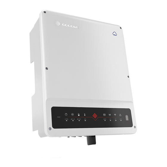
- Page 21 User Manual V1.0-2022-08-30 03 Product Introduction 3.5 Appearance 3.5.1 Parts PV input terminal DC switch lock hole DC switch Communication communication Communication port port Battery input terminal Indicators PE terminal 12. Handle Heat Sink 3.5.2 Dimension 520mm 220mm 200mm 200mm...
- Page 22 03 Product Introduction User Manual V1.0-2022-08-30 3.5.3 Indicators Indicator Status Description mode. mode. grid mode. mode. resetting. communication Termination. Communication fault between the been started yet.
- Page 23 Oper marks Contact information and serial number Good We Tec hno lo gi es Co., Ltd. E-ma il :s er ce @goodwe .c om No.90 Ziji n Rd., New Dis tric t, S uz hou , 2150 11, Chin a...
- Page 24 04 Check and Storage User Manual V1.0-2022-08-30 4 Check and Storage 4.1 Check Before Receiving 1. Check the outer packing box for damage, such as holes, cracks, deformation, and other possible if any damage is found. product and contact the supplier. the supplier as soon as possible if any damage is found.
- Page 25 User Manual V1.0-2022-08-30 04 Check and Storage PV connector *N PV tool *1 Battery tool *1 Battery connector *N 3PIN terminal *1 Screws *3 Insulation board Expansion OT terminal *12 PE terminal *1 Communication Smart meter and Flange nuts for Communication PIN terminal module unlock...
-
Page 26: Installation Requirements
05 Installation User Manual V1.0-2022-08-30 5 Installation 5.1 Installation Requirements Installation Environment Requirements burning. sunshade if it is needed. enough for operations. The temperature and humidity at the installation site should be within the appropriate range. connections, and checking indicators and labels. •... - Page 27 User Manual V1.0-2022-08-30 05 Installation 0%~95%RH Mounting Support Requirements • • • generated by the working product, which may annoy the residents nearby. Installation Angle Requirements • •...
- Page 28 05 Installation User Manual V1.0-2022-08-30 Installation Tool Requirements on site if necessary. RJ45 crimping Goggles Safety shoes Dust mask tool Diagonal pliers Wire stripper Hammer drill Heat gun Vacuum cleaner M3/M5 Heat shrink tube Rubber hammer Cable tie...
-
Page 29: Inverter Installation
User Manual V1.0-2022-08-30 05 Installation 5.2 Inverter Installation 5.2.1 Moving the Inverter CAUTION • • 5.2.2 Installing the Inverter NOTICE • • when drilling holes. • • The DC switch lock of appropriate size should be prepared by customers. The diameter of the lock hole is 5mm. - Page 30 05 Installation User Manual V1.0-2022-08-30 D: 80mm With handles Only for Without handles 1.2~2N·m Only for...
-
Page 31: Electrical Connection
User Manual V1.0-2022-08-30 6 Electrical Connection 6.1 System Wiring Diagram NOTICE • regulations. • is in grid-tied mode, it is closed. • may cause electric shock. N and PE cables are connected together in the Main Panel for wiring. NOTICE •... - Page 32 06 Electrical Connection User Manual V1.0-2022-08-30 N and PE cables are separately wired in the Main Panel. NOTICE • • function may be abnormal in case of grid failure. • In Germany, the internal relay will connect the N wire and PE cable in back-up mode in 100ms.
- Page 33 User Manual V1.0-2022-08-30 6.2 Safety Precaution DANGER • Perform electrical connections in compliance with local laws and regulations. Including • before any electrical connections. Do not work with power on. Otherwise, an electric shock may occur. • Do not place the cables entangled or crossed. •...
- Page 34 06 Electrical Connection User Manual V1.0-2022-08-30 L=L1+(1-2)mm L1 Copper, 4mm S 6mm 1.2~2N·m 6.4 Connecting the DC Input Cable(PV) DANGER • • property losses. within the permissible range. WARNING The PV strings cannot be grounded. Ensure the minimum insulation resistance of the...
- Page 35 User Manual V1.0-2022-08-30 7-8mm 7-8mm S 6mm Click Click 1000V...
-
Page 36: Connecting The Battery Cable
06 Electrical Connection User Manual V1.0-2022-08-30 6.5 Connecting the battery cable DANGER • • • downstream&upstream switches, are all disconnected. • Otherwise it may cause electric shock. • • • short circuit to the batteries. • • WARNING • • Ensure that the whole cable cores are inserted into the terminal holes. No part of the cable core can be exposed. - Page 37 User Manual V1.0-2022-08-30 7-8mm 7-8mm 10mm Click Click...
-
Page 38: Connecting The Ac Cable
06 Electrical Connection User Manual V1.0-2022-08-30 6.6 Connecting the AC Cable WARNING residual current exceeds the limit. NOTICE • • breaker in compliance with local laws and regulations. WARNING • • Ensure that the whole cable cores are inserted into the terminal holes. No part of the cable core can be exposed. -
Page 39: Communication Connection
User Manual V1.0-2022-08-30 11-13mm 70-80mm Copper,10mm S 16mm 2-3N·m 3-4N·m 6.7 Communication Connection NOTICE • •... - Page 40 06 Electrical Connection User Manual V1.0-2022-08-30 Function Description REY_OUT2- Dry contact port, which supports connecting additional contactors to enable/disable the load. Power supply 12V_S Controls the RSD Optional. Connects to RSD_12V and 12V_S to RSD_12V modules externally. control the RSD module rapidly. Remote shutdown REY_OUT3- Dry contact...
- Page 41 User Manual V1.0-2022-08-30 6.7.1 Connecting the Communication Cable (Terminal Block) 6-8mm 25mm Dry contact DRED/RCR: 1: REY_OUT2- 2: NC 12: REFGEN 9: REY_OUT3- Power supply 4: GND Remote control 5: 12V_S RSD Control 8: I01 5: 12V_S...
- Page 42 06 Electrical Connection User Manual V1.0-2022-08-30 6.7.2 Connecting the Communication Cable (RJ45 Connector) NOTICE Color EMS/PAR Orange and White Orange 485B3 Green and White Blue Blue and White Green Brown and White SYN_BUS1 Brown SYN_BUS2...
- Page 43 User Manual V1.0-2022-08-30 6.7.3 Connecting the BMS or Meter Communication Cable WARNING NOTICE • • • if you need. • right direction. Please refer to the smart meter user manual for detailed operations. • communication: Color Smart Meter BMS1 BMS2 Orange and White Orange 485_B2...
- Page 44 06 Electrical Connection User Manual V1.0-2022-08-30 Power Limit Network NOTICE networking schemes are: RS485 Utility grid smart meter Loads 6.7.4 Installing the Communication Module (Optional) NOTICE • smartphone or web pages. • •...
-
Page 45: Check Before Power On
User Manual V1.0-2022-08-30 7 Equipment Commissioning 7.1 Check Before Power ON Check Item operate. securely. The electrical conduit holes are sealed. 7.2 Power On Step 1: Step 2: Step 3: Step 4:... -
Page 46: System Commissioning
08 System Commissioning User Manual V1.0-2022-08-30 8 System Commissioning 8.1 Indicators and Buttons Indicator Status Description mode. mode. grid mode. mode. resetting. communication Termination. Communication fault between the been started yet. - Page 47 8.2 Setting Inverter Parameters via PV Master App NOTICE bluetooth, WiFi, 4G or GPRS modules. Commonly used functions: 2. Set grid parameters, communication parameters, safety countries, power limitation, etc. https://en.goodwe. to get the user manual. 8.3 Monitoring via SEMS Portal...
-
Page 48: Maintenance
09 Maintenance User Manual V1.0-2022-08-30 9 Maintenance 9.1 Power OFF the Inverter DANGER • damaged or electric shocks may occur. • Step 1: Step 2: Step 3: Step 4: 9.2 Removing the Inverter WARNING • • Wear proper PPE before any operations. Step 1: communication module, and PE cables. -
Page 49: Troubleshooting
User Manual V1.0-2022-08-30 9.4 Troubleshooting these methods do not work. in analyzing the problem. 3. Utility grid situation. Fault Cause Solutions 1. Utility grid power fails. 1. The alarm is automatically cleared after the grid power supply is restored. Utility Loss disconnected, or 1. - Page 50 09 Maintenance User Manual V1.0-2022-08-30 Fault Cause Solutions 1. If the problem occurs occasionally, the utility grid may be abnormal temporarily. detecting that the utility grid is normal. allowed range. Grid Rapid abnormal or ultra- • Contact the local power company if the high.
- Page 51 User Manual V1.0-2022-08-30 Fault Cause Solutions 1. If the problem occurs occasionally, the utility grid may be abnormal temporarily. detecting that the utility grid is normal. allowed range. Grid 10min • Contact the local power company if the exceeds the range of safety range.
- Page 52 09 Maintenance User Manual V1.0-2022-08-30 Fault Cause Solutions 1. If the problem occurs occasionally, the utility grid may be abnormal temporarily. detecting that the utility grid is normal. Utility grid exception. The permissible range. actual grid • Contact the local power company if the Grid lower than the range.
- Page 53 User Manual V1.0-2022-08-30 Fault Cause Solutions Utility grid exception. The duration of 1. If the problem occurs occasionally, the LVRT the utility grid utility grid may be abnormal temporarily. exception exceeds the set time of detecting that the utility grid is normal. LVRT.
- Page 54 09 Maintenance User Manual V1.0-2022-08-30 Fault Cause Solutions 1. The PE cable of not connected well. 2. The L cable is connected properly. and N cable 2. Check whether the L cable and N cable Ground are connected string is grounded. output of the PV string is grounded.
- Page 55 User Manual V1.0-2022-08-30 Fault Cause Solutions 1. The relay is abnormal or short-circuited. 2. The control circuit is Relay Check abnormal. switch, then connect them 5 minutes later. abnormal connection the problem persists. is abnormal, connection or short circuit. The internal switch, then connect them 5 minutes later.
- Page 56 09 Maintenance User Manual V1.0-2022-08-30 Fault Cause Solutions too high. 2. The sampling switch, then connect them 5 minutes later. the problem persists. abnormal. The PV array Check the serial connection of the PV array. PV Input not correct. Too many PV panels are PV string is not higher than the maximum connected in series...
-
Page 57: Routine Maintenance
User Manual V1.0-2022-08-30 9.5 Routine Maintenance WARNING • • Wear proper PPE before any operations. Maintaining Item Maintaining Method Maintaining Period Check the heat sink, air intake, and air System Clean outlet for foreign matter or dust. DC Switch Once a year working properly. -
Page 58: Technical Parameters
10 Technical Parameters User Manual V1.0-2022-08-30 10 Technical Parameters GW29.9K- GW30K- Technical Data GW15K-ET GW20K-ET GW25K-ET Battery Input Data Battery Type Li-Ion 200~800 50×2 50×2 15,000 20,000 12,500×2 15,000×2 15,000×2 15,000 20,000 12,500×2 15,000×2 15,000×2 PV String Input Data 22,500 30,000 45,000 45,000... - Page 59 User Manual V1.0-2022-08-30 10 Technical Parameters 15,000 20,000 25,000 30,000 30,000 22,500 30,000 33,000 33,000 33,000 380/400, 3L/N/PE 0~300 25.0 33.3 49.8 50.0 34.0 45.0 50.0 50.0 50.0 25.0 33.3 50.0 50.0 30.3 45.3 45.5 Power Factor 0.8 leading~0.8 lagging <3% Distortion AC Output Data (Back-up)
- Page 60 10 Technical Parameters User Manual V1.0-2022-08-30 380/400 <3% 98.0% 99.9% Protection Integrated PV Insulation Resistance Integrated Detection Integrated Integrated Integrated Protection Integrated Integrated Integrated Integrated DC Switch Integrated DC Surge Protection Type II Type III Optional Rapid Shutdown Optional...
- Page 61 User Manual V1.0-2022-08-30 10 Technical Parameters Remote Shutdown Integrated General Data Operating Temperature 0~95% 4000 Smart Fan Cooling Display RS485 WiFi / 4G Communication with Portal <45 Topology Non-isolated Self-consumption at Night <15 Ingress Protection Rating DC Connector 4K4H Pollution Degree Battery: C PV: C...
- Page 62 10 Technical Parameters User Manual V1.0-2022-08-30 Type of Electrical Supply Three phase Grid System China Grid Standards Safety Regulation Output to Utility Grid" by "230V utility gird". *8: No Back-up Output. Feedback.
- Page 63 Website GoodWe Technologies Co., Ltd. No. 90 Zijin Rd., New District, Suzhou, 215011, China www.goodwe.com Local Contacts...
Need help?
Do you have a question about the ET Series and is the answer not in the manual?
Questions and answers