Table of Contents
Advertisement
Quick Links
Advertisement
Table of Contents

Related Manuals for AXIOMTEK SBC81872


Summary of Contents for AXIOMTEK SBC81872
- Page 1 SBC81872 Socket 479 Full-size All-in-One CPU Card Series User’s Manual...
- Page 2 Disclaimers The information in this manual has been carefully checked and is believed to be accurate. AXIOMTEK Co., Ltd. assumes no responsibility for any infringements of patents or other rights of third parties which may result from its use. AXIOMTEK assumes no responsibility for any inaccuracies that may be contained in this document.
-
Page 3: Esd Precautions
Wear a wrist-grounding strap, available from most electronic component stores, when handling boards and components. Trademarks Acknowledgments AXIOMTEK is a trademark of AXIOMTEK Co., Ltd. IBM is a registered trademark of International Business Machines Corporation. MS-DOS, and Windows 2000 are trademarks of Microsoft Corporation. -
Page 4: Table Of Contents
T a b l e o f C o n t e n t s Chapter 1 Introduction General Description Specifications Utilities Supported Board Dimensions Chapter 2 Jumpers and Connectors Board Layout Jumper Settings 2.2.1 LCD Voltage Selection : JP1 2.2.2 Clear CMOS: JP8 2.2.3... - Page 5 4.5.2 Features 4.5.3 VGA/LVDS Panel Connectors Floppy Disk Connector: CN8 Parallel Port Interface: CN15 Serial Port Interface Serial ATA Port 4.10 Keyboard and PS/2 Mouse Connectors 4.11 USB Connector 4.13 ATX SB5V Power Connector 4.14 ATX12V CPU Power Connector: CN4 4.15 Mini-PCI Connector: CN23 4.16...
- Page 6 Advanced Chipset Features Integrated Peripherals Power Management Setup PNP/PCI Configuration PC Health Status 7.10 Load Optimized Defaults 7.11 Supervisor/User Password Setting 7.12 Exit Setting Appendix Watchdog Timer Appendix PCI IRQ Routing...
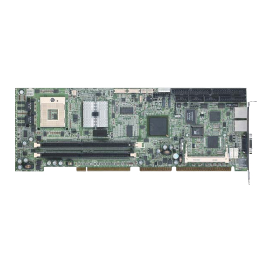
- Page 7 SBC81872 Socket479 All-in-One CPU Card Series User’s Manual C h a p t e r 1 Introduction General Description The SBC81872 CPU card is an industrial grade CPU card ® incorporating the Intel 915GM ChipSet, ensuring its compatibility with PCI bus passive backplanes. Its 8-layer structure reduces signal noise and built-in power management feature.
-
Page 8: Specifications
SBC81872 Socket479 All-in-One CPU Card Series User’s Manual Specifications ® Chipset: Intel 915GM CPU Socket: Socket 479 ® CPU: Intel Socket479 Pentium M FSB400/533MHz L2 Cache: Integrated in CPU BIOS: Phoenix AwardBIOS Rev.6.00 System Memory: 2 x 184-pin DDR DIMM sockets... -
Page 9: Introduction
SBC81872 Socket479 All-in-One CPU Card Series User’s Manual USB Interface: 2 USB ports; USB Spec. Rev. 2.0 compliant. Hardware Monitoring: Controller: Winbond W83627HF-AW detection of CPU temperature, System temperature, Power failure and Fan speed. Watchdog Timer: Generates a system reset Software programmable time interval and hardware reset only. -
Page 10: Board Dimensions
SBC81872 Socket479 All-in-One CPU Card Series User’s Manual Board Dimensions Introduction... -
Page 11: Jumpers And Connectors
SBC81872 Socket479 All-in-One CPU Card Series User’s Manual C h a p t e r 2 Jumpers and Connectors Board Layout Jumpers and Connectors... -
Page 12: Jumper Settings
SBC81872 Socket479 All-in-One CPU Card Series User’s Manual Jumper Settings Making the proper jumper settings configures the SBC81872 to match the needs of your application. The following summary table lists all onboard jumpers and their corresponding functions and/or default settings. -
Page 13: Lcd Voltage Selection : Jp1
SBC81872 Socket479 All-in-One CPU Card Series User’s Manual 2.2.1 LCD Voltage Selection : JP1 Options Settings Short 1-2 3.3V Short 2-3 (Default) 2.2.2 Clear CMOS: JP8 Options Setting Normal Short 1-2 (Default) Clear CMOS Short 2-3 2.2.3 FSB Clock Selection : JP9... -
Page 14: Connectors
SBC81872 Socket479 All-in-One CPU Card Series User’s Manual Connectors The connectors allow the CPU card to connect with other parts of the system. Some problems encountered by your system may be a result from loose or improper connections. Ensure that all connectors are in place and firmly attached. The following table lists the function of each connector on the SBC81872. -
Page 15: Chapter 3 Installation
C h a p t e r 3 Installation This chapter describes the hardware installation procedures on the SBC81872 all-in-one Socket479 CPU card. The following is a list of typical peripherals required to build a minimum system: Power supply and passive backplane IBM™... - Page 16 SBC81872 Socket479 All-in-One CPU Card Series User’s Manual 2.. While gently holding the processor down with your finger, secure the processor in the socket by closing the socket actuator with a screwdriver. Installation...
- Page 17 SBC81872 Socket479 All-in-One CPU Card Series User’s Manual 3..Reattach the cooling system and reassemblethe sytem per documentation that came with the system. Installation...
- Page 18 SBC81872 Socket479 All-in-One CPU Card Series User’s Manual CPU Cooler Installation 1.. For the first time of installation, please do it step by step. 2.. For the second time or later installation, please start from step3. Step1. Remove the liner on the insulator.
- Page 19 SBC81872 Socket479 All-in-One CPU Card Series User’s Manual Step 3. Install the Back-Plate at the backside of the mother board. When the mother board and CPU has been installed in the system, lay the cooler on the CPU. Installation...
- Page 20 SBC81872 Socket479 All-in-One CPU Card Series User’s Manual Step 4. Fasten the cooler on the CPU as follow : Installation...
- Page 21 SBC81872 Socket479 All-in-One CPU Card Series User’s Manual Installation...
-
Page 22: Configuring Power Supply
80-conductor cable (with 40 pin connectors on both ends) is necessary when installing Ultra DMA/66/100 drives. The SBC81872, on this aspect, can support a total of 2 Ultra DMA/66/100 drives. It is through the IDE Connector (CN7) where the 80-conductor cable is connected. The diagram below illustrates the proper installation procedure, including color coding of connectors, of the 80-conductor cable. -
Page 23: Completing Installation
1.Make sure the power is OFF. 2.Set the configuration jumpers according to the jumper settings on Chapter 2. 3.Install the SBC81872 CPU card into one of the slots on the passive backplane. You may allow the SBC81872 to stand alone as a single board computer. - Page 24 SBC81872 Socket479 All-in-One CPU Card Series User’s Manual board. NOTE: The color of pin one is usually red or blue, while others are gray. 5. Turn ON the system power. Installation...
-
Page 25: Hardware Description
CPU on the board. BIOS The system BIOS used in SBC81872 is Award Plug and Play BIOS. The SBC81872 contains a single 4MB Flash EPROM. For more detailed information, refer to Chapter 7 for a complete description of the BIOS setup utility and the available features accompanying it. - Page 26 CN10, Pin 7 is designated as positive (+) pole and Pin 9 as the negative(-) pole Power switch This 2-pin connectoris designed at Pin13 and Pin 14 of CN10 connects the ATX power button of the front panel to the SBC81872 CPU board. Allow user controlling the power on/off Hardware Description...
-
Page 27: Enhanced Ide Interface Connector
SBC81872 Socket479 All-in-One CPU Card Series User’s Manual State of ATX power supply. Enhanced IDE Interface Connector The SBC81872 includes a PCI bus enhanced IDE controller that can support master/slave mode and post write transaction mechanisms with 64-byte buffer, and master data transaction. -
Page 28: 4.5 Display Interface
SBC81872 Socket479 All-in-One CPU Card Series User’s Manual 4.5 Display Interface 4.5.1 Flat Panel/CRT Interface Controller Integrated Display Interface support Analog CRT DAC interface support Support max. DAC frequency up to 400MHZ 24-bit RAMDAC support DDC2B compliant Up to 2048x1536 mode support... - Page 29 SBC81872 Socket479 All-in-One CPU Card Series User’s Manual @Vcc=1.5V depending on the host/memory configurations 3D Render core frequency at 133, 160/166, 200 or 320MHZ @Vcc=1.5V depending on the host/memory configurations Dual Independent display pipes. 32 bit Hardware cursor supported 2D graphics engine...
-
Page 30: Vga/Lvds Panel Connectors
SBC81872 Socket479 All-in-One CPU Card Series User’s Manual 4.6.3 VGA/LVDS Panel Connectors The SBC81872 Series has two connectors that support CRT VGA and LVDS panel displays, individually or simultaneously. CN20 is a D-SUB 15-pin connector commonly used for the CRT VGA display, and CN5 and CN6 are 20-pin and CN11 is 5-pin Hirose connector for LVDS panel connection. -
Page 31: Floppy Disk Connector: Cn8
SBC81872 Socket479 All-in-One CPU Card Series User’s Manual CN6 :Connector for LVDS LCd Channel B Description Description VCCM VCMM VCMM VCMM CLK- CLK+ CN11 :LCD Power Description ENAB Floppy Disk Connector: CN8 The SBC81872 provides a 34-pin header type connector, CN8, Hardware Description... -
Page 32: Parallel Port Interface: Cn15
Write protect # Read data # Side 1 select # Disk change # Parallel Port Interface: CN15 The SBC81872 onboard CN15 is a multi-mode parallel port able to support: Standard mode: IBM PC/XT, PC/AT and PS/2TM compatible with bi-directional parallel... -
Page 33: Serial Port Interface
Printer Select In # Data 3 Data 4 Data 5 Data 6 Data 7 Acknowledge # Busy Paper Empty # Printer Select Serial Port Interface The serial interface onboard SBC81872 consists of COM1 port (CN13) and COM2 (CN14) supports RS-232 Hardware Description... -
Page 34: Serial Ata Port
SBC81872 Socket479 All-in-One CPU Card Series User’s Manual SBC81872 uses two 10-pin connectors for COM1 (CN13) and COM2 (CN14). Interrupt Requests on COM1 and COM2 are selected via IRQ4 and IRQ3 respectively. Additionally, both ports can be enabled or disabled via BIOS setting. -
Page 35: Keyboard And Ps/2 Mouse Connectors
Description SATA_TXP STAT_TXN SATA_RXN SATA_RXP 4.11 Keyboard and PS/2 Mouse Connectors The SBC81872 provides a Mouse (CN21) and Keyboard (CN22) interface with two 5-pin connectors. CN24 is a DIN connector for PS/2 keyboard and mouse connection. CN24 CN21/CN22 Hardware Description... -
Page 36: Usb Connector
SBC81872 Socket479 All-in-One CPU Card Series User’s Manual 4.12 USB Connector The Universal Serial Bus (USB) connector on the SBC81872 is for installation of peripherals supporting the USB interface. CN12 is the 10-pin USB connector on the SBC81872. CN12 USB Power... -
Page 37: Atx Sb5V Power Connector
The specification enables new power management technology to evolve independently in operating systems and hardware while ensuring that they continue to work together. CN1 on the SBC81872 is a 6-pin header connector that provides ATX SB5V Power. 4.14 ATX12V CPU Power Connector This connector CN4 connected to an ATX12V power supply and used for CPU Core Voltage. -
Page 38: Lan External Led: Jp10, Jp11, Jp12, Jp13
SBC81872 Socket479 All-in-One CPU Card Series User’s Manual expansion. You don’t need back plane to have another SCSI card, gigabit LAN card or IDE control card. We prepare these types of mini-PCI card and them can be sold as accessories of SBC81872. -
Page 39: Display Drivers
The GMCH has an integrated 350 MHz RAMDAC that can directly drive a progressive scananalog monitor up to a resolution of 2048x1536 at 60 Hz. Driver Disks’ Contents The driver diskettes that come with the SBC81872 Series package contains the following installation programs: Win2000 driver WinXP driver... -
Page 40: Windows 2000 Vga Driver Installation
SBC81872 Socket479 All-in-One CPU Card Series User’s Manual Windows 2000 VGA Driver Installation To install or upgrade the DirectX driver Microsoft DirectX 8.0a must be installed prior to installing the video driver support on the SBC81872 Series. If you’ve installed a retail version of Windows 2000 you’ll need to install Microsoft DirectX 8.0a. -
Page 41: Windows Xp Vga Driver Installation
SBC81872 Socket479 All-in-One CPU Card Series User’s Manual Windows XP VGA Driver Installation To install video support If you have installed retail Windows you need to install the video driver. The driver is contained in the \SBC81872\Drivers\VGA subdirectory on the dirvers CD. - Page 42 This page does not contain any information.
-
Page 43: Ethernet
C h a p t e r 6 Ethernet Introduction The SBC81872 is equipped with the high performance Plug and Play Ethernet interface which is fully compliant with the IEEE 802.3 standard, and consisting of the RJ-45 connector (CN18 and CN19). - Page 44 This page does not contain any information. Award BIOS setup...
-
Page 45: Award Bios Utility
C h a p t e r 7 Award BIOS Utility Chapter 8 describes the different settings available in the Award BIOS that comes with the SBC81872 CPU card. Also contained here are instructions on how to set up the BIOS configuration. - Page 46 entries, <F1> for help and <Esc> to quit. When you enter the Setup utility, the Main Menu screen will appear on the screen. The Main Menu allows you to select from various setup functions and exit choices. The section below the setup items of the Main Menu displays the control keys for this menu.
-
Page 47: Standard Cmos Setup
SBC81872 Socket479 All-in-One CPU Card Series User’s Manual Standard CMOS Setup “Standard CMOS Setup” allows you to record some basic hardware configurations in your computer system and set the system clock and error handling. If the motherboard is already installed in a working system, you will not need to select this option. - Page 48 Date The date format is <day>, <date> <month> <year>. Press <F3> to show the calendar. The day of week, from Sun to Sat, determined by the BIOS, is read only The date, from 1 to 31 (or the maximum allowed in date the month), can key in the numerical / function key The month, Jan through Dec.
- Page 49 SBC81872 Socket479 All-in-One CPU Card Series User’s Manual Drive A type/Drive B type The category identifies the types of floppy disk drive A or drive B installed in the computer. None No floppy drive installed 360K, 5.25 in 5.25 inch PC-type standard drive; 360Kb capacity 1.2M, 5.25 in...
-
Page 50: Advanced Bios Features
Advanced BIOS Features This section allows you to configure and improve your system and allows you to set up some system features according to your preference. Hard Disk Boot Priority : Press Enter and it shows Bootable add-in card. Virus Warning This item protects the boot sector and partition table of your hard disk against accidental modifications. - Page 51 SBC81872 Socket479 All-in-One CPU Card Series User’s Manual Quick Power On Self Test This option speeds up Power On Self Test (POST) after you turn on the system power. If set as Enabled, BIOS will shorten or skip some check items during POST. The default setting is “Enabled”.
- Page 52 Swap Floppy Drive This allows you to determine whether to enable Swap Floppy Drive or not. When enabled, the BIOS swaps floppy drive assignments so that Drive A becomes Drive B, and Drive B becomes Drive A. By default, this field is set to Disabled. Boot Up Floppy Seek During POST, BIOS will determine the floppy disk drive type, 40 or 80 tracks, installed in the system.
- Page 53 SBC81872 Socket479 All-in-One CPU Card Series User’s Manual PS2 Mouse Function Control If your system has a PS/2 mouse port and you install a serial pointing device, select Disabled. Console Redirection Attempt to redirect console COM port is set to Enable.
-
Page 54: Advanced Chipset Features
Advanced Chipset Features Since the features in this section are related to the chipset on the CPU board and are completely optimized, you are not recommended to change the default settings in this setup table unless you are well oriented with the chipset features. DARM Timing Selectable Select the operating system that is selecting DRAM timing, so select SPD for setting SDRAM timing by SPD... - Page 55 SBC81872 Socket479 All-in-One CPU Card Series User’s Manual DRAM RAS# to CAS# Delay This field let’s you insert a timing delay between the CAS and RAS strobe signals, used when DRAM is written to, read from, or refreshed. Fast gives faster performance; and Slow gives more stable performance.
- Page 56 PCI Express Port 1 to PCI Express Port 4 : These Filed are used to enable or disable the PCI Express function. Onchip VGA Enable/Dis You can use this item to select onchip VGA for the main system VGA. On-chip Frame Buffer Size On-chip Frame buffer size can be set to1MB or 8MB.
- Page 57 SBC81872 Socket479 All-in-One CPU Card Series User’s Manual Panel Number This feature allows user to select the type of the panel which is going to be used on the system. Spread Spectrum If you enable spread spectrum, it can significantly reduce the EMI generated by the system.
-
Page 58: Integrated Peripherals
Integrated Peripherals This option sets your hard disk configuration, mode and port. On-Chip Primary/Secondary PCI IDE The integrated peripheral controller contains an IDE interface with support for two IDE channels. Select Enabled to activate each channel separately. The choice: Enabled, Disabled. On-Chip Serial ATA Select Disabled to disable the onboard SATA. - Page 59 SBC81872 Socket479 All-in-One CPU Card Series User’s Manual Mode, you can’t set the IDE drive to Master Mode. PATA IDE Mode When on chip serial ATA is set as “ Combined Mode “ , this option will be modified. It is used to set the PATA IDE Mode.
- Page 60 Onboard Serial Port 1/Port 2 Select an address and corresponding interrupt for the first and second serial ports. The choice: 3F8/IRQ4, 2E8/IRQ3, 3E8/IRQ4, 2F8/IRQ3, Disabled, Auto. UART Mode Select This item allows you to select UART mode. The choice: IrDA, ASKIR, Normal. UR2 Duplex Mode This item allows you to select the IR half/full duplex funcion.
-
Page 61: Power Management Setup
SBC81872 Socket479 All-in-One CPU Card Series User’s Manual Power Management Setup The Power Management Setup allows you to save energy of your system effectively. It will shut down the hard disk and turn OFF video display after a period of inactivity. - Page 62 HDD Power Down When enabled and after the set time of system inactivity, the hard disk drive will be powered down while all other devices remain active. The choice: Enabled, Disabled. Soft-Off by PWR-BTTN Pressing the power button for more than 4 seconds forces the system to enter the Soft-Off state when the system has “hung.”...
- Page 63 SBC81872 Socket479 All-in-One CPU Card Series User’s Manual Wake-Up By PCI card If this item is enable, it allows the system to resume from a software power down or power saving mode whenever there is an Incoming call to an installed fax/modem. This function needs to be supported by the relevant hardware and software.
-
Page 64: Pnp/Pci Configuration
PNP/PCI Configuration This section describes configuring the PCI bus system. PCI, or Personal Computer Interconnect, is a system which allows I/O devices to operate at speeds nearing the speed the CPU itself uses when communicating with its own special components. This section covers some very technical items and it is strongly recommended that only experienced users should make any changes to the default settings. - Page 65 SBC81872 Socket479 All-in-One CPU Card Series User’s Manual Resource controlled by The Award Plug and Play BIOS has the capacity to automatically configure all of the boot and Plug and Play compatible devices. However, this capability means absolutely nothing unless you are using a Plug and Play operating system such as Windows®98.
-
Page 66: Pc Health Status
PC Health Status This option configures the PCI bus system. All PCI bus systems on the system use INT#, thus all installed PCI cards must be set to this value. Current CPU Temp. The current system CPU temperature will be automatically detected by the system. - Page 67 SBC81872 Socket479 All-in-One CPU Card Series User’s Manual RPM(Revolutions Per Minute) +3.3V/+5V/+12V/-12V/-5V/VBAT(V)/5VSB Show you the voltage of +3.3V/+5V/+12V/-12V/-5V. Award BIOS Setup...
-
Page 68: 7.10 Load Optimized Defaults
7.10 Load Optimized Defaults When you press <Enter> on this item you get a confirmation dialog box with a message similar to: Load Optimized Defaults (Y/N)? N Pressing “Y” loads the default values that are factory settings for optimal performance system operations Award BIOS setup... -
Page 69: 7.11 Supervisor/User Password Setting
SBC81872 Socket479 All-in-One CPU Card Series User’s Manual 7.11 Supervisor/User Password Setting You can set either supervisor or user password, or both of then. The differences between are: Set Supervisor Password: can enter and change the options of the setup menus. - Page 70 prompting only occurs when trying to enter Setup. Award BIOS Setup...
-
Page 71: 7.12 Exit Setting
SBC81872 Socket479 All-in-One CPU Card Series User’s Manual 7.12 Exit Setting Save & Exit Setup Pressing <Enter> on this item asks for confirmation: Save to CMOS and EXIT (Y/N)? Y Pressing “Y” stores the selections made in the menus in CMOS –... -
Page 72: Watchdog Timer
A p p e n d i x A Watchdog Timer Please follow the below WDT process for setup the WDT function. -
Page 73: Pci Irq Routing
SBC81872 Socket479 All-in-One CPU Card Series User’s Manual A p p e n d i x B PCI IRQ ROUTING Device Slot PCI Slot 1 BCDA PCI Slot 2 CDAB PCI Slot 3 DABC PCI Slot 4 ABCD MiniPCI Realtek Lan...
Need help?
Do you have a question about the SBC81872 and is the answer not in the manual?
Questions and answers