Table of Contents
Advertisement
nordictrack.com
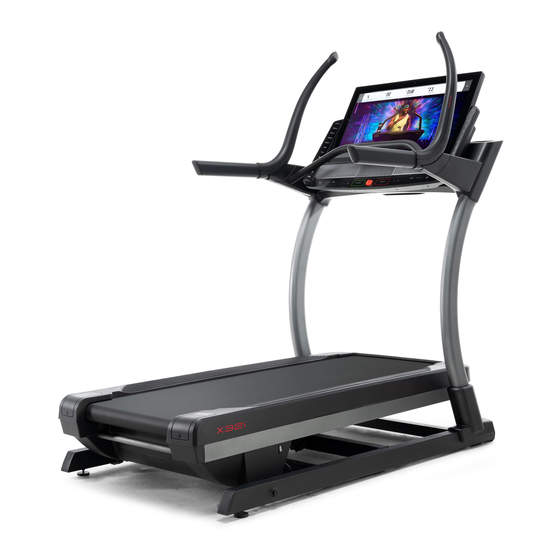
Model No. NTL39221.1
Serial No.
Write the serial number in the space
above for reference.
REGISTER YOUR
PRODUCT
To register your product and
activate your warranty today, go
to my.nordictrack.com.
MEMBER CARE
For service at any time, go to
my.iFIT.com or scan the QR code.
Please do not contact the store.
CAUTION
Read all precautions and
instructions in this manual before
using this equipment. Keep this
manual for future reference.
Serial
Number
Decal
USER'S MANUAL
Advertisement
Table of Contents

Related Manuals for iFIT NordicTrack COMMERCIAL X32i


Summary of Contents for iFIT NordicTrack COMMERCIAL X32i
- Page 1 To register your product and activate your warranty today, go to my.nordictrack.com. MEMBER CARE For service at any time, go to my.iFIT.com or scan the QR code. Please do not contact the store. CAUTION Read all precautions and instructions in this manual before using this equipment.
-
Page 2: Table Of Contents
Apply the decal in the location shown. Note: The decals may not be shown at actual size. NORDICTRACK and IFIT are registered trademarks of iFIT Inc. Google Maps is a trademark of Google LLC. The Bluetooth word mark and logos are registered trademarks of Bluetooth SIG, Inc. and are used under license. -
Page 3: Important Precautions
To reduce the risk of burns, fire, electric shock, or injury to persons, read all important precautions and instructions in this manual and all warnings on your incline trainer before using your incline trainer. iFIT assumes no responsibility for personal injury or property damage sustained by or through the use of this product. - Page 4 18. Do not operate the incline trainer if the (see the drawing on page 6 for the location of power cord or plug is damaged, or if the the power switch), and unplug the power cord incline trainer is not working properly. (See when the incline trainer is not in use.
- Page 5 STANDARD SERVICE PLANS...
-
Page 6: Before You Begin
BEFORE YOU BEGIN Thank you for selecting the revolutionary reading this manual, please see the front cover. To NORDICTRACK COMMERCIAL X32I incline trainer. help us assist you, note the product model number and ® The COMMERCIAL X32I incline trainer offers a selec- serial number before contacting us. -
Page 7: Part Identification Chart
PART IDENTIFICATION CHART Use the drawings below to identify small parts used for assembly. The number in parentheses below each draw- ing is the key number of the part, from the PART LIST near the end of this manual. The number following the key number is the quantity used for assembly. -
Page 8: Assembly
ASSEMBLY 1. To use the assembly steps in this manual, first see the helpful tips below. • Assembly requires two persons. • To identify small parts, see page 7. • Place all parts in a cleared area and remove the •... - Page 9 3. Remove the four 3/8" x 2 3/4" Screws (22) from the Uprights (83). Save the Screws. 4. Set the Uprights (83) on the Base (74). Make sure that the hole with the Upright Wire (75) is on the right side. Attach the right Upright (83) with two of the 3/8"...
- Page 10 5. Connect the Base Wire (52) to the Upright Wire (75). IMPORTANT: The wire connectors should slide together easily and snap into place with an audible click. If they do not, turn one connector and try again. You must connect the wires properly for your incline trainer to function properly.
- Page 11 7. Set the handrail assembly (E) on the floor in the position shown. Attach the Push Bar Top (110) to the Push Bar Bottom (109) with six #8 x 5/8" Machine Screws (106); start all six Machine Screws, and then tighten them. Do not over- tighten the Machine Screws.
- Page 12 9. Slide the Right Inside Upright Cover (70) against the lower end of the right Upright (83). Then, press the Right Outside Upright Cover (71) against the Right Inside Upright Cover until it snaps into place. Make sure that the wires (G) are not pinched, pulled tightly, or resting across the indicated screw (H).
-
Page 13: How To Plug In The Power Cord
HOW TO PLUG IN THE POWER CORD USE A SURGE SUPPRESSOR The outlet must be on a nominal 120-volt circuit capable of carrying 15 or more amps. To avoid Your incline trainer, like other electronic equipment, overloading the circuit, do not plug other electrical can be damaged by sudden voltage changes in your devices, except for low-power devices such as cell home’s power. -
Page 14: How To Use The Incline Trainer
When you use the manual mode of the console, you... - Page 15 HOW TO TURN ON THE CONSOLE HOW TO TURN OFF THE CONSOLE When you are finished using the incline trainer, first IMPORTANT: If the incline trainer has been remove the key from the console and put it in a secure exposed to cold temperatures, allow it to warm to place.
- Page 16 CHANGE CONSOLE SETTINGS on page 22. sled push feature, see page 18. To use a featured workout, see page 18. To create a draw-your-own- map workout, see page 20. To use an iFIT workout, 3. Log into or create an iFIT account. see page 21.
- Page 17 numbered buttons in succession. For example, to HOW TO USE THE MANUAL MODE select a speed setting of 3.5 mph, press the 3 but- ton and then immediately press the 5 button. Note: 1. Insert the key into the console. This feature will not function when the console is See HOW TO TURN ON THE CONSOLE on set to metric units.
- Page 18 6. Follow your progress. HOW TO USE THE SLED PUSH FEATURE The console offers several display modes. The 1. Insert the key into the console. display mode that you select will determine which workout information is shown. See HOW TO TURN ON THE CONSOLE on page 15.
- Page 19 (heart symbol). You must will scale the intensity level of the workout automat- be logged into your iFIT account to save a featured ically based on your manual overrides of the speed workout (see step 3 on page 21).
- Page 20 To use a draw-your-own-map workout, you must be The screen will display the elevation and distance logged into your iFIT account (see step 3 on page 21) statistics for the workout. and the console must be connected to a wireless network (see HOW TO CONNECT TO A WIRELESS 4.
- Page 21 If you have not already done so, touch the menu calendar. button (three horizontal lines symbol) on the screen and then touch Log in to log in to your iFIT account. When the selected date arrives, the iFIT work- Follow the prompts on the screen to enter your out that you scheduled will appear on the home username and password.
- Page 22 (arrow symbol) to return to the home screen. Then, touch the menu button (three horizontal lines For more information about iFIT, go to iFIT.com. symbol) on the screen, and then touch Settings. The settings menu will appear on the screen.
- Page 23 The screen will show the progress of the update. 3. Customize workout settings. When the update is complete, the console will turn To customize workout settings and enable workout off and then turn back on. If it does not, press the features, touch In Workout, and then touch the power switch into the off position.
- Page 24 HOW TO CONNECT TO A WIRELESS NETWORK and an 802.11b/g/n router with SSID broadcast To use iFIT workouts and to use several other features enabled (hidden networks are not supported). of the console, the console must be connected to a wireless network.
- Page 25 HOW TO USE THE FAN HOW TO USE AN OPTIONAL HEART RATE MONITOR The fan has several speed settings, including an auto Whether your mode. While the auto mode goal is to is selected, the speed of the burn fat or to fan will automatically increase strengthen your or decrease as the speed of...
-
Page 26: Fcc Information
FCC INFORMATION This equipment has been tested and found to comply with the limits for a Class B digital device, pursuant to Part 15 of the FCC Rules. These limits are designed to provide reasonable protection against harmful interference in a residential installation. This equipment generates, uses, and can radiate radio frequency energy and, if not installed and used in accordance with the instructions, may cause harmful interference to radio communications. -
Page 27: How To Move The Incline Trainer
HOW TO MOVE THE INCLINE TRAINER Carefully roll the incline trainer on the wheels to the Before moving the incline trainer, insert the key desired location, and then lower it to the level position. into the console (A), raise the incline to the maxi- mum incline level, remove the key, and unplug the CAUTION: To reduce the risk of injury, use extreme power cord. -
Page 28: Maintenance And Troubleshooting
If further c. Remove the key from the console, and then assistance is needed, reinsert it. go to my.iFIT.com, scan the QR code at the right, d. If the incline trainer still will not run, please see the or call 1-833-680-IFIT Member Care contact information at the left. - Page 29 Make sure that the settings for your wireless net- work are correct. c. If you still have questions, go to my.iFIT.com. SYMPTOM: The console does not stay in place a. If the console will not stay in the desired posi-...
- Page 30 SYMPTOM: The walking belt slows when walked on SYMPTOM: The walking belt is off-center or slips when walked on a. Use only a surge suppressor that meets all of the specifications described on page 13. a. If the walking belt is off-center, first remove the key and UNPLUG THE POWER CORD.
-
Page 31: Exercise Guidelines
EXERCISE GUIDELINES Aerobic Exercise—If your goal is to strengthen your WARNING: cardiovascular system, you must perform aerobic Before beginning this exercise, which is activity that requires large amounts or any exercise program, consult your physi- of oxygen for prolonged periods of time. For aerobic cian. - Page 32 SUGGESTED STRETCHES The correct form for several basic stretches is shown at the right. Move slowly as you stretch —never bounce. 1. Toe Touch Stretch Stand with your knees bent slightly and slowly bend forward from your hips. Allow your back and shoulders to relax as you reach down toward your toes as far as possible.
-
Page 33: Part List
PART LIST Model No. NTL39221.1 R1022A Key No. Qty. Description Key No. Qty. Description 3/8" x 5 1/2" Screw Cushion M10 Washer Base Wire 3/8" Star Washer Rubber Cushion #8 x 3/4" Pan Head Tek Screw Large Pivot Bushing #8 x 3/4" Screw Electronics Cover #8 Belt Guide Screw Incline Motor Top Cover... - Page 34 Key No. Qty. Description Key No. Qty. Description Left Outside Handrail Cover 5/16" x 3/4" Screw Left Inside Handrail Cover 5/16" Star Washer Right Outside Handrail Cover #8 x 2" Screw Right Inside Handrail Cover #8 x 1 1/4" Screw Power Converter Board #8 x 5/8"...
-
Page 35: Exploded Drawing
EXPLODED DRAWING A Model No. NTL39221.1 R1022A... - Page 36 EXPLODED DRAWING B Model No. NTL39221.1 R1022A...
- Page 37 EXPLODED DRAWING C Model No. NTL39221.1 R1022A...
- Page 38 EXPLODED DRAWING D Model No. NTL39221.1 R1022A...
- Page 39 EXPLODED DRAWING E Model No. NTL39221.1 R1022A...
-
Page 40: Ordering Replacement Parts
(4) if the product is abused or improperly or abnormally used, (5) if the product is modified to alter function- ality or capability without the written permission of iFIT, or (6) if the product is used for commercial or rental purposes.
Need help?
Do you have a question about the NordicTrack COMMERCIAL X32i and is the answer not in the manual?
Questions and answers