Table of Contents
Advertisement
proform.com
Model No. PFTL12820.8
Serial No.
Write the serial number in the space
above for reference.
Serial
Number
Decal
REGISTER YOUR
PRODUCT
To register your product and
activate your warranty today,
go to my.proform.com.
MEMBER CARE
For service at any time, go to
my.iFIT.com or scan the QR code.
Please do not contact the store.
CAUTION
Read all precautions and
instructions in this manual before
using this equipment. Keep this
manual for future reference.
USER'S MANUAL
Advertisement
Table of Contents

Related Manuals for iFIT PRO-FORM PRO 2000


Summary of Contents for iFIT PRO-FORM PRO 2000
- Page 1 To register your product and activate your warranty today, go to my.proform.com. MEMBER CARE For service at any time, go to my.iFIT.com or scan the QR code. Please do not contact the store. CAUTION Read all precautions and instructions in this manual before using this equipment.
-
Page 2: Table Of Contents
Note: The decal(s) may not be shown at actual size. 305284 PROFORM and IFIT are registered trademarks of iFIT Inc. The Bluetooth word mark and logos are registered ® trademarks of Bluetooth SIG, Inc. and are used under license. Google Maps is a trademark of Google LLC. Wi-Fi... -
Page 3: Important Precautions
To reduce the risk of burns, fire, electric shock, or injury to persons, read all important precautions and instructions in this manual and all warnings on your treadmill before using your treadmill. iFIT assumes no responsibility for personal injury or property damage sus- tained by or through the use of this product. - Page 4 19. Read, understand, and test the emergency 26. When folding or moving the treadmill, make stop procedure before using the treadmill sure that the storage latch is holding the (see HOW TO TURN ON THE POWER on frame securely in the storage position. Do page 19).
-
Page 6: Before You Begin
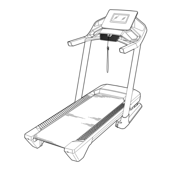
BEFORE YOU BEGIN Thank you for selecting the revolutionary PROFORM reading this manual, please see the front cover of this ® PRO 2000 treadmill. The PRO 2000 treadmill offers an manual. To help us assist you, please note the product impressive selection of features designed to make your model number and serial number before contacting us. -
Page 7: Part Identification Chart
PART IDENTIFICATION CHART Use the drawings below to identify small parts used for assembly. The number in parentheses below each draw- ing is the key number of the part, from the PART LIST near the end of this manual. The number following the key number is the quantity used for assembly. -
Page 8: Assembly
ASSEMBLY • Assembly requires two persons. • To identify small parts, see page 7. • Place all parts in a cleared area and remove the • Left parts are marked “L” or “Left” and right parts packing materials. Do not dispose of the packing are marked “R”... - Page 9 3. Make sure that the power cord is unplugged. Locate the Upright Wire (90) attached to the Base (96) with a tie. Remove the tie. Next, identify the Right Upright (92). Have a second person hold the Right Upright near the Base (96).
- Page 10 5. Identify the Left and Right Base Covers (97, 98). Slide the Left Base Cover onto the Left Upright (91), and slide the Right Base Cover onto the Right Upright (92). Then, slide the Base Covers down to the floor. 6.
- Page 11 7. Set the console assembly (E) facedown on a soft surface to avoid scratching the console assembly. Remove and save the four 5/16" x 3/4" Screws (20). Next, identify the Left and Right Trays (104, 105). Attach the Trays to the console assembly (E) with eight #8 x 3/8"...
- Page 12 9. See the inset drawing. Grip the connector on the end of the Upright Wire (90). Then, press the small latch (F) on the wire pull (D), and remove and discard the wire pull. Next, with the help of a second person, hold the console assembly (E) near the Right Handrail (84).
- Page 13 11. Start two #8 x 1/2" Screws (2) into the Crossbar (89), and then tighten them; do not overtighten the Screws. 12. Align the Left Top Handrail Cover (81) with the Crossbar (89) and with the holes (O) in the Left Handrail (83).
- Page 14 13. Note: If the treadmill is assembled on a smooth surface, it may roll forward as you do this step. Remove the two 5/16" x 3/4" Screws (20) from the Latch Crossbar (59). Note: The Latch Crossbar is not preattached to the treadmill. Next, raise the Frame (64) to the upright posi- tion.
- Page 15 15. Remove the 5/16" Nut (39) and the 5/16" x 2 1/4" Bolt (28) from the bracket on the Latch Crossbar (59). Align the upper end of the Storage Latch (63) with the bracket on the Latch Crossbar (59), and insert the 5/16" x 2 1/4" Bolt (28) through the bracket and the Storage Latch.
- Page 16 17. Firmly tighten the six 3/8" x 3/4" Screws (1). Next, tighten the two 3/8" x 1 3/4" Screws (4); make sure that the Wheels (93) turn freely. Next, set the Right Inner Base Cover (100) onto the lower end of the Right Upright (92) and onto the Base (96).
-
Page 17: How To Use The Treadmill
HOW TO USE THE TREADMILL HOW TO CONNECT THE POWER CORD capable of carrying 15 or more amps. To avoid overloading the circuit, do not plug other electrical Use a Surge Suppressor devices, except for low-power devices such as cell phone chargers, into the surge suppressor or into Your treadmill, like other electronic equipment, can be an outlet on the same circuit. - Page 18 As you exercise, the console will featured workouts. Each workout automatically controls display instant exercise feedback. the speed and incline of the treadmill as an iFIT trainer guides you through an effective exercise session. You can even measure your heart rate when you use a compatible heart rate monitor.
- Page 19 HOW TO TURN ON THE POWER HOW TO USE THE TOUCH SCREEN The console features a tablet with a full-color touch IMPORTANT: If the treadmill has been exposed to screen. The following information will help you become cold temperatures, allow it to warm to room tem- familiar with the tablet’s advanced technology: perature before you turn on the power.
- Page 20 To use the manual mode, see this page. To use a featured workout, see page 22. To create a draw- 1. Connect to your wireless network. your-own-map workout, see page 23. To use an iFIT To use iFIT workouts and to use several other workout, see page 24.
- Page 21 Additional information is also available. To view or 3. Start the walking belt and adjust the speed. browse additional statistics and charts, swipe down Touch Manual Start on the screen or press the from the top of the screen. You can also touch the + button on the screen to view stats or charts.
- Page 22 (heart symbol). You must To end the workout, touch the screen to pause the be logged into your iFIT account to save a featured workout, and then follow the prompts on the screen workout (see step 3 on page 24).
- Page 23 A moment after you touch the button, the HOW TO CONNECT TO A WIRELESS NETWORK on walking belt will begin to move. See step 4 on page page 27). An iFIT account is also required. 22 for more information. 1. Insert the key into the console.
- Page 24 (three horizontal lines symbol) on the screen When the selected date arrives, the iFIT work- and then touch Log in to log in to your iFIT account. out that you scheduled will appear on the home Follow the prompts on the screen to enter your screen.
- Page 25 See step 7 on page 21. Next, touch the menu button (three horizontal lines symbol), and then touch Settings. The settings For more information about iFIT, go to iFIT.com. menu will appear on the screen. 2. Navigate the settings menus and change settings as desired.
- Page 26 Note: Occasionally, a firmware update may cause 3. Customize the time zone and other settings. the console to function slightly differently. These To customize the time zone or other settings, touch updates are always designed to improve your Equipment Settings and then touch the desired exercise experience.
- Page 27 802.11b/g/n router with SSID broadcast Note: If you have questions after following enabled (hidden networks are not supported). these instructions, go to support.iFIT.com for assistance. When a list of networks appears, touch the desired network. Note: You will need to know your network 5.
-
Page 28: Fcc Information
To connect a heart rate monitor to the console, first THE OPTIONAL HEART RATE MONITOR put it on as directed in its included instructions. The Whether your console will search for the heart rate monitor and goal is to connect automatically. burn fat or to strengthen your cardiovascular... -
Page 29: How To Fold And Move The Treadmill
HOW TO FOLD AND MOVE THE TREADMILL HOW TO FOLD THE TREADMILL HOW TO MOVE THE TREADMILL Before moving the treadmill, fold it as described at the To avoid damaging the treadmill, adjust the incline left. CAUTION: Make sure that the storage latch is to zero before you fold the treadmill. -
Page 30: Maintenance And Troubleshooting
If further assistance is needed, d. If the treadmill still will not run, please see go to my.iFIT.com, scan TROUBLESHOOTING at the left for further the QR code at the right, assistance. or call 1-833-680-IFIT (1-833-680-4348). - Page 31 c. Your treadmill features a walking belt coated with SYMPTOM: The treadmill will not connect to the high-performance lubricant. IMPORTANT: Never wireless network apply silicone spray or other substances to a. Make sure that the wireless settings on the console the walking belt or the walking platform unless are correct (see page 27).
- Page 32 b. If the walking belt slips when walked on, first SYMPTOM: The displays of the console do not remove the key and UNPLUG THE POWER function properly CORD. Using the hex key, turn both idler roller screws clockwise, 1/4 of a turn. When the walking a.
-
Page 33: Exercise Guidelines
EXERCISE GUIDELINES Aerobic Exercise—If your goal is to strengthen your WARNING: cardiovascular system, you must perform aerobic Before beginning this exercise, which is activity that requires large amounts or any exercise program, consult your physi- of oxygen for prolonged periods of time. For aerobic cian. -
Page 34: Part List
PART LIST Model No. PFTL12820.8 R1223A Key No. Qty. Description Key No. Qty. Description 3/8" x 3/4" Screw Belt Guide #8 x 1/2" Screw Left Frame Cover #8 x 3/4” Tek Screw Right Frame Cover 3/8" x 1 3/4" Screw Drive Roller/Pulley #8 x 3/4"... - Page 35 Key No. Qty. Description Key No. Qty. Description Grommet Cable Tie Console Key Clip Console Base Hood Clip Left Tray #8 x 5/8" Screw Right Tray Primary Console Fan Screw 5/16" Bushing – (Not Used) Console Frame Cap Round Foot Console Frame U-bracket Console Ground Wire...
-
Page 36: Exploded Drawing
EXPLODED DRAWING A Model No. PFTL12820.8 R1223A... - Page 37 EXPLODED DRAWING B Model No. PFTL12820.8 R1223A 18 18...
- Page 38 EXPLODED DRAWING C Model No. PFTL12820.8 R1223A...
- Page 39 EXPLODED DRAWING D Model No. PFTL12820.8 R1223A...
-
Page 40: Ordering Replacement Parts
This warranty extends only to the original purchaser (customer) and is not transferrable. iFIT’s obligation under this warranty is limited to repairing or replacing, at iFIT’s discretion, the product through one of its authorized service providers. All repairs for which warranty claims are made must be preauthorized by iFIT.
Need help?
Do you have a question about the PRO-FORM PRO 2000 and is the answer not in the manual?
Questions and answers