
Subscribe to Our Youtube Channel
Related Manuals for Keysight S9165A


Summary of Contents for Keysight S9165A
- Page 1 Keysight mmWave Reference Solutions S9165A Transceiver Control Unit This manual provides documentation for the S9165A Transceiver Control Unit GETTING STARTED GUIDE...
- Page 2 Notices commercial computer software CONTAINED HEREIN. SHOULD KEYSIGHT AND THE USER HAVE A documentation. No additional SEPARATE WRITTEN AGREEMENT government requirements beyond © Keysight Technologies, Inc. 2023 WITH WARRANTY TERMS those set forth in the EULA shall No part of this manual may be...
- Page 3 Information on preventing instrument damage can be found at: http://keysight.com/find/PreventingInstrumentRepair Is your product software up-to-date? Periodically, Keysight releases software updates to fix known defects and incorporate product enhancements. To search for software updates for your product, go to the Keysight Technical Support website at: http://www.keysight.com/find/techsupport...
-
Page 5: Table Of Contents
Contents Table of Contents Safety & Environmental Information 7 Warning Statements and Symbols 8 Safety 9 Safety compliance 9 Acoustic statement (European Machinery Directive) 9 General safety notices 9 Weight and Dimensions 10 Handling and lifting 10 Cleaning 11 Environmental Conditions (Operating) 12 Ventilation Requirements 12 Location and Mounting 12 Power requirements 13... - Page 6 Connecting to the RRH 41 The RF cable bundle 41 Making connections in tight spaces 42 Connecting the cable assembly to the RRH 43 Connecting the cable assembly to the S9165A 44 Connecting to the IBU 45 Model F8820A 46 Model F8820B 47...
-
Page 7: Safety & Environmental Information
Keysight Wireless Solutions S9165A Transceiver Control Unit Getting Started Guide 1 Safety & Environmental Information The following topics can be found in this section: “Warning Statements and Symbols” on page 8 “Safety” on page 9 “Weight and Dimensions” on page 10 “Cleaning”... -
Page 8: Warning Statements And Symbols
Safety & Environmental Information Warning Statements and Symbols Warning Statements and Symbols Caution and Warning notices are used in this document are described below. A CAUTION notice denotes a hazard. It calls attention to an operating procedure, practice, or the like that, if not correctly performed or adhered to, could result in damage to the product or loss of important data. -
Page 9: Safety
Safety & Environmental Information Safety Safety This product has been designed and tested in accordance with accepted industry standards, and has been supplied in a safe condition.The documentation contains information and warnings that must be followed by the user to ensure safe operation and to maintain the product in a safe condition. -
Page 10: Weight And Dimensions
For best practice and proper ergonomics, the weight of the components makes it necessary to use caution in handling and lifting: Two persons are needed to lift and carry the S9165A. Use both side-handles when lifting the S9165A. Use a rolling cart when transporting the S9165A. -
Page 11: Cleaning
Safety & Environmental Information Cleaning Cleaning Clean the outside of Keysight products with a soft, lint-free, slightly dampened cloth. Do not use detergent or chemical solvents. To prevent electrical shock, disconnect from Mains before cleaning. Use a dry cloth or one slightly dampened with water to clean the external case parts. -
Page 12: Environmental Conditions (Operating)
10°C from the lowest of the maximum operating temperature of a single instrument. If there are any concerns or special requirements an Keysight Field Engineer should be consulted to assure instrument(s) temperature compliance and performance. -
Page 13: Power Requirements
Safety & Environmental Information Power requirements Power requirements 100/120 VAC, 220/240 VAC 50/60 Hz 1200 W Max (Lower range), 1300 W Max (Upper range) The instrument can operate with mains supply voltage fluctuations up to +/- 10% of the nominal voltage. "WARNING: Safety of any system incorporating the equipment is the responsibility of the assembler of the system."... -
Page 14: Grounding
Safety & Environmental Information Power requirements Grounding This product must be used in a normal condition (all means for protection are intact). Power Strips DO NOT use a power strip which is not suitable for the installation. These devices may not be sufficiently rated to carry the required current and may become a safety hazard. -
Page 15: Ac Power Cord
S9165A080 Transceiver Control Units cabinet when connected to an appropriate power line outlet. Use the Keysight supplied power cord or one with the same or better electrical rating. The cable appropriate to the original shipping location is included with the Keysight S9165A Transceiver Control Unit. -
Page 16: Protecting Against Electrostatic Discharge
Shipping materials and ESD Keysight’s chassis and instrument modules are shipped in materials which prevent static electricity damage. These instruments should only be removed from the packaging in an anti-static area, ensuring that correct anti-static precautions are taken. -
Page 17: Quick Start
Keysight Wireless Solutions S9165A Transceiver Control Unit Getting Started Guide 2 Quick Start The following topics can be found in this section: “Initial Inspection” on page 18 “Options” on page 20 “Purpose and Function” on page 21 “Turn-on Procedure” on page 25... -
Page 18: Initial Inspection
Inspect the shipping container and the cushioning material for signs of stress. Retain undamaged shipping materials for future use, as you may wish to ship the test set to another location or to Keysight Technologies for service. Verify the contents of the container against the table below. -
Page 19: Shipping Problems
— Contact the nearest Keysight Technologies office. — Keep the shipping materials for the carrier’s inspection. — If you must return a test set to Keysight Technologies, use the undamaged original or comparable shipping materials. See “Returning the S9165A for Service”... -
Page 20: Options
Enhanced low phase noise (higher performance than LPN option) S9165A-010 1-channel S9165A; ships with 1 RF cable bundle, and 1 of 8 channel slots filled S9165A-020 2-channel S9165A; ships with 2 RF cable bundles, and 2 of 8 channel slots filled S9165A-030 3-channel S9165A;... -
Page 21: Purpose And Function
Quick Start Purpose and Function Purpose and Function The S9165A Transceiver Control Unit acts as an RF interface between an IF Base Unit (IBU) and 1 to 8 remote radio heads (RRHs). Figure 2-1 S9165A as an RF interface (example with 8 channels) - Page 22 Purpose and Function The S9165A routes Tx and Rx signals between the IBU and the RRH, and controls the RRH (by way of a USB connection). One S9165A can support 1 to 8 channels, with each channel driving one RRH.
-
Page 23: Single-Channel Connections
IBU, and six to the RRH (by way of the RF cable bundle). The USB connection between the S9165A and the RRH is not "plug-and-play". It should be connected before the S9165A is powered up. If it is disconnected during use, the S9165A will have to be rebooted after the connection is re-established. -
Page 24: Multiple-Channel Connections
Figure 2-4 S9165A connections for multiple channels The USB connection between the S9165A and the RRH is not "plug-and-play". It should be connected before the S9165A is powered up. If it is disconnected during use, the S9165A will have to be rebooted after the connection is re-established. -
Page 25: Turn-On Procedure
Turn-on Procedure Turn-on Procedure The S9165A is usually controlled by the connected IBU, rather than directly by the user. However, it does have user-interface features which can be accessed by connecting a monitor to the front-panel display port (item 1 in the illustration below), and also connecting a keyboard and mouse to the front-panel USB ports (items 2 or 3 in the illustration below). -
Page 26: Configuration Tool
— Service Connection Type should be set to Any Click Configure. If the Configuration Successful! message appears, the S9165A will be configured correctly after the next S9165A boot-up, or the next time you click Restart Services on the Service Manager window. (However, if... -
Page 27: Service Manager
The bottom part of the window also shows constantly-updated temperature data for the RRHs and the "LO" modules behind the front panel of the S9165A (see item 2 in the illustration below). If you have made changes using the Configuration Tool, and want them to take effect, click Restart Services (see item 3 in the illustraton below). - Page 28 Quick Start Turn-on Procedure Hardware identification Channel numbers represent the RF ports on the front panel of the S9165A, in scending in numerical order from left to right. Slot numbers represent the physical position of channel modules within the S9165A chassis (this positioning is not visible from the exterior).
-
Page 29: Usb Channel Assignments
Default Load the RRH serial number list which the S9165A creates automatically by scanning current connections. The list will be empty if no such connections have been found. Move the selected serial number entry (that is, the highlighted entry -- click on another entry to select it) up one position in the list. - Page 30 Adds a new entry at the bottom of the list. (The button is disabled when there are already as many entries as the S9165A can support.) The serial number of the new entry is set to “<none>” at first; enter the number of the RRH being connected to that channel. The serial “Valid and invalid...
-
Page 31: Exterior Features
Keysight Wireless Solutions S9165A Transceiver Control Unit Getting Started Guide 3 Exterior Features The following topics can be found in this section: “Front Panel” on page 32 “Labels and Symbols” on page 36... -
Page 32: Front Panel
Exterior Features Front Panel Front Panel The picture below shows the front panel of the S9165A divided into three sections: Figure 3-1 S9165A Front Panel — Section 1: “Front panel: chassis section” on page 33 — Section 2: “Front panel: controller section” on page 34 —... -
Page 33: Front Panel: Chassis Section
This port is used to lock the S9165A frequency reference to an external 10 MHz reference source (typically a reference output from the IBU). 10 MHz Ref This output of the S9165A’s 10 MHz frequency reference can be used for locking other devices to the S9165A. 100 MHz This output of the S9165A’s 100 MHz frequency reference can be used for locking other devices to... -
Page 34: Front Panel: Controller Section
Exterior Features Front Panel Front panel: controller section The features of this section of the S9165A front panel are illustrated and described on the following page. Figure 3-3 S9165A, Controller Features The features are described in the following table. Port/LED... -
Page 35: Front Panel: Channels Section
Channel-specific USB control signal connection to RRH. This USB connection is not "plug-and-play". It should be connected before the S9165A is powered up. If it is disconnected during use, the S9165A will have to be rebooted after the connection is re-established. -
Page 36: Labels And Symbols
Exterior Features Labels and Symbols Labels and Symbols Labels and symbols which may be visible on the exterior of the S9165A are described in the table below. Figure 3-5 S9165A rear panel Symbol Description This symbol is used to indicate power STANDBY mode (yellow in standby, green when instrument is ON) and to mark the position of the instrument power line switch. - Page 37 Exterior Features Labels and Symbols Symbol Description The RCM mark is a registered trademark of the Australian Communications and Media Authority. UK conformity mark is a UK government owned mark. Product showing this mark complay with all applicable UK regulations. South Korean Certification (KC) mark;...
- Page 38 Exterior Features Labels and Symbols Getting Started Guide...
-
Page 39: Connection Procedures
Keysight Wireless Solutions S9165A Transceiver Control Unit Getting Started Guide 4 Connection Procedures The following topics can be found in this section: “Location and Mounting” on page 40 “Connecting to the RRH” on page 41 “Connecting to the IBU” on page 45... -
Page 40: Location And Mounting
Connection Procedures Location and Mounting Location and Mounting If possible, suspend the RRH above the DUT, so that heat given off by it will rise away from the DUT. Leave a minimum clearance of 2.5 inches (7 cm) around the RRH. Ensure that there is enough room to attach all necessary cables between the transceiver and other devices. -
Page 41: Connecting To The Rrh
One end of the cable bundle connects to the S1965A front panel, and the other end connects to the RRH. A quick way to tell them apart is to compare the cable endings with an orange collar: it is labeled "4.8 GHz Out" on the S9165A end, and "Ref In" on the RRH end. -
Page 42: Making Connections In Tight Spaces
Connection Procedures Connecting to the RRH Making connections in tight spaces When attaching cables to threaded connectors, use a torque wrench (90 N-cm, 8 in-lb). Because the ports on an RRH are closely spaced, it is not always easy to tighten connections properly. -
Page 43: Connecting The Cable Assembly To The Rrh
Connection Procedures Connecting to the RRH Connecting the cable assembly to the RRH When attaching cables to threaded connectors, use a torque wrench (90 N-cm, 8 in-lb). Figure 4-4 Cable assembly connections to the RRH 1. Connect the cables in the sequence illustrated above. The name on the cable end must match the name of the port you are connecting it to;... -
Page 44: Connecting The Cable Assembly To The S9165A
Connection Procedures Connecting to the RRH Connecting the cable assembly to the S9165A When attaching cables to threaded connectors, use a torque wrench (90 N-cm, 8 in-lb). 1. Connect the cables in the numerical sequence illustrated below. The name on the cable end must match the name of the port you are connecting it to;... -
Page 45: Connecting To The Ibu
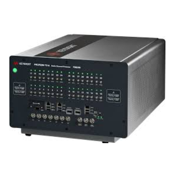
Connecting to the IBU Connecting to the IBU The IBU is typically the Keysight F8820A/F8820B PROPSIM Radio Channel Emulator FS16, which is available in two versions; because the connections are slightly different for these models, they are described separately in the following pages. -
Page 46: Model F8820A
Cable connections to the IBU (Model# F8820A) The USB connection used here is not "plug-and-play". It should be connected before the S9165A is powered up. If it is disconnected during use, the IBU and the S9165A will have to be rebooted after the connection is re-established. -
Page 47: Model F8820B
— Because this IBU model has two LAN ports, it is usually not necessary to use a USB/LAN adpater to connect the S9165A to the IBU. Figure 4-11 Cable connections to the IBU (Model# F8820B) - Page 48 Connection Procedures Connecting to the IBU Getting Started Guide...
-
Page 49: Troubleshooting
Getting Started Guide 5 Troubleshooting The following topics can be found in this section: “Basic Operational Check” on page 50 “Identifying Problems” on page 51 “Where to get technical help” on page 52 “Returning the S9165A for Service” on page 53... -
Page 50: Basic Operational Check
This procedure can be used to establish proper functioning of the system, or to identify specific areas in which there is a problem. Step 1. Disconnect the S9165A from the RRH, and Connect a loopback cable between RRH IF Out and RRH IF In. -
Page 51: Identifying Problems
24.) 2. Are the S9165A, the RRH, and the IBU all powered on? 3. Has the USB cable between the S9165A and the RRH been disconnected since the S9165A booted up? (Any interruption of this connection will require a reboot.) 4. -
Page 52: Where To Get Technical Help
Troubleshooting Where to get technical help Where to get technical help For online assistance: http://www.keysight.com/find/assist To contact Keysight Technologies: http://www.keysight.com/find/contactus Also, see “Locations for Keysight Technologies” on page Getting Started Guide... -
Page 53: Returning The S9165A For Service
Calling Keysight Technologies Keysight Technologies has offices around the world to provide you with complete support for the S9165A. To obtain servicing information, or to order replacement parts, contact the nearest Keysight Technologies office listed under “Locations for Keysight Technologies” on page 54. -
Page 54: Locations For Keysight Technologies
Troubleshooting Returning the S9165A for Service Locations for Keysight Technologies For online assistance: http://www.keysight.com/find/assist To contact Keysight Technologies: http://www.keysight.com/find/contactus Alternately, contact the nearest Keysight sales office: Americas Canada Brazil Mexico (877) 894 4414 55 11 3351 7010 001 800 254 2440... - Page 55 This information is subject to change without notice. © Keysight Technologies 2023 Edition 2, December 2023 S9165-90001 www.keysight.com...
Need help?
Do you have a question about the S9165A and is the answer not in the manual?
Questions and answers