Table of Contents

Related Manuals for Keysight 34941A


Summary of Contents for Keysight 34941A
- Page 1 Keysight 34941A-34942A RF Multiplexer Modules Notice: This document contains references to Agilent. Please note that Agilent’s Test and Measurement business has become Keysight Technologies. For more information, go to www.keysight.com. User’s Guide...
- Page 2 OR OF ANY INFORMATION Edition forth therein, does not require or CONTAINED HEREIN. SHOULD permit, among other things, that KEYSIGHT AND THE USER HAVE A Edition 3, July 2019 Keysight: (1) Furnish technical SEPARATE WRITTEN AGREEMENT Printed in: information related to commercial...
-
Page 3: Safety Symbols
Frame or chassis (ground) terminal Standby supply. Unit is not completely disconnected from ac mains when Caution, risk of electric shock switch is off Caution, risk of danger (refer to this manual for specific Warning or Caution information) Keysight 34941A-34942A User’s Guide... -
Page 4: Additional Safety Notices
Failure to comply with these precautions or with specific warnings or instructions elsewhere in this manual violates safety standards of design, manufacture, and intended use of the instrument. Keysight Technologies assumes no liability of the customer’s failure to comply with the requirements. -
Page 5: Do Not Remove The Instrument Cover
Do Not Modify the Instrument Do not install substitute parts or perform any unauthorized modification to the product. Return the product to an Keysight Sales and Service Office for service and repair to ensure that safety features are maintained. In Case of Damage... -
Page 6: Waste Electrical And Electronic Equipment (Weee) Directive 2002/96/Ec
To return this unwanted instrument, contact your nearest Keysight Service Center, or visit http://about.keysight.com/en/companyinfo/environment/takeback.shtml for more information. Sales and Technical Support To contact Keysight for sales and technical support, refer to the support links on the following Keysight websites: – www.keysight.com/find/xxxxx (product-specific information and support, software and documentation updates) –... -
Page 7: Table Of Contents
........10 34941A and 34942A SCPI Programming Examples . - Page 8 THIS PAGE HAS BEEN INTENTIONALLY LEFT BLANK. Keysight 34941A-34942A User’s Guide...
-
Page 9: Rf Multiplexer Switch Modules
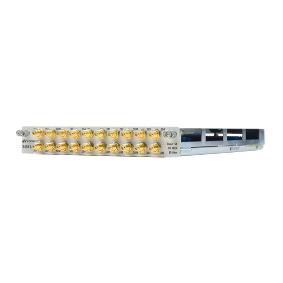
– The 34941A — the 50-Ω version — uses SMA connectors. When installing SMA cables on the 34941A module, it is recommend that you tighten them to 0.8 - 1.1 Nm (7-10 in-lbs) of torque. SMA connectors are easily damaged, especially when tightening a CAUTION neighboring connector with a wrench. -
Page 10: Operating Considerations
With RF MUX switches, you cannot open switches programmatically. You can only close a channel. When you close one channel, another channel automatically opens. Therefore, only one channel relay in each bank is closed at any time. Keysight 34941A-34942A User’s Guide... - Page 11 When installing the plastic shoulder washers, use 7 in-lbs of torque. The 34941A and 34942A are shipped from the factory chassis-grounded with metal shoulder washers installed on all connectors in each bank of relays.
-
Page 12: 34941A And 34942A Scpi Programming Examples
For complete information on the SCPI commands used to program the 34980A, refer to the Keysight 34980A Programmer’s Reference which can be downloaded from www.keysight.com/find/34980A. Example: Closing channels You can only close channels on the RF MUX modules. - Page 13 Note that clearing the cycle count on a specific channel will clear the count on all three relays in the corresponding bank. DIAGnostic:RELay:CYCLes:CLEar (@1103,1201) Example: Resetting module to power-on state The following command resets a module in slot 4 to its power-on state. SYSTem:CPON 4 Keysight 34941A-34942A User’s Guide...
-
Page 14: 34941A And 34942A Simplified Schematic
34941A and 34942A Simplified Schematic Both the 34941A and 34942A modules are configured alike. Each contains four banks of latching switches. Each bank consists of three Form C relays. The front panel of the two RF MUX modules are similar with channel labels in the same positions, the unique product number on the left, and the product description on the right. - Page 15 Index channel relays connectors description electrical isolation grounding mini SMB connectors module descriptions module impedance 34941A 34942A programming examples relay operation safety notices simplified schematics SMA connectors Keysight 34941A-34942A User’s Guide...
- Page 16 THIS PAGE HAS BEEN INTENTIONALLY LEFT BLANK. Keysight 34941A-34942A User’s Guide...
- Page 17 This information is subject to change without notice. Always refer to the Keysight website for the latest revision. © Keysight Technologies 2008-2019 Edition 3, July 2019 Printed in Malaysia *34980-90041* 34980-90041 www.keysight.com...
Need help?
Do you have a question about the 34941A and is the answer not in the manual?
Questions and answers