Table of Contents
Advertisement
A l l t e s t I n s t r u me n t s , I n c .
5 0 0 C e n t r a l A v e .
F a r mi n g d a l e , N J 0 7 7 2 7
P : ( 7 3 2 ) 9 1 9 - 3 3 3 9
F : ( 7 3 2 ) 9 1 9 - 3 3 3 2
a l l t e s t . n e t
s s a l e s @ a l l t e s t . n e t
T h e t e s t & me a s u r e me n t
e q u i p me n t y o u n e e d a t
t h e p r i c e y o u w a n t .
A l l t e s t c a r r i e s t h e w o r l d ' s l a r g e s t s e l e c t i o n o f
u s e d / r e f u r b i s h e d b e n c h t o p t e s t & me a s u r e me n t
e q u i p me n t a t 5 0 % t h e p r i c e o f n e w .
O O u r e q u i p me n t i s g u a r a n t e e d w o r k i n g , w a r r a n t i e d , a n d
a v a i l a b l e w i t h c e r t i f i e d c a l i b r a t i o n f r o m o u r i n - h o u s e s t a f f
o f t e c h n i c i a n s a n d e n g i n e e r s .
• 1 0 + f u l l t i me t e c h n i c i a n s w i t h o v e r 1 5 0 y e a r s o f
s p e c i a l i z a t i o n
• 9 0 d a y w a r r a n t y & 5 d a y r i g h t o f r e t u r n o n a l l
e q u i p me n t
• • 1 - 3 y e a r w a r r a n t i e s f o r n e w a n d
p r e mi u m- r e f u r b i s h e d e q u i p me n t
• E v e r y u n i t t e s t e d t o O E M s p e c i f i c a t i o n s
• S a t i s f a c t i o n g u a r a n t e e d
Y o u h a v e p l a n s , w e w i l l h e l p y o u a c h i e v e t h e m.
A n y p r o j e c t . A n y b u d g e t .
t
G e t a q u o t e t o d a y !
C C a l l ( 7 3 2 ) 9 1 9 - 3 3 3 9 o r e ma i l s a l e s @a l l t e s t . n e t .
Advertisement
Table of Contents

Subscribe to Our Youtube Channel
Related Manuals for Keysight 34922A


Summary of Contents for Keysight 34922A
- Page 1 T h e t e s t & me a s u r e me n t e q u i p me n t y o u n e e d a t t h e p r i c e y o u w a n t . A l l t e s t I n s t r u me n t s , I n c .
- Page 2 Keysight 34921A-34925A Low Frequency Multiplexer Modules User’s Guide...
- Page 3 34980-90021 Software. The EULA and the license set CONTAINED HEREIN. SHOULD Edition forth therein, does not require or KEYSIGHT AND THE USER HAVE A permit, among other things, that SEPARATE WRITTEN AGREEMENT Edition 5, Aug 2022 Keysight: (1) Furnish technical...
-
Page 4: Safety Symbols
Off (mains supply) On (mains supply) Three phase alternating current Presence of a laser device Equipment protected throughout by Protective earth (ground) terminal double insulation or reinforced insulation Product is sensitive to electrostatic Caution, hot surface discharge Keysight 34921A-34925A User’s Guide... -
Page 5: Additional Safety Notices
Failure to comply with these precautions or with specific warnings or instructions elsewhere in this manual violates safety standards of design, manufacture, and intended use of the instrument. Keysight Technologies assumes no liability of the customer’s failure to comply with the requirements. - Page 6 Faulty cables can cause electrical shock and /or fire hazards and could lead to personal injury or death. Safety of any system incorporating the equipment is the responsibility of the WARNING assembler of the system. Keysight 34921A-34925A User’s Guide...
- Page 7 LINE switch (disconnecting device). The instrument power cord does not disconnect or de-energize external circuits connected to the analog bus, terminal blocks or modules. Keysight Customers utilizing the Open Platform Test Systems are classified WARNING as follows and require the user to have the appropriate skillset:...
- Page 8 Failure to do so may result in hazardous conditions such as fire or shock and could lead to personal injury or death. Refer to 34980A Current Limiting Graphs for the current limiting graphs of 34890A. Keysight 34921A-34925A User’s Guide...
- Page 9 WARNING perform any unauthorized modifications to the instrument. Return the instrument to Keysight for service and repair to ensure the safety features are maintained in operational condition. Instruments that appear damaged or defective should be made inoperative and secured against unintended operation.
- Page 10 Do not mount, move or remove any thermocouples when the device under test is connected to a supply source. Keysight 34921A-34925A User’s Guide...
-
Page 11: Environmental Conditions
Environmental Conditions Keysight 34980A is designed for indoor use in an installation category II and low condensation environment. Table below shows the general environmental conditions for this instrument. Refer to the product data sheet at https://literature.cdn.keysight.com/litweb/pdf/5989-1437EN.pdf for more information on the instrument general specifications. -
Page 12: Regulatory Markings
European Legal Standards Association. Directives. The UK conformity mark is a UK The Keysight email address is required government owned mark. Products by EU directives applicable to our showing this mark comply with all product. - Page 13 This mark indicates product has been designed to meet the requirements of Universal recycling symbol. "IP x y", where "x" is the solid particle protection and "y" is the liquid ingress protection. Keysight 34921A-34925A User’s Guide...
-
Page 14: Waste Electrical And Electronic Equipment (Weee) Directive 2002/96/ Ec
Trade in options with Keysight in addition to product takeback instructions. Sales and Technical Support To contact Keysight for sales and technical support, refer to the support links on the following Keysight websites: – www.keysight.com/find/34980a (product-specific information and support, software and documentation updates) –... - Page 15 THIS PAGE HAS BEEN INTENTIONALLY LEFT BLANK. Keysight 34921A-34925A User’s Guide...
-
Page 16: Table Of Contents
........30 34922A 70-Channel Armature Multiplexer ..... .34 34922A Simplified Schematic . - Page 17 ....83 34980A Current Limiting Graphs ......86 Keysight 34921A-34925A User’s Guide...
-
Page 18: Low Frequency Multiplexer Modules
– You can connect a MUX to an external instrument, and/or switch multiple analog signals to the internal DMM. – With the 34921A, 34922A, 34923A, and the 34924A modules, you can close more than one channel in each bank simultaneously (N:1 configuration). -
Page 19: Measurement Functions For The Multiplexer Modules
[d] Impact of higher offset voltage specification (< 50 V) must be taken into consideration. [e] 1 k or higher range used unless 100 series resistors are bypassed on module. [f] 10 k or higher range used for loads over approximately 300 due to series resistance of FET channels. Keysight 34921A-34925A User’s Guide... -
Page 20: Operating Considerations
(faceplate) lose continuity. This prevents signals on the Analog Buses from being present on the D-sub connector pins. Optional terminal blocks available from Keysight automatically provide continuity for these interlock pins. If cables are used, you must provide continuity for the interlock pins in your DUT assembly. See the pinout information later in this guide for the location of interlock pins on each module. - Page 21 Analog Bus relays will be closed. – The simulation setting is stored in volatile memory and will be lost when power is turned off. To re-enable the simulation mode after power has been off, you must send the command again. Keysight 34921A-34925A User’s Guide...
-
Page 22: Scpi Programming Examples For The Multiplexer Modules
MUX section of this manual. For complete information on the SCPI commands used to program the 34980A, with example programs, refer to the Keysight 34980A Programmer’s Reference which can be downloaded from www.keysight.com/find/34980A. Opening and Closing Channels... - Page 23 3 and 8 (of a module in slot 1) into the scan list (and redefines the scan list). The INITiate command scans the specified channels, and then sends the readings to memory. The FETCh? command transfers the readings from memory to the user. Keysight 34921A-34925A User’s Guide...
- Page 24 For the 34923A and the 34925A MUX modules, the query response may include NOTE a suffix to indicate a 1-wire configuration. For example, the response for the 34923A will be either "34923A" (differential mode) or "34923A-1W" (single-ended mode). Keysight 34921A-34925A User’s Guide...
- Page 25 7 and 16 for a MUX module in slot 1. DIAGnostic:RELay:CYCLes:CLEar (@1007,1016) Example: Resetting module(s) to power-on state The following command resets a module in slot 4 to its power-on state. SYSTem:CPON 4 Keysight 34921A-34925A User’s Guide...
-
Page 26: 34921A 40-Channel Armature Multiplexer With Low Thermal Offset
These current channels feature “make-before-break” connections to ensure continuous current flow when switching from one current channel to another. The current fuses are replaceable at servicing at Keysight only. Refer to the 34980A Service Guide for specific information about these fuses. - Page 27 Analog Bus. For more information, see “Safety Interlock” on page 19 and “34921A D-Sub Connectors” on page 28. When power is off, all channel relays maintain state, and the Analog Bus relays open. Keysight 34921A-34925A User’s Guide...
-
Page 28: 34921A Simplified Schematic
NOTE: The three-digit number assigned to each switch represents the channel number. NOTE: Bank Relays: Armature latching Bank 1 Analog Bus Relays: Armature non-latching COM 1 Analog Buses ABus1 ABus2 Current ABus3 ABus4 (MEAS) Current (SENS) Fuse Fuse Fuse Fuse COM 2 Bank 2 Keysight 34921A-34925A User’s Guide... -
Page 29: 34921A D-Sub Connectors
Bank 1 Analog Bus relays to close. The optional 34921T terminal block shorts these pins for you. This feature protects inadvertent routing of high voltages from the Analog Bus to the D-sub connector of the module. Keysight 34921A-34925A User’s Guide... - Page 30 Bank 2 Analog Bus relays to close. The optional 34921T terminal block shorts these pins for you. This feature protects inadvertent routing of high voltages from the Analog Bus to the D-sub connector of the module. Keysight 34921A-34925A User’s Guide...
-
Page 31: 34921T Terminal Block
PC board as shown below. Also shown are two holes that you can use for connecting an external temperature reference to the terminal block. Temperature Sensor External Reference 34921T (viewed from bottom side) Keysight 34921A-34925A User’s Guide... - Page 32 The cables provide communication and power to the temperature sensor on the 34921T terminal block. If cabling is not correct, an error may occur indicating that the 34921A module is not fully operational. Keysight 34921A-34925A User’s Guide...
- Page 33 Never operate the instrument without the terminal block covers securely installed. Use caution to prevent operators from accessing any external circuits, test fixtures, cables or whenever hazardous voltages may be present. Keysight 34921A-34925A User’s Guide...
- Page 34 – AWM Class II B or A/B – external/interconnecting wires (single- or multiple-conductor constructions with a jacket) and potentially subject to mechanical abuse (Canada) – AWM Style Use – external interconnection of electronic equipment or appliances (US) Keysight 34921A-34925A User’s Guide...
-
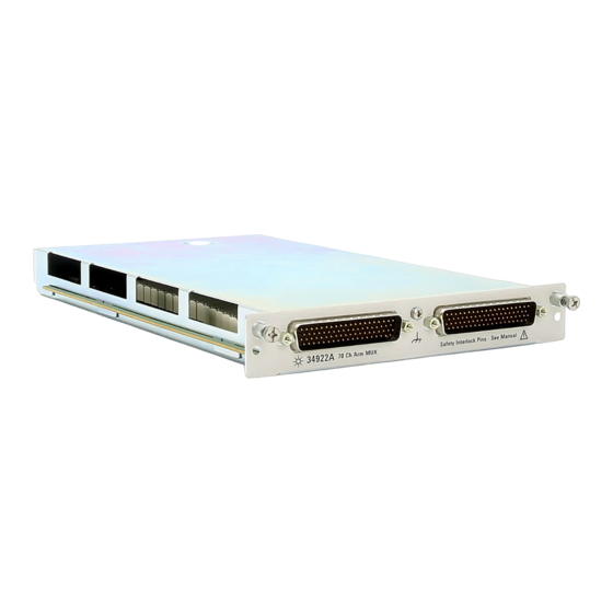
Page 35: 34922A 70-Channel Armature Multiplexer
Using program commands or the mainframe front panel, you can control each of the channel switches individually, and thus configure the 34922A in these modes: – two independent 35-channel 2-wire MUXes. This configuration requires neither using external wiring nor connecting through the internal Analog Buses. -
Page 36: 34922A Simplified Schematic
34922A Simplified Schematic This drawing shows two independent 35-channel 2-wire MUXes. NOTE: The three-digit number assigned to each switch represents the channel number. NOTE: Bank Relays: Armature latching Bank 1 Analog Bus Relays: Armature non-latching COM 1 Analog Buses ABus1... -
Page 37: 34922A D-Sub Connectors
34922A D-Sub Connectors Bank 1 Bank 2 For orientation, the D-sub connector end of the module is facing you. Bank 1 78-Pin D-Sub Male Connector Interlock1 15L Interlock 1 Description Description Description Description Description Description COM1 H COM1 L Interlock 1... - Page 38 78-Pin D-Sub Male Connector 55L Interlock 2 GND 61H 50L Interlock 2 GND 67H Description Description Description Description Description Description COM2 H COM2 L Interlock 2 Interlock 2 No Connect 77 No Connect 78 Keysight 34921A-34925A User’s Guide...
-
Page 39: 34922T Terminal Blocks
This feature protects inadvertent routing of high voltages from the Analog Buses to the D-sub connector of the module. 34922T Terminal Blocks Two terminal blocks are available to facilitate wiring connections to the 34922A module: 34922T-001 (Option 001) - Page 40 Never operate the instrument without the terminal block covers securely installed. Use caution to prevent operators from accessing any external circuits, test fixtures, cables or whenever hazardous voltages may be present. Keysight 34921A-34925A User’s Guide...
- Page 41 – AWM Class II B or A/B – external/interconnecting wires (single- or multiple-conductor constructions with a jacket) and potentially subject to mechanical abuse (Canada) – AWM Style Use – external interconnection of electronic equipment or appliances (US) Keysight 34921A-34925A User’s Guide...
- Page 42 34922T-002 Terminal Block This terminal block with screw-type connections is labeled with the model number and the abbreviated module name. In addition, space is available on the label for you to write the slot number. COM2 36 COM1 Keysight 34921A-34925A User’s Guide...
- Page 43 Never operate the instrument without the terminal block covers securely installed. Use caution to prevent operators from accessing any external circuits, test fixtures, cables or whenever hazardous voltages may be present. Keysight 34921A-34925A User’s Guide...
- Page 44 – AWM Class II B or A/B – external/interconnecting wires (single- or multiple-conductor constructions with a jacket) and potentially subject to mechanical abuse (Canada) – AWM Style Use – external interconnection of electronic equipment or appliances (US) Keysight 34921A-34925A User’s Guide...
-
Page 45: 34923A 40/80-Channel Reed Multiplexer
47 page If you are using an Keysight 34923T-00x terminal block to connect your DUT to this module, be sure to use the terminal block that corresponds to your module configuration mode (Refer to the terminal block drawings on... -
Page 46: Two-Wire Mode
Bank 1 (source) with channel n+20 on Bank 2 (sense) to provide these connections. Four-wire controls occur only when doing 4-wire measurement operations through the internal DMM, such as MEASure:FRESistance? or scanning a channel previously configured as 4-wire. Keysight 34921A-34925A User’s Guide... -
Page 47: One-Wire Mode
These channels are split 20 to a bank. For example, with one Analog Bus relay closed you can close up to a maximum of 39 channel relays. If you try to close more than the allowed number of channels, you will receive an error message. Keysight 34921A-34925A User’s Guide... -
Page 48: 34923A Simplified Schematic For Two- Or Four-Wire Mode
NOTE: Bank Relays: Reed non-latching Analog Bus Relays: Armature non-latching COM 1 100 100 100 100 100 100 Analog Buses ABus1 ABus2 ABus3 ABus4 (MEAS) (SENS) 100 100 100 100 100 100 COM 2 Bank 2 Keysight 34921A-34925A User’s Guide... -
Page 49: 34923A D-Sub Connectors For Two- Or Four-Wire Mode
Bank 1 Analog Bus relays to close. The optional 34923T-001 (for 2-wire) terminal block shorts these pins for you. This feature protects inadvertent routing of high voltages from the Analog Bus to the D-sub connector of the module. Keysight 34921A-34925A User’s Guide... - Page 50 Bank 2 Analog Bus relays to close. The optional 34923T-001 (for 2-wire) shorts these pins for you. This feature protects inadvertent routing of high voltages from the Analog Buses to the D-sub connector of the module. Keysight 34921A-34925A User’s Guide...
-
Page 51: 34923T-001 Terminal Block For Two-Wire Or Four-Wire Mode
Buses. See “Safety Interlock” on page 19 for further information. If you are using an Keysight terminal block to connect your DUT to this module NOTE be sure to use the 34923T-001 terminal block that corresponds to the 2- or 4-wire configuration mode. - Page 52 Never operate the instrument without the terminal block covers securely installed. Use caution to prevent operators from accessing any external circuits, test fixtures, cables or whenever hazardous voltages may be present. Keysight 34921A-34925A User’s Guide...
- Page 53 – AWM Class II B or A/B – external/interconnecting wires (single- or multiple-conductor constructions with a jacket) and potentially subject to mechanical abuse (Canada) – AWM Style Use – external interconnection of electronic equipment or appliances (US) Keysight 34921A-34925A User’s Guide...
-
Page 54: 34923A Simplified Schematic For One-Wire Mode
NOTE: Bank relays: Reed non-latching Analog Bus relays: Armature non-latching COM 1 100 100 100 100 100 100 Analog Buses ABus1 ABus2 ABus3 ABus4 (MEAS) (SENS) 100 100 100 100 100 100 COM 2 Bank 2 Keysight 34921A-34925A User’s Guide... -
Page 55: 34923A D-Sub Connectors For One-Wire Mode
Bank 1 Analog Bus relays to close. The optional 34923T-002 (for 1-wire) shorts these pins for you. This feature protects inadvertent routing of high voltages from the Analog Bus to the D-sub connector of the module. Keysight 34921A-34925A User’s Guide... - Page 56 Bank 2 Analog Bus relays to close. The optional 34923T-002 (for 1-wire) shorts these pins for you. This feature protects inadvertent routing of high voltages from the Analog Buses to the D-sub connector of the module. Keysight 34921A-34925A User’s Guide...
-
Page 57: 34923T-002 Terminal Block For One-Wire Mode
Buses. See “Safety Interlock” on page 19 for further information. If you are using an Keysight terminal block to connect your DUT to this module NOTE be sure to use the 34923T-002 terminal block that corresponds to the 1-wire configuration mode. An error will not be generated if you have installed a terminal block that doesn't match the present module configuration. - Page 58 Never operate the instrument without the terminal block covers securely installed. Use caution to prevent operators from accessing any external circuits, test fixtures, cables or whenever hazardous voltages may be present. Keysight 34921A-34925A User’s Guide...
- Page 59 – AWM Class II B or A/B – external/interconnecting wires (single- or multiple-conductor constructions with a jacket) and potentially subject to mechanical abuse (Canada) – AWM Style Use – external interconnection of electronic equipment or appliances (US) Keysight 34921A-34925A User’s Guide...
-
Page 60: 34924A 70-Channel Reed Multiplexer
In all modes, this module has capability to scan as many as 500 channels/second using the internal DMM. With the automatic “break-before-make” connection operation, you are assured that no two signals are connected to each other during a scan. Keysight 34921A-34925A User’s Guide... - Page 61 Lifetime of relays is severely degraded as current or voltage goes up. If higher voltage is being switched, limits on source current are recommended. When the power is off, all channel and Analog Bus relays open. Keysight 34921A-34925A User’s Guide...
-
Page 62: 34924A Simplified Schematic
Bank relays: Reed non-latching Bank 1 Analog Bus relays: Armature non-latching COM 1 100 100 100 100 100 100 Analog Buses ABus1 ABus2 ABus3 ABus4 (MEAS) (SENS) 100 100 100 100 100 100 COM 2 Bank 2 Keysight 34921A-34925A User’s Guide... -
Page 63: 34924A D-Sub Connectors
Bank 1 78-Pin D-Sub Interlock1 Male Connector GND 26H 15L Interlock 1 GND 32H Description Description Description Description Description Description COM1 H COM1 L Interlock 1 Interlock 1 No Connect 77 No Connect 78 Keysight 34921A-34925A User’s Guide... - Page 64 44L 39H 78-Pin D-Sub 55L Interlock 2 Male Connector GND 61H 50L Interlock 2 GND 67H Description Description Description Description Description Description COM2 H COM2 L Interlock 2 Interlock 2 No Connect 77 No Connect 78 Keysight 34921A-34925A User’s Guide...
-
Page 65: 34924T Terminal Blocks
(no terminal block or cable is connected), the Analog Bus relays are open and disconnected from the Analog Buses. See “Safety Interlock” on page 19 for further information. Keysight 34921A-34925A User’s Guide... - Page 66 Never operate the instrument without the terminal block covers securely installed. Use caution to prevent operators from accessing any external circuits, test fixtures, cables or whenever hazardous voltages may be present. Keysight 34921A-34925A User’s Guide...
- Page 67 – AWM Class II B or A/B – external/interconnecting wires (single- or multiple-conductor constructions with a jacket) and potentially subject to mechanical abuse (Canada) – AWM Style Use – external interconnection of electronic equipment or appliances (US) Keysight 34921A-34925A User’s Guide...
- Page 68 34924T-002 Terminal Block This terminal block with screw-type connections is labeled with the model number and the abbreviated module name. In addition, space is available on the label for you to write the slot number. COM2 36 COM1 Keysight 34921A-34925A User’s Guide...
- Page 69 Never operate the instrument without the terminal block covers securely installed. Use caution to prevent operators from accessing any external circuits, test fixtures, cables or whenever hazardous voltages may be present. Keysight 34921A-34925A User’s Guide...
- Page 70 – AWM Class II B or A/B – external/interconnecting wires (single- or multiple-conductor constructions with a jacket) and potentially subject to mechanical abuse (Canada) – AWM Style Use – external interconnection of electronic equipment or appliances (US) Keysight 34921A-34925A User’s Guide...
-
Page 71: 34925A 40/80-Channel Optically-Isolated Fet Multiplexer
73 page If you are using an Keysight 34925T-00x terminal block to connect your DUT to this module, be sure to use the terminal block that corresponds to your module configuration mode (Refer to the terminal block drawings on... -
Page 72: Four-Wire Mode
This module is interlock protected, which means whenever the D-sub connector end of the modules is exposed, the Analog Bus relays immediately open and disconnect from the Analog Buses. For more information, see “Safety Interlock” page 19. Keysight 34921A-34925A User’s Guide... -
Page 73: Overvoltage Protection
Further FET protection is assured only as one channel in each bank is closed at any time. Thus this module will operate as only a 1:N MUX module. For more information about FET channel closures, refer to page Keysight 34921A-34925A User’s Guide... -
Page 74: 34925A Simplified Schematic For Two- Or Four-Wire Mode
100 Bank relays: FET non-latching Analog Bus relays: Armature non-latching Bank 1 Overvoltage Protection (each channel) COM 1 Analog Buses ABus1 ABus2 ABus3 ABus4 (MEAS) (SENS) COM 2 100 51.1 Bank 2 11 11 Current-Limiting Circuitry Keysight 34921A-34925A User’s Guide... -
Page 75: 34925A D-Sub Connectors For Two- Or Four-Wire Mode
Analog Bus relays: Armature non-latching Bank 1 Overvoltage Protection (each channel) COM 1 Analog Buses ABus1 ABus2 ABus3 ABus4 (MEAS) (SENS) COM 2 100 51.1 Bank 2 11 11 Current-Limiting Circuitry 34925A D-Sub Connectors for Two- or Four-Wire Mode Keysight 34921A-34925A User’s Guide... - Page 76 Bank 1 Analog Bus relays to close. The optional 34925T-001 (for 2-wire) terminal block shorts these pins for you. This feature protects inadvertent routing of high voltages from the Analog Bus to the D-sub connector of the module. Keysight 34921A-34925A User’s Guide...
- Page 77 Bank 2 Analog Bus relays to close. The optional 34925T-001 (for 2-wire) terminal block shorts these pins for you. This feature protects inadvertent routing of high voltages from the Analog Buses to the D-sub connector of the module. Keysight 34921A-34925A User’s Guide...
-
Page 78: 34925T-001 Terminal Block For Two-Wire Or Four-Wire Mode
Buses. See “Safety Interlock” on page 19 for further information. If you are using an Keysight terminal block to connect your DUT to this module NOTE be sure to use the 34925T-001 terminal block that corresponds to the 2- or 4-wire configuration mode. - Page 79 Never operate the instrument without the terminal block covers securely installed. Use caution to prevent operators from accessing any external circuits, test fixtures, cables or whenever hazardous voltages may be present. Keysight 34921A-34925A User’s Guide...
- Page 80 – AWM Class II B or A/B – external/interconnecting wires (single- or multiple-conductor constructions with a jacket) and potentially subject to mechanical abuse (Canada) – AWM Style Use – external interconnection of electronic equipment or appliances (US) Keysight 34921A-34925A User’s Guide...
-
Page 81: 34925A Simplified Schematic For One-Wire Mode
NOTE: Bank relays: FET non-latching 100 Analog Bus relays: Armature non-latching Overvoltage Protection Bank 1 (each channel) COM 1 Analog Buses ABus1 ABus2 ABus3 ABus4 (MEAS) (SENS) COM 2 100 51.1 11 11 Current-Limiting Circuitry Bank 2 Keysight 34921A-34925A User’s Guide... -
Page 82: 34925A D-Sub Connectors For One-Wired Mode
Bank 1 Analog Bus relays to close. The optional 34925T-002 (for 1-wire) terminal block shorts these pins for you. This feature protects inadvertent routing of high voltages from the Analog Bus to the D-sub connector of the module. Keysight 34921A-34925A User’s Guide... - Page 83 Bank 2 Analog Bus relays to close. The optional 34925T-002 (for 1-wire) terminal block shorts these pins for you. This feature protects inadvertent routing of high voltages from the Analog Buses to the D-sub connector of the module. Keysight 34921A-34925A User’s Guide...
-
Page 84: 34925T-002 Terminal Block For One-Wire Mode
Buses. See “Safety Interlock” on page 19 for further information. If you are using an Keysight terminal block to connect your DUT to this module NOTE be sure to use the 34925T-002 terminal block that corresponds to the 1-wire configuration mode. An error will not be generated if you have installed a terminal block that doesn't match the present module configuration. - Page 85 Never operate the instrument without the terminal block covers securely installed. Use caution to prevent operators from accessing any external circuits, test fixtures, cables or whenever hazardous voltages may be present. Keysight 34921A-34925A User’s Guide...
- Page 86 – AWM Class II B or A/B – external/interconnecting wires (single- or multiple-conductor constructions with a jacket) and potentially subject to mechanical abuse (Canada) – AWM Style Use – external interconnection of electronic equipment or appliances (US) Keysight 34921A-34925A User’s Guide...
-
Page 87: 34980A Current Limiting Graphs
1A (switch) / 2A (carry) 1A (switch) / 2A (carry) Multiplexer 34922A 60VA per channel 60VA per channel 1000Vpk Terminal Block 34922T Volt-Hertz limit: 10 Volt-Hertz limit: 10 Initial closed channel resistance: Initial closed channel resistance: <1.5 <1.5 Keysight 34921A-34925A User’s Guide... - Page 88 1 week. Switching relays for 2K cycles prior to use may reduce the variation in channel resistance. Keysight recommends the use of 4-wire Ohms for resistance measurements. For high accuracy voltage measurements, select the DMM input resistance setting of >10 G ohms to minimize the impact of relay contact resistance.
- Page 89 / 0.05A (carry) 750Vpk Terminal Block 34924T 10VA per channel 10VA per channel Volt-Hertz limit: 10 Volt-Hertz limit: 10 2,6,7 2,6,7 Initial closed channel resistance Initial closed channel resistance <1.5 / 200 <1.5 / 200 Keysight 34921A-34925A User’s Guide...
- Page 90 1 week. Switching relays for 2K cycles prior to use may reduce the variation in channel resistance. Keysight recommends the use of 4-wire Ohms for resistance measurements. For high accuracy voltage measurements, select the DMM input resistance setting of >10 G ohms to minimize the impact of relay contact resistance.
- Page 91 1 week. Switching relays for 2K cycles prior to use may reduce the variation in channel resistance. Applies to the 34921A and 34922A. Keysight recommends the use of 4-wire Ohms for resistance measurements. For high accuracy voltage measurements, select the DMM input resistance setting of >10 G ohms to minimize the impact of relay contact...
- Page 92 FET protection 34924A connector pinouts description programming examples isothermal block simplified schematic terminal blocks valid measurement operating considerations functions overload protection wiring log overvoltage protection 34925A connector pinouts description overload protection pinouts Keysight 34921A-34925A User’s Guide...
- Page 93 THIS PAGE HAS BEEN INTENTIONALLY LEFT BLANK. Keysight 34921A-34925A User’s Guide...
- Page 94 This information is subject to change without notice. Always refer to the Keysight website for the latest revision. © Keysight Technologies 2008-2022 Edition 5, Aug 2022 Printed in Malaysia 34980-90021 www.keysight.com...
Need help?
Do you have a question about the 34922A and is the answer not in the manual?
Questions and answers