Konica Minolta magicolor 2500W Service Manual
Hide thumbs
Also See for magicolor 2500W:
- User manual (110 pages) ,
- Supplementary manual (48 pages) ,
- Technical manual (35 pages)
Chapters
Table of Contents
Troubleshooting

Related Manuals for Konica Minolta magicolor 2500W


Summary of Contents for Konica Minolta magicolor 2500W
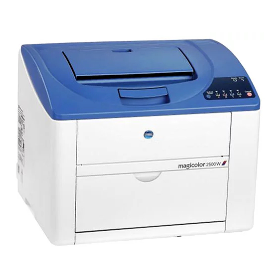
- Page 1 SERVICE MANUAL FIELD SERVICE magicolor 2500W magicolor 2500W ® magicolor 2530 DL magicolor 2530 DL ® magicolor 2550 magicolor 2550 ® magicolor 2550DN magicolor 2550DN ® 2006.08 2006.08 Ver. 1.0 Ver. 1.0...
-
Page 2: Table Of Contents
WARNING INDICATIONS ON THE MACHINE ............S-19 MEASURES TO TAKE IN CASE OF AN ACCIDENT ............S-21 Composition of the service manual ................. C-1 Notation of the service manual ..................C-2 magicolor 2500W/magicolor 2530 DL/magicolor 2550 magicolor 2550DN Main Unit General ........................... 1 Maintenance ........................7 Adjustment/Setting...................... -
Page 4: Safety And Important Warning Items
IMPORTANT NOTICE Because of possible hazards to an inexperienced person servicing this product as well as the risk of damage to the product, KONICA MINOLTA BUSINESS TECHNOLOGIES, INC. (hereafter called the KMBT) strongly recommends that all servicing be performed only by KMBT-trained service technicians. -
Page 5: Safety Warnings
[1] MODIFICATIONS NOT AUTHORIZED BY KONICA MINOLTA BUSINESS TECHNOLOGIES, INC. KONICA MINOLTA brand products are renowned for their high reliability. This reliability is achieved through high-quality design and a solid service network. Product design is a highly complicated and delicate process where numerous mechanical, physical, and electrical aspects have to be taken into consideration, with the aim of arriving at proper tolerances and safety factors. - Page 6 SAFETY AND IMPORTANT WARNING ITEMS [2] POWER PLUG SELECTION In some countries or areas, the power plug provided with the product may not fit wall outlet used in the area. In that case, it is obligation of customer engineer (hereafter called the CE) to attach appropriate power plug or power cord set in order to connect the product to the supply.
- Page 7 SAFETY AND IMPORTANT WARNING ITEMS [3] CHECKPOINTS WHEN PERFORMING ON-SITE SERVICE KONICA MINOLTA brand products are extensively tested before shipping, to ensure that all applicable safety standards are met, in order to protect the customer and customer engi- neer (hereafter called the CE) from the risk of injury. However, in daily use, any electrical equipment may be subject to parts wear and eventual failure.
- Page 8 SAFETY AND IMPORTANT WARNING ITEMS Power Plug and Cord WARNING • When using the power cord set (inlet type) that came with this product, make sure the connector is securely inserted in the inlet of the product. When securing measure is provided, secure the cord with the fixture properly.
- Page 9 SAFETY AND IMPORTANT WARNING ITEMS Wiring WARNING • Never use multi-plug adapters to plug multiple power cords in the same outlet. If used, the risk of fire exists. • When an extension cord is required, use a specified one. Current that can flow in the extension cord is limited, so using a too long extension cord may result in fire.
- Page 10 SAFETY AND IMPORTANT WARNING ITEMS Ventilation CAUTION • The product generates ozone gas during operation, but it will not be harmful to the human body. If a bad smell of ozone is present in the following cases, ventilate the room. a.
- Page 11 SAFETY AND IMPORTANT WARNING ITEMS Work Performed with the Product Powered On WARNING • Take every care when making adjustments or performing an operation check with the product powered. If you make adjustments or perform an operation check with the external cover detached, you may touch live or high-voltage parts or you may be caught in moving gears or the timing belt, leading to a risk of injury.
- Page 12 SAFETY AND IMPORTANT WARNING ITEMS Safety Checkpoints WARNING • Check electrode units such as a charging corona unit for deterioration and sign of leakage. Current can leak, leading to a risk of trouble or fire. • Before disassembling or adjusting the write unit (P/H unit) incorporating a laser, make sure that the power cord has been disconnected.
- Page 13 SAFETY AND IMPORTANT WARNING ITEMS Safety Checkpoints WARNING • Make sure that all screws, components, wiring, connec- tors, etc. that were removed for safety check and mainte- nance have been reinstalled in the original location. (Pay special attention to forgotten connectors, pinched cables, forgotten screws, etc.) A risk of product trouble, electric shock, and fire exists.
- Page 14 SAFETY AND IMPORTANT WARNING ITEMS Handling of Service Materials CAUTION • Use only a small amount of cleaner at a time and take care not to spill any liquid. If this happens, immediately wipe it off. A risk of fire exists. •...
- Page 15 SAFETY AND IMPORTANT WARNING ITEMS [4] Laser Safety • This is a digital machine certified as a Class 1 laser product. There is no possibility of danger from a laser, provided the machine is serviced according to the instruction in this manual.
- Page 16 SAFETY AND IMPORTANT WARNING ITEMS U.S.A., Canada (CDRH Regulation) • This machine is certified as a Class 1 Laser product under Radiation Performance Stan- dard according to the Food, Drug and Cosmetic Act of 1990. Compliance is mandatory for Laser products marketed in the United States and is reported to the Center for Devices and Radiological Health (CDRH) of the U.S.
- Page 17 SAFETY AND IMPORTANT WARNING ITEMS Finland, Sweden LUOKAN 1 LASERLAITE KLASS 1 LASER APPARAT VAROITUS! • Laitteen käyttäminen muulla kuin tässä käyttöohjeessa mainitulla tavalla saat- taa altistaa käyttäjän turvallisuusluokan 1 ylittävälle näkymättömälle laser- säteilylle. puolijohdelaser Laserdiodin suurin teho 10 mW aallonpituus 775-800 nm VARNING!
- Page 18 SAFETY AND IMPORTANT WARNING ITEMS Laser Safety Label • A laser safety label is attached to the inside of the machine as shown below. 4139safe001c0 S-15...
- Page 19 SAFETY AND IMPORTANT WARNING ITEMS Laser Caution Label • A laser caution label is attached to the outside of the machine as shown below. A. magicolor 2500W A00Vsafe001e0 B. magicolor 2530 DL A00Vsafe002e0 S-16...
- Page 20 SAFETY AND IMPORTANT WARNING ITEMS C. magicolor 2550 A00Vsafe003e0 D. magicolor 2550DN A00Vsafe004e0 S-17...
- Page 21 SAFETY AND IMPORTANT WARNING ITEMS PRECAUTIONS FOR HANDLING THE LASER EQUIPMENT • When laser protective goggles are to be used, select ones with a lens conforming to the above specifications. • When a disassembly job needs to be performed in the laser beam path, such as when working around the printerhead and PC Drum, be sure first to turn the printer OFF.
-
Page 22: Warning Indications On The Machine
SAFETY AND IMPORTANT WARNING ITEMS WARNING INDICATIONS ON THE MACHINE Caution labels shown are attached in some areas on/in the machine. When accessing these areas for maintenance, repair, or adjustment, special care should be taken to avoid burns and electric shock. High temperature High voltage 4139safe009c0... - Page 23 SAFETY AND IMPORTANT WARNING ITEMS High voltage 4139safe010c0 CAUTION: • You may be burned or injured if you touch any area that you are advised not to touch by any caution label. Do not remove caution labels. If any caution label has come off or become dirty and therefore the caution cannot be read, contact our Service Office.
-
Page 24: Measures To Take In Case Of An Accident
MEASURES TO TAKE IN CASE OF AN ACCIDENT MEASURES TO TAKE IN CASE OF AN ACCIDENT 1. If an accident has occurred, the distributor who has been notified first must immediately take emergency measures to provide relief to affected persons and to prevent further damage. - Page 25 MEASURES TO TAKE IN CASE OF AN ACCIDENT Blank Page S-22...
-
Page 26: Composition Of The Service Manual
Composition of the service manual This service manual consists of Theory of Operation section and Field Service section to explain the main machine and its corresponding options. Theory of Operation section gives, as information for the CE to get a full understanding of the product, a rough outline of the object and role of each function, the relationship between the electrical system and the mechanical system, and the timing of operation of each part. -
Page 27: Notation Of The Service Manual
Notation of the service manual A. Product name In this manual, each of the products is described as follows: (1) IC board: Standard printer (2) magicolor 2500W/magicolor 2530 DL Main body magicolor 2550/magicolor 2550DN: (3) Microsoft Windows 95: Windows 95... - Page 28 SERVICE MANUAL FIELD SERVICE magicolor 2500W magicolor 2500W ® ® magicolor 2530 DL magicolor 2530 DL ® ® magicolor 2550 magicolor 2550 ® ® magicolor 2550DN magicolor 2550DN ® ® Main Unit 2006.08 Ver. 1.0...
- Page 29 Revision history After publication of this service manual, the parts and mechanism may be subject to change for improvement of their performance. Therefore, the descriptions given in this service manual may not coincide with the actual machine. When any change has been made to the descriptions in the service manual, a revised version will be issued with a revision mark added as required.
- Page 30 Field Service Ver. 1.0 Aug. 2006 CONTENTS magicolor 2500W/magicolor 2530 DL/magicolor 2550 magicolor 2550DN Main Unit General System configuration....................1 Product specifications ..................... 2 Maintenance Periodic check ......................7 Maintenance items....................7 3.1.1 Parts to be replaced by users (CRUs) ............7 3.1.2...
- Page 31 Torque limiter ....................68 5.3.29 Hard disk kit (Option) .................. 69 Adjustment/Setting How to use the adjustment section ............... 71 Description of the control panel (magicolor 2500W) ..........72 Control panel display ..................72 7.1.1 LED Indicator ....................72 7.1.2 List of status messages ................
- Page 32 Field Service Ver. 1.0 Aug. 2006 7.2.5 Consumables expected life display ............. 76 7.2.6 Consumables counter reset ................ 77 Description of the control panel (magicolor 2530 DL) ........... 80 Control panel display ..................80 8.1.1 Basic screen ....................80 8.1.2 Warning screen ...................
- Page 33 Field Service Ver. 1.0 Aug. 2006 9.5.8 FORCED MODES ..................93 CONSUMABLE USAGE..................94 9.6.1 BLACK TONER................... 94 9.6.2 CYAN TONER..................... 94 9.6.3 MAGENTA TONER ..................94 9.6.4 YELLOW TONER ..................94 9.6.5 DRUM CARTRIDGE ................... 94 DIRECT PRINT ....................94 9.7.1 IMAGE QUALITY ..................
- Page 34 11.8.10 FORMAT ....................119 11.8.11 RESTORE/SAVE ..................120 11.9 LANGUAGE ...................... 120 11.10 ENVIRONMENT MENU..................121 11.10.1 ALTITUDE SETUP ..................121 11.10.2 TRANSFER VOLTAGE................122 11.10.3 DUPLEX DENSITY ................... 122 Service mode (magicolor 2500W)............... 123 12.1 Service mode entry procedure ................. 123...
- Page 35 Undefined misfeed ..................139 Error codes ......................140 16.1 Trouble code ..................... 140 16.1.1 Indication of the error indicator (magicolor 2500W)........140 16.1.2 Indication of the LCD display (magicolor 2530 DL)........141 16.1.3 Indication of the LCD display (magicolor 2550/magicolor 2550DN) ..141 16.1.4...
- Page 36 Field Service Ver. 1.0 Aug. 2006 16.3.1 04: Printer control board malfunction ............145 16.3.2 05: Flash ROM malfunction............... 145 16.3.3 08: Main motor malfunction............... 146 16.3.4 0B: Ventilation fan motor malfunction............146 16.3.5 0C: Power supply cooling fan motor malfunction ........147 16.3.6 10: Polygon motor malfunction..............
- Page 37 Field Service Ver. 1.0 Aug. 2006 19.1.2 White lines in CD, white bands in CD, colored lines in CD, and colored bands in CD ................162 19.1.3 Uneven density in FD................163 19.1.4 Uneven density in CD ................164 19.1.5 Low image density ..................
-
Page 38: General
Field Service Ver. 1.0 Aug. 2006 1. System configuration General System configuration A. magicolor 2500W A00VT2C084AA Main unit Dust cover B. magicolor 2530 DL/magicolor 2550/magicolor 2550DN A00VT2C086AA Duplex Option * Hard Disk Kit ** Dust Cover Main Unit Lower Feeder Unit... -
Page 39: Product Specifications
2 laser diodes and polygon mirror Pc drum type OPC (organic photo conductor) Photoconductor Blade cleaning system cleaning magicolor 2500W/ 2400 dpi x 600 dpi, magicolor 2530 DL 1200 dpi x 600 dpi or 600 dpi x 600 dpi Resolution magicolor 2550/... - Page 40 Field Service Ver. 1.0 Aug. 2006 2. Product specifications B. Functions Warm-up time 110 V/120 V area Average 45 seconds magicolor 2500W/ (at ambient tempera- magicolor 2530 DL 220 V to 240 V area Average 49 seconds ture of 23°C/73.4°F...
- Page 41 10° to 35° C / 50° to 95° F (with a fluctuation of 10° C / 18° F or less per hour) Humidity 15% to 85% (with a fluctuation of 20% or less per hour) F. Controller (1) magicolor 2500W Orignal ASIC Standard memory 32 MB Interface USB 2.0 compliant...
- Page 42 Field Service Ver. 1.0 Aug. 2006 2. Product specifications (3) magicolor 2550/magicolor 2550DN freescale MPC8220i (300 MHz) 128 MB: magicolor 2550 Standard memory 256 MB: magicolor 2550DN USB 2.0 compliant, 10Base-T/ Interfaces 100Base-TX (IEEE 802.3) Ethernet, Parallel, Camera direct print port (magicolor 2550DN only) Printer language PostScript 3 / PCL 6 Windows 98SE/Me/NT4.0 (SP6 or later)/2000 (SP4 or later)/XP (SP1 or later)/...
- Page 43 2. Product specifications Field Service Ver. 1.0 Aug. 2006 Blank Page...
-
Page 44: Maintenance
: Four (Y,M,C,K) toner cartridges are set into a machine destined only for North Amer- ica. : The toner cartridges shipped with the magicolor 2500W/magicolor 2530 DL have a life expectancy of 1,500 printed pages. The toner cartridges shipped with the magicolor 2550/magicolor 2550DN have a life expectancy of 4,500 printed pages. -
Page 45: Parts To Be Replaced By Service Engineers (Frus)
3. Periodic check Field Service Ver. 1.0 Aug. 2006 3.1.2 Parts to be replaced by service engineers (FRUs) Number of No Classification Part name Clean Replace Description prints Monochrome 135,000 Monochrome 45,000 (1P/J Full color 1 Image Transfer belt unit 33,700 transfer section... -
Page 46: Maintenance Parts
: Four (Y,M,C,K) toner cartridges are set into a machine destined only for North Amer- ica. : The toner cartridges shipped with the magicolor 2500W/magicolor 2530 DL have a life expectancy of 1,500 printed pages. The toner cartridges shipped with the magicolor 2550/magicolor 2550DN have a life expectancy of 4,500 printed pages. -
Page 47: Concept Of Parts Life
3. Periodic check Field Service Ver. 1.0 Aug. 2006 Concept of parts life Description Near Life Value Life Value The period of time during which the Main Motor is Drum cartridge 36,000 prints 45,000 prints energized is counted. Fusing unit The number of printed pages is counted. -
Page 48: Maintenance Procedure (Periodic Parts Check)
Field Service Ver. 1.0 Aug. 2006 3. Periodic check Maintenance procedure (Periodic parts check) NOTE • The alcohol referred to in the following procedures is isopropyl alcohol. 3.4.1 Pick-up roller A. Cleaning procedure 1. Open the top cover. 2. Remove the drum cartridge. See P.17 NOTE •... - Page 49 3. Periodic check Field Service Ver. 1.0 Aug. 2006 B. Removal procedure 1. Open the top cover. 2. Remove the drum cartridge. See P.17 NOTE • Position the removed drum car- tridge as shown in the illustration at the left. •...
-
Page 50: Ph Window
4139fs2508c0 3.4.3 Toner Cartridge (C/M/Y/K) A. Removal procedure (1) magicolor 2500W 1. Check the color of the toner car- tridge to be replaced on the control panel. 2. Press the Rotate Toner key and select the color of the toner cartridge to be replaced. - Page 51 3. Periodic check Field Service Ver. 1.0 Aug. 2006 (2) magicolor 2530 DL 1. Check the color of the toner car- tridge to be replaced on the control panel. 2. Select [ENGINE] → [REPLACE TONER] from the menu and select the toner cartridge of the specific color of toner to be replaced.
- Page 52 Field Service Ver. 1.0 Aug. 2006 3. Periodic check 5. Hold onto the handle [1] of the toner cartridge, pull it and remove the toner cartridge [2]. NOTE • When all toner cartridges need to be removed and replaced manually, select [SERVICE MENU] [SRU] [REMOVE ALL].
- Page 53 3. Periodic check Field Service Ver. 1.0 Aug. 2006 3. Remove the protective cover [1]. A00VF2C502DA 4. Aligning the shaft [1] on both sides of the toner cartridge with the rails in the machine, install the toner car- tridge [2]. A00VF2C503DA 5.
-
Page 54: Drum Cartridge
Field Service Ver. 1.0 Aug. 2006 3. Periodic check 3.4.4 Drum cartridge A. Replacement procedure 1. Open the top cover. 2. Hold onto the handle [2] of the drum cartridge [1] and slowly lift the drum cartridge out of the machine. 4139fs2507c0 NOTE •... -
Page 55: 2Nd Transfer Roller
A00VF2C505DA NOTE • When the 2nd transfer roller is replaced with a new one, it is necessary to reset the maintenance counter. For magicolor 2500W: See P.77 For magicolor 2530 DL: See P.128 For magicolor 2550/magicolor 2550DN: See P.130... -
Page 56: Transfer Belt Unit
A00VF2C506DA NOTE • When the transfer belt unit is replaced with a new one, it is necessary to reset the maintenance counter. For magicolor 2500W: See P.78 For magicolor 2530 DL: See P.128 For magicolor 2550/magicolor 2550DN: See P.130... -
Page 57: Fusing Unit
3. Periodic check Field Service Ver. 1.0 Aug. 2006 3.4.7 Fusing unit CAUTION • Before replacing the fusing unit, ensure that it has had time to cool down. A. Replacement procedure 1. Remove the rear cover. See P.31 2. Remove the left cover. See P.32 3. - Page 58 Field Service Ver. 1.0 Aug. 2006 3. Periodic check 7. Remove the transfer belt unit. See P.19 8. Snap off two C-rings [1] of the upper cover [2] and unhook the two fulcrum pins of the upper cover. A00VF2C509DA NOTE •...
- Page 59 3. Periodic check Field Service Ver. 1.0 Aug. 2006 10. Remove two screws [2] from the fus- ing unit [1]. A00VF2C511DA 11. Remove the fusing unit [1]. 12. To reinstall, reverse the order of removal. Precaution for reinstalling the fusing unit •...
-
Page 60: Firmware Upgrade
Field Service Ver. 1.0 Aug. 2006 4. Firmware upgrade Firmware upgrade Image processing board (IPB) firmware upgrading (magicolor 2530 DL) NOTE • The following upgrading procedure applies only to the magicolor 2530 DL. 4.1.1 Upgrading procedure 1. Connect the machine to the PC using an Ethernet cable. (The printer should be ON.) 2. - Page 61 4. Firmware upgrade Field Service Ver. 1.0 Aug. 2006 6. Check with the Command Prompt display on the progress of upgrading procedure. 4138fs2540e0 NOTE • NEVER turn OFF and ON the printer’s power switch until the message “flash update done” appears on the Command Prompt display. 7.
-
Page 62: Image Processing Board (Ipb) Firmware Upgrading (Magicolor 2550/Magicolor 2550Dn)
Field Service Ver. 1.0 Aug. 2006 4. Firmware upgrade Image processing board (IPB) firmware upgrading (magicolor 2550/magicolor 2550DN) 4.2.1 Upgrading procedure A. Parallel connections 1. Connect the machine to the PC using an IEEE 1284 cable. (The printer should be OFF.) 2. - Page 63 4. Firmware upgrade Field Service Ver. 1.0 Aug. 2006 8. Check the message on the control panel and make sure that [IDLE] is displayed. A00VF2C585DA NOTE Do not turn the printer’s power switch OFF while the firmware is upgrading. 9. Print a Configuration Page ([PRINT MENU] → [CONFIGURATION]) and check the firm- ware version to verify the upgrade.
- Page 64 Field Service Ver. 1.0 Aug. 2006 4. Firmware upgrade B. Network connections 1. Connect the machine to the PC using an Ethernet cable. 2. In the Menu, select [PRINT MENU] → [CONFIGURATION] and execute the function. Then, check the IP address [1] of the machine. See P.105 3.
- Page 65 4. Firmware upgrade Field Service Ver. 1.0 Aug. 2006 9. Type “put XXXXX.ps” and press the Enter key. If there are two or more firmware data files involved, repeat the same steps (XXXXXX is the firmware data file name). 4139F2E512DA NOTE Do not turn the printer’s power switch OFF while the firmware is upgrading.
-
Page 66: Other
Field Service Ver. 1.0 Aug. 2006 5. Other Other Disassembly/adjustment prohibited items A. Black-painted screws • Do not remove or loosen any of the black-painted screws in the field. Any of such screws that has been removed calls for readjustment at reinstallation. B. -
Page 67: Disassembly/Assembly List (Other Parts)
5. Other Field Service Ver. 1.0 Aug. 2006 Disassembly/assembly list (other parts) Section Part name Ref.Page Front cover P.33 Right cover P.33 Left cover P.32 Exterior parts Rear cover P.31 Rear panel <*1> P.31 Paper take-up cover P.33 Image processing board P.36 Printer control board P.40... -
Page 68: Disassembly/Assembly Procedure
NOTE • Only for magicolor 2530 DL, magi- color 2550 and magicolor 2550DN. A00VF2C538DA 5.3.2 Rear cover (1) magicolor 2500W 1. Remove four screws [1] and the rear cover [2]. A00VF2C539DA (2) magicolor 2530 DL/magicolor 2550/magicolor 2550DN 1. Remove the rear panel. -
Page 69: Left Cover
5. Other Field Service Ver. 1.0 Aug. 2006 5.3.3 Left cover 1. Open the top cover. 2. Remove two screws [1]. 3. Unlock two tabs [2] and remove the left cover [3]. A00VF2C541DA CAUTION • When installing the left cover, make sure that the harness [1] of the fus- ing unit is located below the rib [2] of the left cover. -
Page 70: Right Cover
Field Service Ver. 1.0 Aug. 2006 5. Other 5.3.4 Right cover 1. Open the top cover. 2. Remove two screws [1]. 3. Unlock two tabs [2] and remove the right cover [3]. A00VF2C542DA 5.3.5 Paper take-up cover 1. Open the paper take-up cover. 2. -
Page 71: Control Panel
A00VF2C535DA 3. Remove four screws [1] and the con- trol panel protective cover [2]. A00VF2C543DA • For magicolor 2500W 4. Remove two screws [1] and discon- nect the connector [2] and remove the control panel [3]. A00VF2C544DA... -
Page 72: Usb Board (Usb)
Field Service Ver. 1.0 Aug. 2006 5. Other • For magicolor 2530 DL/magicolor 2550/magicolor 2550DN 4. Remove three screws [1] and dis- connect the connector [2] and remove the control panel [3]. A00VF2C545DA 5.3.8 USB board (USB) NOTE • The USB board is mounted only on the magicolor 2530 DL and magicolor 2550DN. 1. -
Page 73: Image Processing Board (Ipb)
5. Other Field Service Ver. 1.0 Aug. 2006 5.3.9 Image processing board (IPB) (1) magicolor 2530 DL 1. Remove the rear cover. See P.31 2. Remove the left cover. See P.32 3. Disconnect the connector (PJ21) [1]. A00VF2C550DA 4. Remove three screws [1]. A00VF2C549DA 5. - Page 74 Field Service Ver. 1.0 Aug. 2006 5. Other 6. Disconnect all connectors from the image processing board [1]. A00VF2C552DA 7. Remove six screws [1]. 8. Disconnect the connector (CN10) [2] connected to the printer control board and remove the image pro- cessing board [3].
- Page 75 5. Other Field Service Ver. 1.0 Aug. 2006 5. Disconnect the connector (PJ21) [1]. A00VF2C550DA 6. Remove three screws [1]. A00VF2C554DA 7. Remove six screws [1] and remove the image processing board protec- tive shield [2]. A00VF2C555DA...
- Page 76 Field Service Ver. 1.0 Aug. 2006 5. Other 8. Disconnect all connectors from the image processing board [1]. A00VF2C556DA 9. Remove eight screws [1]. 10. Disconnect the connector (CN8) [2] connected to the printer control board and remove the image pro- cessing board [3].
-
Page 77: Printer Control Board (Prcb)
5. Other Field Service Ver. 1.0 Aug. 2006 5.3.10 Printer control board (PRCB) (1) magicolor 2500W 1. Remove the rear cover. See P.31 2. Remove the right cover. See P.33 3. Disconnect all connectors from the printer control board [1]. - Page 78 Field Service Ver. 1.0 Aug. 2006 5. Other NOTE • When mounting parameter chip (PJ24), align the notches (indicated by “A” in the illustration). 4138fs2544c0 (2) magicolor 2530 DL/magicolor 2550/magicolor 2550DN 1. Remove the rear cover. See P.31 2. Remove the right cover. See P.33 3.
- Page 79 5. Other Field Service Ver. 1.0 Aug. 2006 5. Remove four screws [1]. 6. Disconnect the connector (PJ1) [2] connected to the image processing board and remove the printer control board [3]. A00VF2C559DA 7. Remove parameter chip (PJ24) [1] from the printer control board. NOTE •...
-
Page 80: Dc Power Supply (Dcpu)
Field Service Ver. 1.0 Aug. 2006 5. Other 5.3.11 DC power supply (DCPU) 1. Remove the printer control board. See P.40 2. Remove the image processing board. See P.36 NOTE • Only the magicolor 2530 DL, magi- color 2550 and magicolor 2550DN requires removing the image pro- cessing board. - Page 81 5. Other Field Service Ver. 1.0 Aug. 2006 6. Remove a screw [1] and remove the power supply cooling fan motor cover [2]. A00VF2C561DA 7. Unlock three tabs [1] and remove the power supply cooling fan motor assy [2]. A00VF2C562DA 8.
- Page 82 Field Service Ver. 1.0 Aug. 2006 5. Other • For magicolor 2500W 9. Disconnect three connectors [2] from the DC power supply [1]. 10. Remove three screws [3] and the DC power supply [1]. A00VF2C586DA • For magicolor 2530 DL/magicolor 2550/magicolor 2550DN 9.
-
Page 83: High Voltage Unit (Hv)
5. Other Field Service Ver. 1.0 Aug. 2006 5.3.12 High voltage unit (HV) 1. Remove the left cover. See P.32 2. Remove four screws [1]. A00VF2C565DA 3. Disconnect two connectors [1] and remove the high voltage unit [2]. A00VF2C521DA Precautions for reinstallation of the high voltage unit •... -
Page 84: Ph Unit
The laser beam that may be emitted can blind you. • Do not attempt to disassemble or adjust the PH unit. The laser beam that may be emitted can blind you. (1) magicolor 2500W 1. Remove the rear cover. See P.31 2. - Page 85 5. Other Field Service Ver. 1.0 Aug. 2006 7. Press the rack release lever [1] and then rotate the rack [2] so that the toner cartridge [3] is moved to a position, at which the toner cartridge can be easily removed. NOTE •...
- Page 86 Field Service Ver. 1.0 Aug. 2006 5. Other 11. Remove the PH unit cover/right [1], left [2]. CAUTION • Through the hole [3] at the location shown on the left, push the tab of the PH unit cover and remove the PH unit cover.
- Page 87 5. Other Field Service Ver. 1.0 Aug. 2006 (2) magicolor 2530 DL 1. Remove the rear cover. See P.31 2. Remove the right cover. See P.33 3. Remove the left cover. See P.32 4. Remove the front cover. See P.33 5.
- Page 88 Field Service Ver. 1.0 Aug. 2006 5. Other 8. Remove six screws [1] and remove the image processing board protec- tive shield [2]. A00VF2C555DA 9. Disconnect the connector (CN11) [1] from the image processing board. 10. Remove the wire saddle [2]. A00VF2C568DA 11.
- Page 89 5. Other Field Service Ver. 1.0 Aug. 2006 12. Hold onto the handle, pull it and remove the toner cartridge [1]. 13. Repeat steps 11 and 12 to remove all toner cartridges. A00VF2C526DA 14. Remove the drum cartridge. See P.17 NOTE •...
- Page 90 Field Service Ver. 1.0 Aug. 2006 5. Other 16. Press the rack release lever and turn the rack so that the screw on the PH unit can be accessed through the hole in the machine frame. 17. Remove three screws [1] and the PH unit [2].
- Page 91 5. Other Field Service Ver. 1.0 Aug. 2006 (3) magicolor 2550/magicolor 2550DN 1. Remove the rear cover. See P.31 2. Remove the right cover. See P.33 3. Remove the left cover. See P.32 4. Remove the front cover. See P.33 5.
- Page 92 Field Service Ver. 1.0 Aug. 2006 5. Other 8. Remove three screws [1]. A00VF2C554DA 9. Remove six screws [1] and remove the image processing board protec- tive shield [2]. A00VF2C555DA 10. Disconnect the connector (CN9) [1] from the image processing board. 11.
- Page 93 5. Other Field Service Ver. 1.0 Aug. 2006 12. Press the rack release lever [1] and then rotate the rack [2] so that the toner cartridge [3] is moved to a position, at which the toner cartridge can be easily removed. NOTE •...
- Page 94 Field Service Ver. 1.0 Aug. 2006 5. Other 16. Remove the PH unit cover/right [1], left [2]. CAUTION • Through the hole [3] at the location shown on the left, push the tab of the PH unit cover and remove the PH unit cover.
-
Page 95: Paper Pick-Up Unit
5. Other Field Service Ver. 1.0 Aug. 2006 5.3.14 Paper pick-up unit 1. Remove the rear cover. See P.31 2. Remove the right cover. See P.33 3. Remove the left cover. See P.32 4. Remove the high voltage unit and shield. See the removal procedure steps 1 to 2 of “Tray1 paper pick-up solenoid”... -
Page 96: Main Motor (M1)
Field Service Ver. 1.0 Aug. 2006 5. Other 10. Unhook two dowels [1] and remove the paper pick-up unit [2]. A00VF2C583DA 5.3.15 Main motor (M1) 1. Remove the right cover. See P.33 2. Disconnect the connector [2], remove four screws [1] and main motor [3]. - Page 97 5. Other Field Service Ver. 1.0 Aug. 2006 3. Disconnect the connector (PJ4) [1] from the printer control board. 4. Remove the wire saddle [2]. A00VF2C570DA 5. Remove a screw [1] and remove the power supply cooling fan motor cover [2]. A00VF2C561DA 6.
-
Page 98: Ventilation Fan Motor (Fm2)
Field Service Ver. 1.0 Aug. 2006 5. Other 5.3.17 Ventilation fan motor (FM2) 1. Remove the right cover. See P.33 2. Disconnect the connector [2] of the ventilation fan motor [1] and remove the harness from the wiring saddle [3]. A00VF2C572DA 3. -
Page 99: Developing Motor (M3)
5. Other Field Service Ver. 1.0 Aug. 2006 5.3.19 Developing motor (M3) 1. Remove the right cover. See P.33 2. Remove the screw [1] and the safety switch assy [2]. A00VF2C574DA Precautions for reinstallation of the safety switch assy • Check that the switch is actuated with the front cover and the upper cover closed. -
Page 100: Rack Motor (M2)
Field Service Ver. 1.0 Aug. 2006 5. Other 4. Remove two screws [1], disconnect the connector [2], and remove the developing motor [3]. A00VF2C576DA 5.3.20 Rack motor (M2) 1. Remove the rack drive assy. See the removal procedure steps 1 to 3 of “Developing motor”... -
Page 101: Registration Roller Solenoid (Sd2)
5. Other Field Service Ver. 1.0 Aug. 2006 3. Remove the screw [1] and the tray1 paper pick-up solenoid [2]. A00VF2C530DA 5.3.22 Registration roller solenoid (SD2) 1. Remove the right cover. See P.33 2. Remove the power supply cooling fan motor assy. See the removal procedure steps 6 to 7 of “DC power supply”... -
Page 102: Pressure/Retraction Solenoid/Cleaning Blade (Sd3)
Field Service Ver. 1.0 Aug. 2006 5. Other 5.3.23 Pressure/retraction solenoid/cleaning blade (SD3) 1. Remove the right cover. See P.33 2. Remove the screw [1], disconnect the connector [2], and remove the pressure/retraction solenoid/cleaning blade [3]. A00VF2C578DA 5.3.24 Pressure/retraction solenoid /2nd image transfer (SD4) 1. -
Page 103: Separation Pad
5. Other Field Service Ver. 1.0 Aug. 2006 3. Remove the tray1 [1]. NOTE • Use care not to lose the two springs. • Be careful not to damage the actuator of the tray1 paper empty sensor. A00VF2C579DA 4. Disconnect the connector [1] and remove the temperature/humidity sensor [2]. -
Page 104: Idc Sensor (Idc)
Field Service Ver. 1.0 Aug. 2006 5. Other 3. Unhook the spring [1]. A00VF2C500DA 5.3.27 IDC Sensor (IDC) 1. Remove the transfer belt unit. See P.19 2. Remove two screws [1] and the IDC sensor protective cover [2]. 4139fs2061c0 3. Disconnect the connector [1] and remove the IDC Sensor [2]. -
Page 105: Torque Limiter
5. Other Field Service Ver. 1.0 Aug. 2006 5.3.28 Torque limiter A. Removal procedure 1. Remove the paper pick-up unit. See P.58 2. Remove the screw [1] and the paper pick-up clutch. 3. Disassemble the paper pick-up clutch and remove the torque limiter [2]. -
Page 106: Hard Disk Kit (Option)
Field Service Ver. 1.0 Aug. 2006 5. Other 4. If the pick-up roller [1] tilts in the counterclockwise direction, turn the coupling gear of the paper pick-up clutch in the direction of B and reas- semble the paper pick-up clutch. A00VF2C515DA 5.3.29 Hard disk kit (Option) - Page 107 5. Other Field Service Ver. 1.0 Aug. 2006 Blank Page...
-
Page 108: Adjustment/Setting
Field Service Ver. 1.0 Aug. 2006 6. How to use the adjustment section Adjustment/Setting How to use the adjustment section • This section contains detailed information on the adjustment items and procedures for this machine. • Throughout this section, the default settings are indicated by boldface. Advance checks Before attempting to solve the customer’s problem, the following advance checks must be made:... -
Page 109: Description Of The Control Panel (Magicolor 2500W)
7. Description of the control panel (magicolor 2500W) Field Service Ver. 1.0 Aug. 2006 Description of the control panel (magicolor 2500W) Control panel display • The control panel contains six LED indicators and two keys, the Rotate Toner key and the Cancel key. -
Page 110: List Of Status Messages
Field Service Ver. 1.0 Aug. 2006 7. Description of the control panel (magicolor 2500W) 7.1.2 List of status messages • The combinations of ON, OFF, and/or blinking states of the Ready indicator, Error indica- tor, and toner indicators represent specific conditions of the printer. -
Page 111: Cancel Key
7. Description of the control panel (magicolor 2500W) Field Service Ver. 1.0 Aug. 2006 D. Malfunction messages Ready indicator Error indicator Description (green) (orange) Rapid blinking • A malfunction has occurred. 7.1.3 Cancel key • The Cancel key can be used to cancel a print job. It also allows that specific print job to be resumed after the error has been eliminated. -
Page 112: Service Support Tools
Field Service Ver. 1.0 Aug. 2006 7. Description of the control panel (magicolor 2500W) Service support tools 7.2.1 Details of service support tools • The following is a list of the different types of service support tools. Name Ref. page High altitude support P.75... -
Page 113: White Spots/Void Areas In High-Density Areas
7. Description of the control panel (magicolor 2500W) Field Service Ver. 1.0 Aug. 2006 7.2.4 White spots/void areas in high-density areas Function • Adjusts image characteristics according to user requirements for each type of media by varying the second transfer voltage. -
Page 114: Consumables Counter Reset
Field Service Ver. 1.0 Aug. 2006 7. Description of the control panel (magicolor 2500W) 7.2.6 Consumables counter reset A. 2nd transfer roller Function • Resets the counter for the 2nd transfer roller. • When the 2nd transfer roller has been replaced with a new one. - Page 115 7. Description of the control panel (magicolor 2500W) Field Service Ver. 1.0 Aug. 2006 B. Transfer belt unit Function • Resets the counter for the transfer belt unit. • When the transfer belt unit has been replaced with a new one.
- Page 116 Field Service Ver. 1.0 Aug. 2006 7. Description of the control panel (magicolor 2500W) C. Fusing unit Function • Resets the counter for the fusing unit. • When the fusing unit has been replaced with a new one. Setting 1. Connect the printer to the PC.
-
Page 117: Description Of The Control Panel (Magicolor 2530 Dl)
8. Description of the control panel (magicolor 2530 DL) Field Service Ver. 1.0 Aug. 2006 Description of the control panel (magicolor 2530 DL) Control panel display 8.1.1 Basic screen • The basic screen is the initialization screen that displays when warmup is complete or when you exit from the configuration menu. -
Page 118: List Of Control Panel Messages
* The higher the message in the above list, the higher the priority. 8.2.3 Minor error messages Message Description INCORRECT • The toner cartridge is not a genuine KONICA MINOLTA toner cartridge or not CARTRIDGE XX the correct type. DRUM CARTRIDGE • The drum cartridge is empty. END OF LIFE TONER EMPTY •... -
Page 119: Error Messages
8. Description of the control panel (magicolor 2530 DL) Field Service Ver. 1.0 Aug. 2006 8.2.4 Error messages Message Description MEDIA JAM • A media jam has occurred at the specified location. XXXX PUT MEDIA: TRAY 1 • The type of the media set in the printer driver differs from that of the media “MEDIA”... -
Page 120: Malfunction Messages
Field Service Ver. 1.0 Aug. 2006 8. Description of the control panel (magicolor 2530 DL) Message Description SIZE/TYPE ERROR • The media size or type loaded in the machine is not appropriate for 2-sided DUPLEX printing. • The correct media size or type is not loaded in, or being fed through, the SIZE/TYPE ERROR machine. -
Page 121: Menu (Magicolor 2530 Dl)
9. MENU (magicolor 2530 DL) Field Service Ver. 1.0 Aug. 2006 MENU (magicolor 2530 DL) List of MENU functions *1: Displayed only on 110V models if [ENERGY SAVER] in the ENGINE/SERVICE/ ENERGY SAVER menu is set to ON. *2: Displays only if an optional Lower Feeder Unit is installed. *3: Displayed only on 110V models. - Page 122 Field Service Ver. 1.0 Aug. 2006 9. MENU (magicolor 2530 DL) Ref. MENU page ENGINE REPLACE TONER P.87 TONER EMPTY P.87 ENERGY SAVER P.88 AUTO CONTINUE P.88 TRAY CHAINING P.88 SERVICE TOTAL FACE COUNT P.88 COLOR FACE COUNT P.88 BW FACE COUNT P.89 CONTROLLER VER.
-
Page 123: Special
9. MENU (magicolor 2530 DL) Field Service Ver. 1.0 Aug. 2006 SPECIAL PAGES 9.2.1 PRINT CONFIG PAGE Function • Prints a configuration page. • To check configuration of the machine. The following items can be checked: Consumables information Number of pages printed to date Installed options Amount of memory installed Firmware version... -
Page 124: Engine
Field Service Ver. 1.0 Aug. 2006 9. MENU (magicolor 2530 DL) ENGINE 9.4.1 REPLACE TONER A. REPLACE TONER/(color) Function • Moves a specific color toner cartridge to the appropriate position to allow it to be replaced. • To allow a toner cartridge to be replaced. Setting 1. -
Page 125: Energy Saver
9. MENU (magicolor 2530 DL) Field Service Ver. 1.0 Aug. 2006 9.4.3 ENERGY SAVER Function • Sets the amount of time after the last job was printed or the last key operated before the machine enters energy saver mode. • Energy saver mode is automatically canceled when any of the following operations is performed: The machine is restarted. - Page 126 Field Service Ver. 1.0 Aug. 2006 9. MENU (magicolor 2530 DL) C. BW FACE COUNT Function • Displays the total number of monochrome pages printed to date. • To identify the total number of monochrome pages printed. D. CONTROLLER VER. Function •...
- Page 127 9. MENU (magicolor 2530 DL) Field Service Ver. 1.0 Aug. 2006 H. ENERGY SAVER NOTE • This menu is displayed only on 110V models. Function • Selects whether to use energy saver or not. • To enable or disable energy saver. Setting •...
- Page 128 Field Service Ver. 1.0 Aug. 2006 9. MENU (magicolor 2530 DL) K. ALTITUDE SETUP Function • Optimizes the image by varying the output value of the developing bias when an image problem occurs as affected by the atmospheric pressure in high altitudes. •...
-
Page 129: Network
9. MENU (magicolor 2530 DL) Field Service Ver. 1.0 Aug. 2006 NETWORK 9.5.1 DHCP:XX / BOOTP:XX Function • DHCP : Automatically acquires an IP address from the DHCP server, if there is one in the network, and specifies whether to load other network information. •... -
Page 130: Mac Address
Field Service Ver. 1.0 Aug. 2006 9. MENU (magicolor 2530 DL) 9.5.5 MAC ADDRESS Function • Displays the ethernet hardware address of the printer. • To display the printer’s ethernet hardware address. Setting • The address is displayed only and cannot be altered. /procedure 9.5.6 HTTP... -
Page 131: Consumable Usage
9. MENU (magicolor 2530 DL) Field Service Ver. 1.0 Aug. 2006 CONSUMABLE USAGE 9.6.1 BLACK TONER Function • Displays the remaining life of the toner cartridge (K) as a percentage. • To monitor the amount of life remaining in the toner cartridge (K). 9.6.2 CYAN TONER Function... -
Page 132: Paper Size
Field Service Ver. 1.0 Aug. 2006 9. MENU (magicolor 2530 DL) 9.7.2 PAPER SIZE Function • sets the media size for camera direct photo printing. • To change the media size for camera direct photo printing. Setting • The default setting is A4 or LETTER. /procedure “LETTER”... -
Page 133: Sharpness
9. MENU (magicolor 2530 DL) Field Service Ver. 1.0 Aug. 2006 9.7.6 SHARPNESS Function • Changes sharpness of the printed image for camera direct photo printing. • To make a printed camera direct photo printing image look sharper by emphasizing its outlines. -
Page 134: Description Of The Control Panel (Magicolor 2550/Magicolor 2550Dn)
Field Service Ver. 1.0 Aug. 2006 10. Description of the control panel (magicolor 2550/magi- 10. Description of the control panel (magicolor 2550/magi- color 2550DN) 10.1 Control panel display 10.1.1 Basic screen • The basic screen is the initialization screen that displays when warmup is complete or when you exit from the configuration menu. -
Page 135: Malfunction Screen
10. Description of the control panel (magicolor 2550/magicolor 2550DN) Field Service Ver. 10.1.4 Malfunction screen • This screen appears when a malfunction occurs that requires a service technician. 4139F3E504DA... -
Page 136: List Of Control Panel Messages
Field Service Ver. 1.0 Aug. 2006 10. Description of the control panel (magicolor 2550/magi- 10.2 List of control panel messages 10.2.1 Standard status messages • Normal state messages are displayed on the upper line of the LCD. Message Description IDLE •... -
Page 137: Error Messages
10. Description of the control panel (magicolor 2550/magicolor 2550DN) Field Service Ver. Message Description • The media size set in the printer driver is different from the size media loaded in Tray1. PAPER MISMATCH NOTE • Appears when [PAPER MENU] → [INPUT TRAY] → [AUTO CONTINUE] is set to [OFF]. -
Page 138: Malfunction Messages
Field Service Ver. 1.0 Aug. 2006 10. Description of the control panel (magicolor 2550/magi- 10.2.4 Malfunction messages For details of malfunction messages and troubleshooting procedures, see “Troubleshoot- ing”. Message Description FIRMWARE UPDATE • Data cannot be written since the flash memory is damaged. WRITING ERROR SERVICE CALL XX •... -
Page 139: Menu (Magicolor 2550/Magicolor 2550Dn)
11. MENU (magicolor 2550/magicolor 2550DN) Field Service Ver. 1.0 Aug. 2006 11. MENU (magicolor 2550/magicolor 2550DN) 11.1 List of MENU functions *1: This setting is available only when an optional Hard Disk is installed. *2: This setting is available only when an optional Lower Feeder Unit is installed. *3: This setting is available only when a Duplex Option is installed. - Page 140 Field Service Ver. 1.0 Aug. 2006 11. MENU (magicolor 2550/magicolor 2550DN) Ref. MENU page INTERFACE MENU ETHERNET TCP/IP ENABLE P.112 DHCP/BOOTP P.112 IP ADDRESS P.112 DEFAULT ROUTER P.112 SUBNET MASK P.112 ENABLE HTTP P.113 ENABLE AUTO IP P.113 IPX/SPX FRAME TYPE P.113 ETHERTALK NAME...
-
Page 141: Proof/Print Menu
11. MENU (magicolor 2550/magicolor 2550DN) Field Service Ver. 1.0 Aug. 2006 11.2 PROOF/PRINT MENU • With this menu item, print jobs that were set to be saved on the hard disk by using Job Retention on the Basic tab of the printer driver can be printed or deleted. NOTE •... -
Page 142: Print Menu
Field Service Ver. 1.0 Aug. 2006 11. MENU (magicolor 2550/magicolor 2550DN) 11.3 PRINT MENU 11.3.1 MENU MAP Function • Prints the menu map. • To check the available menu settings. Setting • Select [MENU MAP] and press the Menu Select key. /procedure 11.3.2 CONFIGURATION... -
Page 143: Directory List
11. MENU (magicolor 2550/magicolor 2550DN) Field Service Ver. 1.0 Aug. 2006 11.3.5 DIRECTORY LIST Function • Prints a directory list of the hard disk and flash. • To check the files saved on the hard disk and in flash. Setting •... - Page 144 Field Service Ver. 1.0 Aug. 2006 11. MENU (magicolor 2550/magicolor 2550DN) (2) MEDIA TYPE Function • Specifies the setting for the type of media loaded in Tray 1. • To specify the type of media loaded in Tray 1. Setting •...
- Page 145 11. MENU (magicolor 2550/magicolor 2550DN) Field Service Ver. 1.0 Aug. 2006 E. AUTO CONTINUE Function • Enables or disables printing when the size of the media loaded in the tray does not match that of the print data. • To print data on the media loaded in the tray of the media loaded in the tray does not match that of the print data.
-
Page 146: Duplex
Field Service Ver. 1.0 Aug. 2006 11. MENU (magicolor 2550/magicolor 2550DN) 11.4.2 DUPLEX Function • Selects whether or not the duplex print function is used. • To use the duplex print function. : Duplex printing is not possible. SHORT EDGE : The pages will be printed on both sides of the media for short- edge binding. -
Page 147: Toner Out Action
11. MENU (magicolor 2550/magicolor 2550DN) Field Service Ver. 1.0 Aug. 2006 11.5.2 TONER OUT ACTION Function • Specifies whether to stop or continue printing when a toner empty condition is detected. • To select to permit printing upon a toner empty condition. Setting •... -
Page 148: Camera Direct
Field Service Ver. 1.0 Aug. 2006 11. MENU (magicolor 2550/magicolor 2550DN) 11.6 CAMERA DIRECT NOTE • This menu item appears for magicolor 2550DN only. 11.6.1 PAPER SOURCE Function • The tray that is used can be specified. Setting • The default setting is TRAY1. /procedure “TRAY1”... -
Page 149: Interface Menu
11. MENU (magicolor 2550/magicolor 2550DN) Field Service Ver. 1.0 Aug. 2006 11.7 INTERFACE MENU 11.7.1 ETHERNET A. TCP/IP (1) ENABLE Function • Sets whether to enable or disable TCP/IP. • To disable TCP/IP. Setting • The default setting is YES. /procedure “YES”... - Page 150 Field Service Ver. 1.0 Aug. 2006 11. MENU (magicolor 2550/magicolor 2550DN) (6) ENABLE HTTP Function • Specifies whether or not HTTP is used. • To specify whether HTTP is used. ON : the Web page provided in the printer by the built-in HTTP server is enabled. OFF: the Web page cannot be used.
-
Page 151: Usb
11. MENU (magicolor 2550/magicolor 2550DN) Field Service Ver. 1.0 Aug. 2006 (3) NETZONE Function • Specifies the first part of the Macintosh EtherTalk zone name. • To set the Zone name on Macintosh EtherTalk (AppleTalk) network where the printer is located. •... -
Page 152: Parallel
Field Service Ver. 1.0 Aug. 2006 11. MENU (magicolor 2550/magicolor 2550DN) B. JOB TIMEOUT Function • Specifies the length of time until the print job being received is timed out when the USB interface is being used. • To set the amount of time before a print job sent to the USB interface times out. Setting •... -
Page 153: Emulations
11. MENU (magicolor 2550/magicolor 2550DN) Field Service Ver. 1.0 Aug. 2006 11.8.3 EMULATIONS A. DEFAULT Function • Specifies the printer control language. • To change the printer control language. • If [AUTOMATIC] is selected, the printer automatically selects the printer control lan- guage from the data stream. -
Page 154: Startup Options
Field Service Ver. 1.0 Aug. 2006 11. MENU (magicolor 2550/magicolor 2550DN) <FONT NUMBER> Function • Sets the font in the PCL language when not specified by the printer driver. • To use when the printer driver cannot specify the font during printing from Windows DOS, etc. -
Page 155: Date & Time
11. MENU (magicolor 2550/magicolor 2550DN) Field Service Ver. 1.0 Aug. 2006 B. SYSSTART Function • Selects whether or not the PostScript format definitions file is applied when the printer is turned on. • To specify whether to apply the PostScript format definitions file. YES: The PostScript format definitions file is applied. -
Page 156: Security
Field Service Ver. 1.0 Aug. 2006 11. MENU (magicolor 2550/magicolor 2550DN) 11.8.8 SECURITY A. CONFIG (1) ENABLE Function • Selects whether or not the menus are protected with a password. • To protect all menus with a password. Setting • The default setting is OFF. /procedure “OFF”... -
Page 157: Restore/Save
11. MENU (magicolor 2550/magicolor 2550DN) Field Service Ver. 1.0 Aug. 2006 B. FORMAT DISK Function • Selects whether or not to initialize the hard disk. • Initializes the hard disk. NOTE • This menu item appears only if an optional hard disk is installed. Setting •... -
Page 158: Environment Menu
Field Service Ver. 1.0 Aug. 2006 11. MENU (magicolor 2550/magicolor 2550DN) 11.10 ENVIRONMENT MENU <Procedure to enter the ENVIRONMENT MENU> 1. Press the key for more than 3 seconds on [IDLE] screen. 2. Press the Menu Select key. 3. Press the key to display [ENVIRONMENT MENU]. -
Page 159: Transfer Voltage
11. MENU (magicolor 2550/magicolor 2550DN) Field Service Ver. 1.0 Aug. 2006 11.10.2 TRANSFER VOLTAGE Function • Adjusts image characteristics according to user requirements for each type of media by varying the second transfer voltage. • To adjust the second transfer voltage when an image problem (void areas, white spots) occurs due to the characteristics of the type of media being used. -
Page 160: Service Mode (Magicolor 2500W)
Field Service Ver. 1.0 Aug. 2006 12. Service mode (magicolor 2500W) 12. Service mode (magicolor 2500W) 12.1 Service mode entry procedure NOTE • Ensure appropriate security for the service mode entry procedure. It should NEVER be given to any unauthorized person. -
Page 161: Service Person Mode (Magicolor 2530 Dl)
13. SERVICE PERSON mode (magicolor 2530 DL) Field Service Ver. 1.0 Aug. 2006 13. SERVICE PERSON mode (magicolor 2530 DL) 13.1 SERVICE PERSON mode entry procedure NOTE • Ensure appropriate security for the SERVICE PERSON mode entry procedure. It should NEVER be given to any unauthorized person. A. -
Page 162: Settings/Adjustments In Service/Service Person Mode Functions
Field Service Ver. 1.0 Aug. 2006 13. SERVICE PERSON mode (magicolor 2530 DL) 13.3 Settings/adjustments in Service/Service person mode functions 13.3.1 RESTORE FACTORY DEFAULT Function • Reinitializes the settings to their factory defaults. • To return the current settings to the factory default settings. •... - Page 163 13. SERVICE PERSON mode (magicolor 2530 DL) Field Service Ver. 1.0 Aug. 2006 B. Items that can be reset after reinitialization Item Factory default value Ref. page SPECIAL PAGES/ P.86 PRINT CONFIG PAGE SPECIAL PAGES/ P.86 PRINT TEST PAGES SPECIAL PAGES P.86 PRINT MENU MAP LANGUAGE...
- Page 164 Field Service Ver. 1.0 Aug. 2006 13. SERVICE PERSON mode (magicolor 2530 DL) Item Factory default value Ref. page Admin. Password administrator Refresh Rate 30 seconds KONICA MINOLTA Contact Name Customer Support http://printer. Contact Information konicaminolta.com/ Product Help URL http://pagescope.com/ http://printer.
-
Page 165: Service Person Sru Usage
13. SERVICE PERSON mode (magicolor 2530 DL) Field Service Ver. 1.0 Aug. 2006 13.3.2 SERVICE PERSON SRU USAGE Function • Displays the remaining life of the transfer belt, transfer roller, and fusing unit. • To check the remaining life of the maintenance service parts. Setting 1. -
Page 166: Service Menu (Magicolor 2550/Magicolor 2550Dn)
Field Service Ver. 1.0 Aug. 2006 14. SERVICE MENU (magicolor 2550/magicolor 2550DN) 14. SERVICE MENU (magicolor 2550/magicolor 2550DN) 14.1 SERVICE MENU entry procedure NOTE • Ensure appropriate security for the SERVICE MENU entry procedure. It should NEVER be given to any unauthorized person. A. -
Page 167: Settings/Adjustments In Service Menu Functions
14. SERVICE MENU (magicolor 2550/magicolor 2550DN) Field Service Ver. 1.0 Aug. 2006 14.3 Settings/adjustments in SERVICE MENU functions 14.3.1 A. TRANSFER BELT Function • Resets the counter value of the transfer belt unit. • To reset the transfer belt unit counter when the transfer belt unit is replaced. Setting 1. - Page 168 Field Service Ver. 1.0 Aug. 2006 14. SERVICE MENU (magicolor 2550/magicolor 2550DN) E. % REMAINING Function • Displays the remaining life of the transfer belt, transfer roller, and fusing unit. • To check the remaining life of the maintenance service parts. Setting 1.
- Page 169 14. SERVICE MENU (magicolor 2550/magicolor 2550DN) Field Service Ver. 1.0 Aug. 2006 Blank Page...
-
Page 170: Troubleshooting
• When a media misfeed occurs, the printer shows the corresponding media misfeed sta- tus by means of the error indicator on the control panel or LCD display. A. Indication given by the error indicator (magicolor 2500W) • The Error indicator blinks once a second. - Page 171 15. Jam display Field Service Ver. 1.0 Aug. 2006 C. Indication given by the LCD display (magicolor 2550/magicolor 2550DN) • When a media misfeed occurs a message is displayed on the control panel. See P.99 4139F4E502DA Display Misfeed processing (magicolor 2550/2550DN Misfeed location Action location...
-
Page 172: Misfeed Display Resetting Procedure
Field Service Ver. 1.0 Aug. 2006 15. Jam display 15.2 Misfeed display resetting procedure • Open the relevant cover, clear the sheet of misfed media, and close the cover. 15.3 Sensor layout 15.3.1 For magicolor 2530 DL/magicolor 2550/magicolor 2550DN (mounted with the Lower Feeder Unit and Duplex Option) A00VF4C502DA Exit sensor... -
Page 173: Solution
15. Jam display Field Service Ver. 1.0 Aug. 2006 15.4 Solution 15.4.1 Initial check items • When a media misfeed occurs, check the following: Check Item Action Does the media meet product specifications? Change the media. Change the media. Is the media curled, wavy, or damp. Instruct the user in correct media storage. -
Page 174: Misfeed At 2Nd Transfer Section
Field Service Ver. 1.0 Aug. 2006 15. Jam display 15.4.3 Misfeed at 2nd transfer section A. Detection timing Type Description The media does not unblock the registration sensor (PS1) even after the lapse of a predetermined period of time after the registration roller solenoid (SD2) has Detection of been deenergized. -
Page 175: Misfeed At Fusing Section
15. Jam display Field Service Ver. 1.0 Aug. 2006 15.4.4 Misfeed at fusing section A. Detection timing Type Description The media does not block the exit sensor (PS7) even after the lapse of a predeter- mined period of time after the registration roller solenoid (SD2) has been ener- gized. -
Page 176: Misfeed At Exit Section
Field Service Ver. 1.0 Aug. 2006 15. Jam display 15.4.5 Misfeed at exit section A. Detection timing Type Description Detection of The exit sensor (PS7) is not unblocked even after the lapse of a predetermined misfeed at exit period of time after it has been blocked by the media. section Detection of media The exit sensor (PS7) is blocked when the power switch is turned ON, a cover is... -
Page 177: Error Codes
Error indicator on the control panel or LCD display. 16.1.1 Indication of the error indicator (magicolor 2500W) • The CPU circuit of the printer performs a self-diagnostics procedure. If a faulty condition is encountered, the Error indicator blinks twice a second. -
Page 178: Indication Of The Lcd Display (Magicolor 2530 Dl)
Field Service Ver. 1.0 Aug. 2006 16. Error codes 16.1.2 Indication of the LCD display (magicolor 2530 DL) • The printer’s CPU performs a self-diagnostics function that, on detecting a malfunction, gives the corresponding trouble code and maintenance call mark on the control panel. 4139F4E503DA 16.1.3 Indication of the LCD display (magicolor 2550/magicolor 2550DN) - Page 179 16. Error codes Field Service Ver. 1.0 Aug. 2006 Code Item Detection Timing • A LOW motor lock signal is not detected even after the lapse of a predetermined period of time after the poly- gon motor has been started. Polygon motor malfunction •...
- Page 180 Field Service Ver. 1.0 Aug. 2006 16. Error codes Code Item Detection Timing • A LOW motor lock signal is not detected even after the lapse of a predetermined period of time after the poly- gon motor has been started. Polygon motor malfunction •...
-
Page 181: How To Reset
• The heater lamp remains ON for a predetermined con- Faulty fusing thermistor resistor secutive period of time. • Contact the responsible people of KONICA MINOLTA Trouble related to security when not returning in power switch OFF/ON. 16.2 How to reset •... -
Page 182: Solution
Field Service Ver. 1.0 Aug. 2006 16. Error codes 16.3 Solution 16.3.1 04: Printer control board malfunction Relevant electrical parts Printer control board (PRCB) WIRING DIAGRAM Location Step Action Control signal (Electrical component) Check the PRCB connector for proper connec- tion and correct as necessary. -
Page 183: 08: Main Motor Malfunction
16. Error codes Field Service Ver. 1.0 Aug. 2006 16.3.3 08: Main motor malfunction Relevant electrical parts Main motor (M1) Printer control board (PRCB) DC power supply (DCPU) WIRING DIAGRAM Step Action Location (Electrical Control signal component) Check the M1 connector for proper connection and correct as necessary. -
Page 184: Power Supply Cooling Fan Motor Malfunction
Field Service Ver. 1.0 Aug. 2006 16. Error codes 16.3.5 0C: Power supply cooling fan motor malfunction Relevant electrical parts Power supply cooling fan motor (FM1) Printer control board (PRCB) DC power supply (DCPU) WIRING DIAGRAM Step Action Location (Electrical Control signal component) Check the FM1 connector for... -
Page 185: 12: Laser Malfunction
16. Error codes Field Service Ver. 1.0 Aug. 2006 16.3.7 12: Laser malfunction Relevant electrical parts PH Unit Printer control board (PRCB) WIRING DIAGRAM Location Step Action Control signal (Electrical component) Check the cable and connector for proper con- nection and correct as necessary. Change PH unit. -
Page 186: 15: Cleaning Blade Pressure/Retraction Failure
Field Service Ver. 1.0 Aug. 2006 16. Error codes 16.3.9 15: Cleaning blade pressure/retraction failure Relevant electrical parts Retraction position sensor /cleaning blade (PS6) Printer control board (PRCB) Pressure/retraction solenoid /cleaning blade (SD3) Main motor (M1) WIRING DIAGRAM Step Action Location (Electrical Control signal component) -
Page 187: 16: Transfer Belt Rotation Failure
16. Error codes Field Service Ver. 1.0 Aug. 2006 16.3.10 16: Transfer belt rotation failure Relevant electrical parts Belt positioning sensor (PS4) Printer control board (PRCB) Image transfer belt unit WIRING DIAGRAM Step Action Location (Electrical Control signal component) Check the PRCB connector for proper connection and correct as necessary. -
Page 188: 18: Heating Roller Warm-Up Failure
Field Service Ver. 1.0 Aug. 2006 16. Error codes 16.3.12 18: Heating roller warm-up failure 16.3.13 19: Abnormally low heating roller temperature 16.3.14 1A: Abnormally high heating roller temperature 16.3.15 1B: Faulty thermistor Relevant electrical parts Fusing unit Printer control board (PRCB) DC power supply (DCPU) WIRING DIAGRAM Location... -
Page 189: 24: Faulty Fusing Thermistor Resistor
16. Error codes Field Service Ver. 1.0 Aug. 2006 16.3.17 24: Faulty fusing thermistor resistor Relevant electrical parts Fusing unit Printer control board (PRCB) WIRING DIAGRAM Location Step Action Control signal (Electrical component) Check the PRCB connector for proper connec- tion and correct as necessary. -
Page 190: Power Supply Errors
Field Service Ver. 1.0 Aug. 2006 17. Power supply errors 17. Power supply errors 17.1 Machine is not energized at all (PU operation check) Relevant electrical parts Power switch DC power supply (DCPU) Printer control board (PRCB) Location (Electrical Step Check Item Result Action... -
Page 191: Fusing Heaters Do Not Operate
17. Power supply errors Field Service Ver. 1.0 Aug. 2006 17.3 Fusing heaters do not operate Relevant electrical parts Safety switch (SW2) DC power supply (DCPU) Fusing unit Location (Electri- Step Check Item Result Action cal component) Is the power source voltage being applied Check wiring from to CN1DCPU1 on DCPU? power outlet to PG1 to... -
Page 192: Miscellaneous Errors
Field Service Ver. 1.0 Aug. 2006 18. Miscellaneous errors 18. Miscellaneous errors 18.1 List of miscellaneous malfunctions Message Description in the Status Display • A communication error of some sort has occurred in the USB inter- Fatal error engine i/f face. -
Page 193: Rom Error
18. Miscellaneous errors Field Service Ver. 1.0 Aug. 2006 18.2 ROM error Relevant electrical parts Image processing board (IPB) WIRING DIAGRAM Location Step Action Control signal (Electrical component) Turn OFF the power switch, wait for 10 sec. or more, and turn ON the power switch. Check the IPB connector for proper connection and correct as necessary. -
Page 194: Fatal Error Eeprom
Field Service Ver. 1.0 Aug. 2006 18. Miscellaneous errors 18.3 Fatal error EEPROM Relevant electrical parts Printer control board (PRCB) Parameter chip Image processing board (IPB) WIRING DIAGRAM Location Step Action Control signal (Electrical component) Turn OFF the power switch, wait for 10 sec. or more, and turn ON the power switch. -
Page 195: Fatal Error Non-Supported Engine
18. Miscellaneous errors Field Service Ver. 1.0 Aug. 2006 18.4 Fatal error non-supported engine Relevant electrical parts Printer control board (PRCB) Image processing board (IPB) WIRING DIAGRAM Location Step Action Control signal (Electrical component) Turn OFF the power switch, wait for 10 sec. or more, and turn ON the power switch. -
Page 196: Controller Internal Error
Field Service Ver. 1.0 Aug. 2006 18. Miscellaneous errors 18.6 Controller internal error Relevant electrical parts Image processing board (IPB) WIRING DIAGRAM Location Step Action Control signal (Electrical component) Check the IPB connector for proper connection and correct as necessary. Change IPB. -
Page 197: Fatal Print Spooler Error
18. Miscellaneous errors Field Service Ver. 1.0 Aug. 2006 18.8 Fatal print spooler error Relevant electrical parts Image processing board (IPB) WIRING DIAGRAM Location Step Action Control signal (Electrical component) Turn OFF the power switch, wait for 10 sec. or more, and turn ON the power switch. -
Page 198: Image Quality Problems
Field Service Ver. 1.0 Aug. 2006 19. Image quality problems 19. Image quality problems 19.1 Solution 19.1.1 White lines in FD, white bands in FD, colored lines in FD, and colored bands in FD A. Typical faulty images White lines in FD White bands in FD Colored lines in FD Colored bands in FD... -
Page 199: White Lines In Cd, White Bands In Cd, Colored Lines In Cd, And Colored Bands In Cd
19. Image quality problems Field Service Ver. 1.0 Aug. 2006 19.1.2 White lines in CD, white bands in CD, colored lines in CD, and colored bands in CD A. Typical faulty images White lines in CD White bands in CD Colored lines in CD Colored bands in CD 4036fs4028c0... -
Page 200: Uneven Density In Fd
Field Service Ver. 1.0 Aug. 2006 19. Image quality problems 19.1.3 Uneven density in FD A. Typical faulty images 4036fs4043c0 4036fs4044c0 4036fs4045c0 B. Troubleshooting procedure Step Section Check item Result Action Are there scratches or lines evi- dent on the photo conductor sur- Replace the drum cartridge. -
Page 201: Uneven Density In Cd
19. Image quality problems Field Service Ver. 1.0 Aug. 2006 19.1.4 Uneven density in CD A. Typical faulty images 4036fs4046c0 4036fs4047c0 B. Troubleshooting procedure Step Section Check item Result Action Are there scratches or lines evi- dent on the photo conductor sur- Replace the drum cartridge. -
Page 202: Low Image Density
Field Service Ver. 1.0 Aug. 2006 19. Image quality problems 19.1.5 Low image density A. Typical faulty images ABCDE ABCDE ABCDE ABCDE ABCDE 4036fs4036c0 B. Troubleshooting procedure Step Section Check item Result Action Drum cartridge Is the outside dirty? Clean. PH unit Is the window surface dirty? Clean. -
Page 203: Gradation Reproduction Failure
19. Image quality problems Field Service Ver. 1.0 Aug. 2006 19.1.6 Gradation reproduction failure A. Typical faulty images 4036fs4048c0 4036fs4049c0 B. Troubleshooting procedure Step Section Check item Result Action Drum cartridge Is the outside dirty? Clean. PH unit Is the window surface dirty? Clean. -
Page 204: Foggy Background
Field Service Ver. 1.0 Aug. 2006 19. Image quality problems 19.1.7 Foggy background A. Typical faulty images ABCD ABCD ABCD ABCD ABCD 4036fs4030c0 B. Troubleshooting procedure Step Section Check item Result Action Are there scratches or lines evi- dent on the photo conductor sur- Replace the drum cartridge. -
Page 205: Poor Color Reproduction
19. Image quality problems Field Service Ver. 1.0 Aug. 2006 19.1.8 Poor color reproduction A. Typical faulty images 4138fs4503c0 B. Troubleshooting procedure Step Section Check item Result Action Replace the media with new Media Is the media damp? media that has just been unwrapped. -
Page 206: Void Areas, White Spots
Field Service Ver. 1.0 Aug. 2006 19. Image quality problems 19.1.9 Void areas, white spots A. Typical faulty images Void areas White spots 4036fs4051c0 4036fs4050c0 B. Troubleshooting procedure Step Section Check item Result Action Are there scratches or lines evi- dent on the photo conductor sur- Replace the drum cartridge. -
Page 207: Colored Spots
19. Image quality problems Field Service Ver. 1.0 Aug. 2006 19.1.10 Colored spots A. Typical faulty images Colored spots 4036fs4052c0 B. Troubleshooting procedure Step Section Check item Result Action Are the spots in a single color? Replace the drum cartridge. Are there scratches or lines evi- Drum cartridge dent on the photo conductor sur-... -
Page 208: Blurred Image
Field Service Ver. 1.0 Aug. 2006 19. Image quality problems 19.1.11 Blurred image A. Typical faulty images Blurred image 4036fs4031c0 B. Troubleshooting procedure Step Section Check item Result Action PH unit Is the window surface dirty? Clean. Drum cartridge Is the outside dirty? Clean. -
Page 209: Blank Copy, Black Copy
19. Image quality problems Field Service Ver. 1.0 Aug. 2006 19.1.12 Blank copy, black copy A. Typical faulty images Blank print Black print 4036fs4038c0 4036fs4039c0 B. Troubleshooting procedure Step Section Check item Result Action Check the PH unit connector for Image check Does a blank print occur? proper connection. -
Page 210: Incorrect Color Image Registration
Field Service Ver. 1.0 Aug. 2006 19. Image quality problems 19.1.13 Incorrect color image registration A. Typical faulty images 4036fs4032c0 B. Troubleshooting procedure Step Section Check item Result Action Is the transfer belt dirty with fin- Clean. gerprints or foreign matter? Wipe the surface clean of dirt with Is the transfer belt dirty or a soft cloth. -
Page 211: Poor Fusing Performance, Offset
19. Image quality problems Field Service Ver. 1.0 Aug. 2006 19.1.14 Poor fusing performance, offset A. Typical faulty images Poor fusing performance Offset 4036fs4059c0 4036fs4060c0 B. Troubleshooting procedure Step Section Check item Result Action Does the media being used con- Media Replace the media. -
Page 212: Brush Effect, Blurred Image
Field Service Ver. 1.0 Aug. 2006 19. Image quality problems 19.1.15 Brush effect, blurred image A. Typical faulty images Brush effect Blurred image 4036fs4061c0 4036fs4031c0 B. Troubleshooting procedure Step Section Check item Result Action Replace the media with new Is the media damp? media that has just been unwrapped. -
Page 213: Back Marking
19. Image quality problems Field Service Ver. 1.0 Aug. 2006 19.1.16 Back marking A. Typical faulty images 4036fs4062c0 4036fs4063c0 B. Troubleshooting procedure Step Section Check item Result Action Is there a foreign object in the Media path Remove the foreign object. media path? Is the fusing entrance guide plate Clean or replace. -
Page 214: Uneven Pitch
Field Service Ver. 1.0 Aug. 2006 19. Image quality problems 19.1.17 Uneven pitch A. Typical faulty images 4138fs4507c0 B. Troubleshooting procedure Step Section Check item Result Action Is the toner cartridge for each Toner cartridge color of toner installed in posi- Reinstall. - Page 215 19. Image quality problems Field Service Ver. 1.0 Aug. 2006 Blank Page...
-
Page 216: Appendix
Field Service Ver. 1.0 Aug. 2006 20. Parts layout drawing Appendix 20. Parts layout drawing 20.1 Main unit A. For magicolor 2500W A00VF5C500DA DC power supply (DCPU) High voltage unit (HV) PH unit (PH) Printer control board (PRCB) - Page 217 20. Parts layout drawing Field Service Ver. 1.0 Aug. 2006 B. For magicolor 2530 DL/magicolor 2550/magicolor 2550DN A00VF5C002DA DC power supply (DCPU) High voltage unit (HV) USB board (USB) * Image processing board (IPB) PH unit (PH) Printer control board (PRCB) *: Only for the magicolor 2530 DL and magicolor 2550DN.
- Page 218 Field Service Ver. 1.0 Aug. 2006 20. Parts layout drawing [10] A00VF5C003DA Fusing motor (M4) Rack motor (M2) Pressure/retraction solenoid /cleaning Registration roller solenoid (SD2) blade (SD3) Main motor (M1) Tray1 paper pick-up solenoid (SD1) Ventilation fan motor (FM2) Power supply cooling fan motor (FM1) Developing motor (M3) [10] Pressure/retraction solenoid /2nd image transfer (SD4)
- Page 219 20. Parts layout drawing Field Service Ver. 1.0 Aug. 2006 [14] [13] [12] [11] [10] A00VF5C004DA Retraction position sensor /cleaning blade Fusing paper loop sensor (PS8) (PS6) Safety switch (SW2) Registration sensor (PS1) Rack positioning sensor (PS3) [10] Belt positioning sensor (PS4) Temperature/ humidity sensor (TEM/HUMS) [11] Fusing safety switch (SW3) Tray1 paper empty sensor (PS9)
-
Page 220: Lower Feeder Unit (Option)
Field Service Ver. 1.0 Aug. 2006 20. Parts layout drawing 20.2 Lower Feeder Unit (option) 4056fs5501c0 PF drive board (PFDB) Tray set detecting switch (SW1) Paper empty sensor (PS1) Paper pick-up solenoid (SD1) -
Page 221: Duplex Option (Option)
20. Parts layout drawing Field Service Ver. 1.0 Aug. 2006 20.3 Duplex Option (option) 4057fs5501c0 Reverse motor (M2) Paper loop sensor (PS1) Door sensor (PS2) AD drive board (ADDB) Transport motor (M1) Transport sensor (PS3) Registration solenoid (SD1) Cooling fan motor (FM1) -
Page 222: Connector Layout Drawing
Field Service Ver. 1.0 Aug. 2006 21. Connector layout drawing 21. Connector layout drawing Description Number of Pin Possible to confirm by removing external cover. Not possible to confirm by removing external cover. A00VF5C001DA CN No. Location CN No. Location 2500W: D-6 2500W: None 2530 DL: D-5... -
Page 223: Timing Chart
22. Timing chart Field Service Ver. 1.0 Aug. 2006 22. Timing chart Color A4 Polygon Motor Fusing motor (M4) Main motor (M1) Rack motor (M2) Developing motor (M3) Developing bias/Y Developing bias/M Developing bias/C Developing bias/K 2nd image transfer bias 2nd Image Transfer Pressure/Retraction Transfer belt... -
Page 224: Lower Feeder Unit
SERVICE MANUAL FIELD SERVICE Lower Feeder Unit 2006.08 Ver. 1.0... - Page 225 Revision history After publication of this service manual, the parts and mechanism may be subject to change for improvement of their performance. Therefore, the descriptions given in this service manual may not coincide with the actual machine. When any change has been made to the descriptions in the service manual, a revised version will be issued with a revision mark added as required.
- Page 226 Field Service Ver. 1.0 Aug. 2006 CONTENTS Lower Feeder Unit General Product specifications ..................... 1 Type ........................1 Paper type ......................1 Machine specifications..................1 Operating environment ..................1 Maintenance Periodic check ......................3 Maintenance procedure (Periodic parts check) ............ 3 2.1.1 Pick-up roller ....................
- Page 227 Field Service Ver. 1.0 Aug. 2006 Blank Page...
-
Page 228: General
Field Service Ver. 1.0 Aug. 2006 1. Product specifications General Product specifications Type Name Add-on 500-sheet paper feed cassette Type Front-loading type Installation Desk type Document alignment Center Paper type Paper size A4S/LetterS Paper type • Plain paper: 60 to 90 g/m (16 to 24 lb) •... - Page 229 1. Product specifications Field Service Ver. 1.0 Aug. 2006 Blank Page...
-
Page 230: Maintenance
Field Service Ver. 1.0 Aug. 2006 2. Periodic check Maintenance Periodic check Maintenance procedure (Periodic parts check) NOTE • The alcohol described in the cleaning procedure is isopropyl alcohol. 2.1.1 Pick-up roller A. Cleaning procedure 1. Remove the Lower Feeder Unit from the main unit. -
Page 231: Other
3. Other Field Service Ver. 1.0 Aug. 2006 Other Disassembly/adjustment prohibited items A. Black-painted screws • Do not remove or loosen any of the black-painted screws in the field. Any of such screws that has been removed calls for readjustment at reinstallation. B. -
Page 232: Disassembly/Assembly List (Other Parts)
Field Service Ver. 1.0 Aug. 2006 3. Other Disassembly/Assembly list (Other parts) Section Part name Ref. page Lower Feeder Unit Tray Exterior parts Rear cover Unit Paper pick-up unit Board and etc PF drive board Paper pick-up solenoid Others Tray set detecting switch Disassembly/Assembly procedure 3.3.1 Lower Feeder Unit... -
Page 233: Tray
3. Other Field Service Ver. 1.0 Aug. 2006 3.3.2 Tray 1. Remove the Lower Feeder Unit from the main unit. 2. Slide out the tray [1]. 4056fs2503c0 3.3.3 Rear cover 1. Slide out the tray. See P.6 2. Remove four screws [1], and remove the rear cover [2]. - Page 234 Field Service Ver. 1.0 Aug. 2006 3. Other 3. Remove the actuator [1]. 4056F2C514DA 4. Remove one screw [1] and the metal plate [2]. 4056F2C515DA 5. Remove five screws [1] and the paper pick-up unit [2]. 4056F2C516DA...
-
Page 235: Pf Drive Board (Pfdb)
3. Other Field Service Ver. 1.0 Aug. 2006 3.3.5 PF drive board (PFDB) 1. Remove the paper pick-up unit. See P.6 2. Disconnect two connectors [1] from the PF drive board. 3. Remove one screw [2] and the PWB protective cover [3]. 4056fs2001c1 4. -
Page 236: Tray Set Detecting Switch (Sw1)
Field Service Ver. 1.0 Aug. 2006 3. Other 4. Remove one screw [1] and the paper pick-up solenoid [2]. 4056F2C518DA 3.3.7 Tray set detecting switch (SW1) 1. Remove the paper pick-up unit. See P.6 2. Unlock two tabs [1], disconnect one connector [2] and remove the tray set detecting switch [3]. - Page 237 3. Other Field Service Ver. 1.0 Aug. 2006 Blank Page...
-
Page 238: Troubleshooting
Field Service Ver. 1.0 Aug. 2006 4. Jam display Troubleshooting Jam display Misfeed display • When a paper misfeed occurs a message is displayed on the control panel. 4537fs4503e0 Display Misfeed location Misfeed clearing location Ref. page MEDIA JAM Tray 2 paper feed Tray 2 P.13 TRAY 2... -
Page 239: Sensor Layout
4. Jam display Field Service Ver. 1.0 Aug. 2006 Sensor layout 4.3.1 magicolor 2530 DL/magicolor 2550/magicolor 2550DN (mounted with the Lower Feeder Unit and Duplex Option) 4056F4C501DA Registration sensor... -
Page 240: Solution
Field Service Ver. 1.0 Aug. 2006 4. Jam display Solution 4.4.1 Initial check items • When a paper misfeed occurs, first check the following initial check items. Check Item Action Does the paper meet product specifications? Change the paper. Change the paper. Is paper curled, wavy, or damp. - Page 241 4. Jam display Field Service Ver. 1.0 Aug. 2006 Blank Page...
-
Page 242: Duplex Option
SERVICE MANUAL FIELD SERVICE Duplex Option 2006.08 Ver. 1.0... - Page 243 Revision history After publication of this service manual, the parts and mechanism may be subject to change for improvement of their performance. Therefore, the descriptions given in this service manual may not coincide with the actual machine. When any change has been made to the descriptions in the service manual, a revised version will be issued with a revision mark added as required.
- Page 244 Misfeed at Duplex Option reverse drive/storage section ......17 4.4.3 Misfeed at Duplex Option paper feed section ..........18 Error codes......................19 Trouble code ....................... 19 5.1.1 Indication of the error indicator (magicolor 2500W) ........19 5.1.2 Indication of the LCD display (magicolor 2530 DL)........20...
- Page 245 Field Service Ver. 1.0 Aug. 2006 5.1.3 Indication of the LCD display (magicolor 2550/magicolor 2550DN) ... 20 5.1.4 Trouble code list ..................20 Solution ......................21 5.2.1 0F: Cooling fan motor malfunction .............. 21 Miscellaneous malfunctions .................. 22 List of miscellaneous malfunctions ..............22 ILLEGAL ERROR DUPLEX................
-
Page 246: General
Field Service Ver. 1.0 Aug. 2006 1. Product specifications General Product specifications A. Type Name Duplex Option Type Switchback and circulating duplex unit Installation Mounted on the right side door of main unit Reversing system Exit roller switchback Conveyance system Rubber roller + driven rolls Document alignment Center... - Page 247 1. Product specifications Field Service Ver. 1.0 Aug. 2006 Blank Page...
-
Page 248: Maintenance
Field Service Ver. 1.0 Aug. 2006 2. Periodic check Maintenance Periodic check Maintenance procedure (Periodic parts check) NOTE • The alcohol described in the cleaning procedure is isopropyl alcohol. 2.1.1 Transport roller A. Cleaning procedure 1. Open the duplex door. 2. -
Page 249: Other
3. Other Field Service Ver. 1.0 Aug. 2006 Other Disassembly/adjustment prohibited items A. Black-painted screws • Do not remove or loosen any of the black-painted screws in the field. Any of such screws that has been removed calls for readjustment at reinstallation. B. -
Page 250: Disassembly/Assembly List (Other Parts)
Field Service Ver. 1.0 Aug. 2006 3. Other Disassembly/Assembly list (Other parts) Section Part name Ref. page Duplex Option Exterior parts Right cover Board and etc. AD drive board Cooling fan motor Transport motor P.12 Others Reverse motor P.12 Registration solenoid P.13 Disassembly/Assembly procedure 3.3.1... - Page 251 3. Other Field Service Ver. 1.0 Aug. 2006 B. Reinstall procedure 1. Open the Duplex Option door [1] and turn the two locking knobs [2] to unlock the Duplex Option. 4057fs2504c0 2. Mount the Duplex Option [1] onto the printer main body. 4057F2C525DA...
-
Page 252: Right Cover
Field Service Ver. 1.0 Aug. 2006 3. Other 3. Turn the two locking knobs [1] to lock the Duplex Option into position. NOTE • When locking the Duplex Option into position, be sure to hold the unit with a hand and, at the same time, press it up against the printer main body. -
Page 253: Ad Drive Board (Addb)
3. Other Field Service Ver. 1.0 Aug. 2006 3.3.3 AD drive board (ADDB) 1. Remove the right cover. See P.7 2. Remove one screw [1] and the AD drive board cover [2]. 4057fs2509c0 3. Disconnect all connectors from the AD drive board [1]. 4057F2C529DA 4. -
Page 254: Cooling Fan Motor (Fm1)
Field Service Ver. 1.0 Aug. 2006 3. Other 3.3.4 Cooling fan motor (FM1) 1. Remove the right cover. See P.7 2. Open the Duplex Option door [1] and disconnect the connector [2]. 4057fs2516c0 3. Remove one screw [1]. 4057F2C531DA... - Page 255 3. Other Field Service Ver. 1.0 Aug. 2006 4. Unhook the two dowel pins [1] and remove the Duplex Option door [2]. 4057F2C532DA 5. Remove one screw [1], unlock one tab [2] and remove the harness cover [3]. 4057F2C533DA...
- Page 256 Field Service Ver. 1.0 Aug. 2006 3. Other 6. Remove two screws [1], unlock two tabs [2] and remove the Duplex Option door upper cover [3]. 4057F2C534DA 7. Unlock four tabs [1] and remove the cooling fan motor assy [2]. 4057F2C535DA 8.
-
Page 257: Transport Motor (M1)
3. Other Field Service Ver. 1.0 Aug. 2006 9. Unlock three tabs [1] and remove the cooling fan motor [2]. 4057F2C537DA 3.3.5 Transport motor (M1) 1. Remove the right cover. See P.7 2. Remove two screws [1] and discon- nect the connector [2]. 3. -
Page 258: Registration Solenoid (Sd1)
Field Service Ver. 1.0 Aug. 2006 3. Other 3.3.7 Registration solenoid (SD1) 1. Remove the right cover. See P.7 2. Disconnect the connector [1]. 3. Remove one screw [2] and the pro- tective cover [3]. 4057fs2514c0 4. Remove the registration solenoid [1]. 4057F2C568DA... - Page 259 3. Other Field Service Ver. 1.0 Aug. 2006 Blank Page...
-
Page 260: Troubleshooting
Field Service Ver. 1.0 Aug. 2006 4. Jam display Troubleshooting Jam display List of display messages • When a paper misfeed occurs a message is displayed on the control panel. 4538fs4503e0 Display Misfeed location Misfeed clearing location Ref. page MEDIA JAM Duplex Option reverse drive/storage P.17 DUPLEX LOWER... -
Page 261: Sensor Layout
4. Jam display Field Service Ver. 1.0 Aug. 2006 Sensor layout 4.3.1 magicolor 2530 DL/magicolor 2550/magicolor 2550DN (mounted with the Lower Feeder Unit and Duplex Option) 4057F4C504DA Transport sensor Paper loop sensor... -
Page 262: Solution
Field Service Ver. 1.0 Aug. 2006 4. Jam display Solution 4.4.1 Initial check items • When a paper misfeed occurs, first check the following initial check items. Check Item Action Does the paper meet product specifications? Change the paper. Change the paper. Is paper curled, wavy, or damp. -
Page 263: Misfeed At Duplex Option Paper Feed Section
4. Jam display Field Service Ver. 1.0 Aug. 2006 4.4.3 Misfeed at Duplex Option paper feed section A. Detection timing Type Description The paper loop sensor (PS1) is not unblocked even after the lapse of a predeter- mined period of time after a duplex paper feed sequence has been started. Detection of mis- feed at Duplex The paper loop sensor (PS1) is not blocked even after the lapse of a predeter-... -
Page 264: Error Codes
Error indicator on the control panel or LCD display. 5.1.1 Indication of the error indicator (magicolor 2500W) • The CPU circuit of the printer performs a self-diagnostics procedure. If a faulty condition is encountered, the error indicator blinks twice a second. -
Page 265: Indication Of The Lcd Display (Magicolor 2530 Dl)
5. Error codes Field Service Ver. 1.0 Aug. 2006 5.1.2 Indication of the LCD display (magicolor 2530 DL) • The printer’s CPU performs a self-diagnostics function that, on detecting a malfunction, gives the corresponding trouble code and maintenance call mark on the control panel. 4139F4E503DA 5.1.3 Indication of the LCD display (magicolor 2550/magicolor 2550DN) -
Page 266: Solution
Field Service Ver. 1.0 Aug. 2006 5. Error codes Solution 5.2.1 0F: Cooling fan motor malfunction Relevant electrical parts Cooling fan motor (FM1) AD drive board (ADDB) Printer control board (PRCB) WIRING DIAGRAM Location Step Action Control signal (Electrical component) Check the FM1 connector for proper connection and correct as necessary. -
Page 267: Miscellaneous Malfunctions
6. Miscellaneous malfunctions Field Service Ver. 1.0 Aug. 2006 Miscellaneous malfunctions List of miscellaneous malfunctions Message Description • The Duplex Option is not mounted. ILLEGAL ERROR • A 2-sided print cycle is run using the type and size of paper that are not good DUPLEX for 2-sided printing. - Page 268 © 2006 KONICA MINOLTA BUSINESS TECHNOLOGIES, INC. © 2006 KONICA MINOLTA BUSINESS TECHNOLOGIES, INC. Printed in Japan Printed in Japan Use of this manual should be strictly supervised to Use of this manual should be strictly supervised to DDA00V-B-FE1 DDA00V-B-FE1 avoid disclosure of confidential information.
Need help?
Do you have a question about the magicolor 2500W and is the answer not in the manual?
Questions and answers