Table of Contents
Advertisement
Quick Links
Advertisement
Table of Contents

Subscribe to Our Youtube Channel
Related Manuals for EXFO USER GUIDE


Summary of Contents for EXFO USER GUIDE
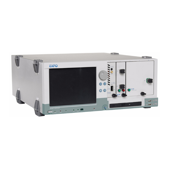
- Page 1 User Guide IQS-1600 High Speed Power Meter for IQS Platforms...
- Page 2 Engineering Inc. (EXFO). Information provided by EXFO is believed to be accurate and reliable. However, no responsibility is assumed by EXFO for its use nor for any infringements of patents or other rights of third parties that may result from its use.
-
Page 3: Table Of Contents
Contents Contents Certification Information ....................... vi 1 Introducing the IQS-1600 High Speed Power Meter ........1 Main Features .........................1 Typical Applications ........................4 Conventions ..........................5 2 Safety Information ..................7 3 Getting Started with Your High Speed Power Meter ......... 9 Inserting and Removing Test Modules ..................9 Starting the High Speed Power Meter Application ..............14 Entering Values Using Sliders and Numeric Boxes ..............17... - Page 4 Recalibrating the Unit ......................107 Recycling and Disposal (Applies to European Union Only) ..........108 14 Troubleshooting ..................109 Solving Common Problems ....................109 Viewing Online Documentation ..................111 Finding Information on the EXFO Web Site ................112 Contacting the Technical Support Group ................113 Transportation ........................114 IQS-1600...
- Page 5 General Information ......................115 Liability ..........................115 Exclusions ...........................116 Certification ........................116 Service and Repairs ......................117 EXFO Service Centers Worldwide ..................118 A Technical Specifications ................119 B SCPI Command Reference ............... 121 Quick Reference Command Tree ..................122 Product-Specific Commands—Description ................126 Index ......................225...
-
Page 6: Certification Information
F.C.C. Information Electronic test equipment is exempt from Part 15 compliance (FCC) in the United States. However, compliance verification tests are systematically performed on most EXFO equipment. Information Electronic test equipment is subject to the EMC Directive in the European Union. - Page 7 DECLARATION OF CONFORMITY Application of Council Directive(s): 73/23/EEC - The Low Voltage Directive 89/336/EEC - The EMC Directive And their amendments Manufacturer’s Name: EXFO Electro-Optical Engineering Inc. Manufacturer’s Address: 400 Godin Avenue Quebec, Quebec Canada G1M 2K2 (418) 683-0211 Equipment Type/Environment: Test &...
-
Page 9: Introducing The Iqs-1600 High Speed Power Meter
Introducing the IQS-1600 High Speed Power Meter Designed for the IQS platforms, the IQS-1600 High Speed Power Meter is a module available in three different models. It is used with the OHS-1700 Optical Head. Main Features The IQS-1600 High Speed Power Meter is offered in different configurations: Standard option—IQS-1600 Series Low-PDL option—IQS-1600-PL Series... - Page 10 The IQS-1600 High Speed Power Meter supports local control (via the IQS Manager software) and remote control (through GPIB, RS-232, or Ethernet TCP/IP using SCPI commands or the provided LabVIEW drivers). For more information, refer to the IQS platform user guide. IQS-1600...
- Page 11 Introducing the IQS-1600 High Speed Power Meter Main Features Moreover, a special model was designed for the IQS-12004B DWDM Passive Component Test System The IQS-1643T-PL-SN presents specifications that are very close to the IQS-1643-PL-SN standalone module. Every customer purchasing the IQS-12004B system for applications covering both the C- and L-bands will receive an IQS-1643T-PL-SN.
-
Page 12: Typical Applications
Introducing the IQS-1600 High Speed Power Meter Typical Applications Typical Applications Your power meter is suitable for numerous applications, including the following: Insertion loss of passive components in the production environment Component and system monitoring Source stability characterization Absolute power measurements Manual or automated splice loss measurement Characterization of MUX/DEMUX, used in conjuction with a tunable laser source, or within the IQS-12004B DWDM Passive Component Test... -
Page 13: Conventions
Introducing the IQS-1600 High Speed Power Meter Conventions Conventions Before using the product described in this manual, you should understand the following conventions: ARNING Indicates a potentially hazardous situation which, if not avoided, could result in death or serious injury. Do not proceed unless you understand and meet the required conditions. -
Page 15: Safety Information
Safety Information Your power meter does not contain laser components in itself. However, you will be using it with light sources. ARNING Do not install or terminate fibers while a light source is active. Never look directly into a live fiber and ensure that your eyes are protected at all times. -
Page 17: Getting Started With Your High Speed Power Meter
Getting Started with Your High Speed Power Meter This chapter contains information on how to insert and remove test modules. You will also find how to connect your optical head to your power meter and how to start and exit the application. Inserting and Removing Test Modules AUTION Never insert or remove a module while the controller unit and its... - Page 18 Getting Started with Your High Speed Power Meter Inserting and Removing Test Modules 3. Position the module so that its front panel is facing you and the top and bottom protruding edges are to your right. 4. Insert the protruding edges of the module into the grooves of the unit’s module slot.
- Page 19 Getting Started with Your High Speed Power Meter Inserting and Removing Test Modules The module is correctly inserted when its front panel is flush with the front panel of the controller or expansion unit. When you turn on the controller unit, the startup sequence will automatically detect your module.
- Page 20 Getting Started with Your High Speed Power Meter Inserting and Removing Test Modules 2. Place your fingers underneath the module or hold it by the retaining screw knob (NOT by the connector) and pull it out. Connector Retaining screw knob AUTION Pulling out a module by a connector could seriously damage both the module and connector.
- Page 21 Getting Started with Your High Speed Power Meter Inserting and Removing Test Modules AUTION Failure to reinstall protective covers over empty slots will result in ventilation problems. High Speed Power Meter...
-
Page 22: Starting The High Speed Power Meter Application
Your IQS-1600 High Speed Power Meter module can be configured and controlled from its dedicated IQS Manager application. Note: For details about IQS Manager, refer to the IQS platform user guide. To start the application: 1. From the Current Modules function tab select the module to use. - Page 23 Getting Started with Your High Speed Power Meter Starting the High Speed Power Meter Application Title bar Data display Function buttons Parameter definition controls Status bar High Speed Power Meter...
- Page 24 Remote: Module controlled remotely, but local commands can also be used. Lockout: Module controlled remotely only. Module/unit status Current date and time For more information about automating or remotely controlling the IQS-1600 High Speed Power Meter, refer to your platform user guide. IQS-1600...
-
Page 25: Entering Values Using Sliders And Numeric Boxes
Getting Started with Your High Speed Power Meter Entering Values Using Sliders and Numeric Boxes Entering Values Using Sliders and Numeric Boxes Many parameters in IQS Manager and module applications can be set using the following tools. Slider Fine-tuning Numeric box button Navigation buttons Slider: Drag it to the desired value on the scale below. -
Page 26: Exiting The Application
Getting Started with Your High Speed Power Meter Exiting the Application Exiting the Application Closing any application that is not currently being used is a good way to free system memory. To close the application from the main window: Click in the top right corner of the main window. -
Page 27: Setting Up Your High Speed Power Meter
Setting Up Your High Speed Power Meter You can set the following paameters on your IQS-1600: Chanel display Wavelength selection and management Measurement unit selection Display resolution Refresh rate Measurement range Saving and recalling configuration High Speed Power Meter... -
Page 28: Setting Channel Display(Iqs-1620, Iqs-1640)
Setting Up Your High Speed Power Meter Setting Channel Display(IQS-1620, IQS-1640) Setting Channel Display(IQS-1620, IQS-1640) The channel display allows you to select which channels you want to view when using a multichannel power meter. You can display up to three optical channels using a dual-channel power meter (the two normal channels, plus the virtual channel) and up to four optical channels using a four-channel power meter. - Page 29 Setting Up Your High Speed Power Meter Setting Channel Display(IQS-1620, IQS-1640) Selecting a Channel (IQS-1620, IQS-1640) The IQS-1620 and IQS-1640 have two and four independent optical channels respectively. To select an optical channel: From the Instrument function tab, go to Channel and use the arrow buttons next to the channel number to change it.
- Page 30 Setting Up Your High Speed Power Meter Setting Channel Display(IQS-1620, IQS-1640) Selecting a Virtual Channel (IQS-1620, IQS-1640) In addition to the optical channels, your application offers one virtual channel for the dual-channel power meter and two virtual channels for the quadruple-channel power meter.
- Page 31 Setting Up Your High Speed Power Meter Setting Channel Display(IQS-1620, IQS-1640) To define a virtual channel: 1. Click on the Settings function tab, then select the Virtual Channels tab. 2. Click on the desired virtual channel (when using a dual-channel power meter, only virtual channel 1 is available).
- Page 32 Setting Up Your High Speed Power Meter Setting Channel Display(IQS-1620, IQS-1640) Since operations between channels cannot be made with any type of measurement unit, the second channel and the operator can be selected according to the unit of the first channel as described in the following table. First Second Virtual Channel Unit and...
- Page 33 Setting Up Your High Speed Power Meter Setting Channel Display(IQS-1620, IQS-1640) Naming Channels A user-selected name can be given to each power meter channel, including virtual channels. The channel name appears in the main window. Naming individual channels is particularly useful when you need to display more than one power channel at the same time, especially in Monitor Window mode with several optical power meters displayed simultaneously.
-
Page 34: Selecting The Wavelength
Setting Up Your High Speed Power Meter Selecting the Wavelength Selecting the Wavelength When taking accurate measurements, your power meter must be set to the correct wavelength to compensate for the photodetector responsivity at the incident wavelength. Ideally, the power meter’s wavelength should be set as close as possible to that of the optical source being used. -
Page 35: Managing Wavelength Lists
Setting Up Your High Speed Power Meter Managing Wavelength Lists Managing Wavelength Lists The wavelengths you want to use with your IQS-1600 and OHS-1700 must be entered in the Wavelength list. Please refer to the Certificate of Compliance supplied with your power meter for information on the wavelength range. -
Page 36: Selecting The Measurement Unit
Setting Up Your High Speed Power Meter Selecting the Measurement Unit Selecting the Measurement Unit Power measurements can be displayed in dB, dBm, W, or W/W (the latter indicating the ratio between the power received and the reference for the current wavelength and channel). -
Page 37: Setting The Display Resolution
Setting Up Your High Speed Power Meter Setting the Display Resolution Setting the Display Resolution Depending on the required resolution and operating power level, 0, 1, 2, 3, or 4 digits can be displayed after the decimal point. When the auto setting is selected, the display resolution is determined by the power level being measured. - Page 38 Setting Up Your High Speed Power Meter Setting the Display Resolution 2. Use the arrow buttons to select the value in the Display Res. list. If you have previously selected watts as units, the Display Res. list will be grayed out. 3.
-
Page 39: Setting The Refresh Rate
Setting Up Your High Speed Power Meter Setting the Refresh Rate Setting the Refresh Rate This function allows you to define the refresh rate of the power readings on the display. The refresh rate is the number of times per second that a new power measurement will be displayed on the screen. -
Page 40: Setting The Measurement Range
Setting Up Your High Speed Power Meter Setting the Measurement Range Setting the Measurement Range The measurement range and gain scale applied to the power detector can be manually selected to prevent the automatic scale adjustment performed by the instrument. A manual adjustment of the dynamic gain scale will lock the measurement range to a specific level. - Page 41 Setting Up Your High Speed Power Meter Setting the Measurement Range To set the measurement range: 1. Click the Settings function tab, then select the Channels tab. 2. If necessary, select the channel for which you want to set the range. 3.
- Page 42 Setting Up Your High Speed Power Meter Setting the Measurement Range 4. Use the arrow buttons next to the Scale list and highlight the scale you wish to use. The table on the following page displays the permitted scales when the currently selected measurement unit is dB or dBm.
-
Page 43: Saving And Recalling Configurations
Setting Up Your High Speed Power Meter Saving and Recalling Configurations Saving and Recalling Configurations Once you have set the IQS-1600 High Speed Power Meter parameters, you can save your custom configuration and recall it at any time. You can also recall the factory-defined settings. - Page 44 Setting Up Your High Speed Power Meter Saving and Recalling Configurations To recall a configuration: 1. Select the Configuration function tab. 2. Click Open. 3. Select the configuration file you wish to recall and confirm your action. You are returned to the application and the new parameters are set. To revert to factory settings: 1.
-
Page 45: Preparing Your High Speed Power Meter For A Test
To ensure maximum power and to avoid erroneous readings: Always clean fiber ends as explained below before inserting them into the port. EXFO is not responsible for damage or errors caused by bad fiber cleaning or handling. Ensure that your patchcord has appropriate connectors. Joining mismatched connectors will damage the ferrules. -
Page 46: Nulling Offsets
Preparing Your High Speed Power Meter for a Test Nulling Offsets Nulling Offsets Temperature and humidity variations affect the performance of electronic circuits and optical detectors, which can offset measurement results. To compensate for this offset, the unit is equipped with an offset nulling function. - Page 47 Preparing Your High Speed Power Meter for a Test Nulling Offsets To perform an offset nulling on one channel: 1. Install the protective cap over the detector port. 2. If necessary, select the desired channel (on a multichannel high-speed power meter). To set the channel, see Selecting a Channel (IQS-1620, IQS-1640) on page 21.
- Page 48 Preparing Your High Speed Power Meter for a Test Nulling Offsets To perform an offset nulling on all channels (two- and four-channel power meters): 1. Install the protective caps over all of the detector ports. 2. Under Nulling, click the All Channels button. Offset nulling values are applied to the channel until a new nulling is performed.
-
Page 49: Measuring Power
Measuring Power Power measurements can be displayed in two ways: absolute relative It is also possible to use a correction factor at specific wavelengths and to add an offset value to your power measurement. Displaying Absolute Power When in absolute power, measured values are displayed in either dBm or W units (pW, nW, μW, mW...) and the displayed value represents the absolute optical power reaching the detector within specified uncertainty. - Page 50 Measuring Power Displaying Absolute Power To display absolute power: 1. Select the Instrument function tab or the Channels tab of the Settings function tab (you can use either). 2. Select the channel for which you want to set the offset if you are using a multichannel power meter.
-
Page 51: Measuring Relative Power
Measuring Power Measuring Relative Power Measuring Relative Power Power measurements can be displayed as a deviation from an absolute reference value. The relative power is particularly useful when performing loss measurements. Relative power is displayed in dB when the reference value is measured in dBm. -
Page 52: Selecting The Reference Value
Measuring Power Selecting the Reference Value Selecting the Reference Value The reference value influences your measurements once selected and activated. Whether you select the current module’s power or a set value from the list, this becomes the basis for your future acquisitions. To select the reference value: 1. -
Page 53: Editing The Reference List
Measuring Power Editing the Reference List Editing the Reference List The Reference list can be changed to adapt to your testing requirements. To add a reference to the list: 1. From the Settings function tab, select the Lists tab. 2. Under Reference List, enter the name of the new reference value in the Name box. -
Page 54: Measuring Corrected Power
Measuring Power Measuring Corrected Power To delete a user reference from the list: 1. From the Settings function tab, select the Lists tab. 2. Select the value to remove by clicking it once. 3. Click to remove the value. Measuring Corrected Power Applying a correction factor to the measured power is useful when compensating for known inaccuracies (power gains or losses) at specific wavelengths. - Page 55 Measuring Power Measuring Corrected Power To set a correction factor: 1. From the Settings function tab, select the Channels tab. 2. Select the channel for which you want to set the CF (in the case of a two- or four-channel power meter). 3.
-
Page 56: Using The Offset Function
Measuring Power Using the Offset Function Using the Offset Function The offset function is used when you want to take into account, in the power displayed, a known gain or loss in the link that is not already included in the signal reaching the detector.Contrary to the correction factor, which applies to a specific wavelength, the offset value applies to any wavelength when it is enabled in a specific channel. -
Page 57: Averaging Measurements
Measuring Power Averaging Measurements Averaging Measurements When the averaging function is enabledIQS-1600 High Speed Power Meter, the most recent measurement samples, for which you can set the number, are used to compute an unweighted average. This average is displayed as the measured value. - Page 58 Measuring Power Averaging Measurements If you are setting the average value in the Instrument function tab, you must first press the Averaging button to activate the list. Average /Averaging lists To toggle between averaged and unaveraged power measurement: 1. If necessary, select the desired channel from the Instrument function tab.
-
Page 59: Recording Power Signal Variations
Recording Power Signal Variations The Min./Max. function allows you to record the extremes of a varying power signal when performing a continuous acquisition. For example, it could be used to determine the stability of a light source over time or to measure the polarization-dependent loss (PDL) of a passive component when combined with a polarization state controller. - Page 60 Recording Power Signal Variations 2. Select the channel for which you want to see the power variation data on-screen by clicking the corresponding buttons in the Min./Max. tab. In the case of dual-channel power meters, you can select up to three channels (the two normal channels, plus the virtual channel) and in the case of the four-channel power meter, you can select up to six channels, including the virtual channels.
- Page 61 Recording Power Signal Variations These can be stopped at any time by clicking Stop. If the timer is set, power measurements will stop automatically after the specified duration. Note: The remaining duration is indicated under the Start and Stop button. The Reset button will reinitialize the Min./Max.
-
Page 63: Performing Acquisitions
Performing Acquisitions You can perform your acquisition on one or several channels at the same time (in the case of multichannel power meters). To select which channel will be affected by your acquisition: 1. From the Settings function tab, select the Data Acquisition tab. 2. -
Page 64: Selecting The Sampling Type
Performing Acquisitions Selecting the Sampling Type Selecting the Sampling Type You can perform different types of samplings with your power meter: Continuous sampling signifies that power measurements are constantly updated on the measurement display for an unlimited time period. You can select a rate that will optimize instrument flexibility and measurement stability as well as determine the quantity of data generated during data acquisition. - Page 65 Performing Acquisitions Selecting the Sampling Type To select a sampling type: 1. From the Settings function tab, select the Data Acquisition tab. 2. Select the sampling type by clicking the corresponding button. If you select Continuous, select the rate to use with the arrow buttons. The acquisition rate applies to all channels when using a multichannel power meter.
- Page 66 Performing Acquisitions Selecting the Sampling Type You can also change the continuous sampling rate in the Instrument function tab in the same manner. If you select Single, select the rate to use with the arrow buttons. The acquisition rate applies to all channels when using a multichannel power meter.
-
Page 67: Selecting The Acquisition Mode
Performing Acquisitions Selecting the Acquisition Mode Selecting the Acquisition Mode You can use three data acquisition modes, regardless of the type of acquisition you are performing. Timer: the acquisition will last for the length of time you have previously set. Trigger: the power meter will wait for an incoming trigger signal before starting its next acquisition. - Page 68 Performing Acquisitions Selecting the Acquisition Mode To select the acquisition mode: 1. From the Settings function tab, select the Data Acquisition tab. 2. From Mode, select the desired mode or combination of modes. IQS-1600...
- Page 69 Performing Acquisitions Selecting the Acquisition Mode Setting Up Timed Acquisition Duration A timed acquisition starts when you start the process, and continues for the time you have previously specified. To set the duration for your acquisition: Click inside the Timer edit box of the Data Acquisition tab and enter the value (or use the arrow buttons next to the list to adjust it).
- Page 70 Performing Acquisitions Selecting the Acquisition Mode Setting Up Delayed Acquisition Delay Delayed acquisition starts at a specified time after you start the process, and continues for the time you have previously specified if you have selected a combination of Timed and Delayed acquisition types. To set a delay for your acquisition: 1.
- Page 71 Performing Acquisitions Selecting the Acquisition Mode Setting Trigger Acquisition Parameters Conditional data acquisition can be performed using a triggered acquisition, meaning that data recording begins when a specified condition is met. Different trigger conditions are available, which are explained in the following table, where A and/or B represent the channel on which the condition is to be met, and x and/or y represent the desired power level threshold.
- Page 72 Performing Acquisitions Selecting the Acquisition Mode Note: The trigger defines the condition for starting data acquisition. Once begun, acquisitions will continue for the specified duration, regardless of the measured power. To set up the power level trigger condition: 1. From Trigger of the Data Acquisition tab, use the arrow buttons next to the Type list to select the desired condition.
- Page 73 Performing Acquisitions Selecting the Acquisition Mode Note: The X and Y values are displayed in the currently selected unit. 3. Enter the appropriate X or Y values in the corresponding lists. 4. Click to confirm your setting. If you select a Single acquisition rate, the External Trigger switch and Trigger Position (%) options become available.
-
Page 74: Starting The Acquisition
Performing Acquisitions Starting the Acquisition Starting the Acquisition Once you have set your parameters, you can start the acquisition. To start an acquisition: 1. Select the Instrument function tab. 2. From the Acquisition tab, press Start. Data acquisition can be terminated at any time by clicking Stop. The accumulated data is available in the data file. - Page 75 Performing Acquisitions Starting the Acquisition You can also start the acquisition in the Graph tab by clicking the Start button the same way you would in the Control tab. MPORTANT If you change units on one or more channels using Relative or Absolute mode and that you had enabled Graph mode, the Graph and Start buttons might automatically disable themselves if the resulting changes are not compatible with the base unit used in the...
-
Page 76: Consulting Acquired Data
Performing Acquisitions Consulting Acquired Data Consulting Acquired Data Once you have acquired data, it is possible to view the results in IQS Manager. To view data previously acquired: 1. In IQS Manager, select the Work on Results (Offline) function tab. 2. - Page 77 Performing Acquisitions Consulting Acquired Data 3. In the viewer, retrieve the corresponding file using the button. To view the details pertaining to the channels used for the acquisition, select the General tab. High Speed Power Meter...
- Page 78 Performing Acquisitions Consulting Acquired Data To view your acquisition data, select the Data tab. IQS-1600...
- Page 79 Performing Acquisitions Consulting Acquired Data To view the graph corresponding to your acquisition data, select the Graph tab. To move along the time scale, use the arrow buttons. The single arrow buttons will move by increments or decrements representing 10 % of the current trace scale value. The double arrow buttons will move by increments or decrements of the current screen display (for example, the 10 to 40 seconds display would become 40 to 70 seconds in the figure...
- Page 80 Performing Acquisitions Consulting Acquired Data If you want to save your acquisition file as a text file, use the Export button located on the upper right-hand corner of the window. Save the file as you would any other text file, then confirm your choice. You can now view your data in any word processing program.
-
Page 81: Performing And Analyzing Graph Acquisitions
Performing and Analyzing Graph Acquisitions The Graph mode of your power meter allows you to view your acquisition as it is performed, and analyze it once it has been completed. Setting Up Graph Parameters Before acquiring data, you should set the parameters that will help you achieve a better viewing afterwards. - Page 82 Performing and Analyzing Graph Acquisitions Setting Up Graph Parameters Note: You can only hide or display channels actually used for this acquisition. Moreover, only channels in the type of unit selected for the acquisition (absolute or relative) will be displayed. For example, if your graph was set to dBm units before the acquisition, you will see the graphs for channels using W or dBm as the unit.
- Page 83 Performing and Analyzing Graph Acquisitions Setting Up Graph Parameters To change the base unit of the acquisition (dBm or watts): Use the arrow buttons in the Settings tab to toggle between them. If you set the base unit before performing an acquisition, you will have the choice between W, dBm, dB, and W/W.
-
Page 84: Printing Graph Results
Performing and Analyzing Graph Acquisitions Printing Graph Results Printing Graph Results Once you have acquired data and displayed a graph, it is possible to print out this information. To print your graph results: Click in the Graph Center. Use the arrow buttons to select the printer to use. You can enter a title for your document in the corresponding box. -
Page 85: Using The Zoom Function
Performing and Analyzing Graph Acquisitions Using the Zoom Function Using the Zoom Function Once you have performed an acquisition, you can use various zooming tools to help you analyze it. To access and use the zoom tools: Click the Zoom Control tab of the Graph Center. allows you to enlarge a precise portion of the trace by dragging a zone over it. - Page 86 Performing and Analyzing Graph Acquisitions Using the Zoom Function allows you to enlarge the trace display at the precise location where you click. Click the area repeatedly until you reach the desired zoom factor. allows you to reduce the trace display at the precise location where you click.
-
Page 87: Displaying And Moving Markers
Performing and Analyzing Graph Acquisitions Displaying and Moving Markers Displaying and Moving Markers Once you have acquired a trace, you can use markers to take precise measurements. To enable the markers: 1. Select the channel you want to use from the Channel pull-down list in the Markers tab. - Page 88 Performing and Analyzing Graph Acquisitions Displaying and Moving Markers Note: If you have enabled the markers and you move to another tab (than the Zoom tab), the markers will still be visible, but you cannot move them. You must return to the Markers tab to do so. You will notice that the difference between the markers (B −...
-
Page 89: Using The External Trigger And Analog Outputs
10 Using the External Trigger and Analog Outputs Both the external trigger and analog output (SMB connectors) are accessible from the front panel of your power meter module. IQS-1610 IQS-1620 IQS-1640 Analog output port ANALOG OUT ANALOG OUT EXT. TRIG Sync IQS-1600 EXT. -
Page 90: External Trigger
Using the External Trigger and Analog Outputs External Trigger External Trigger The external trigger is used to synchronize or stimulate the acquisition of power measurements with an electrical signal (TTL level). Single acquisitions of up to 4096 Hz can be performed. The external trigger can only be used with a Single acquisition rate. -
Page 91: Analog Output (Iqs-1610, Iqs-1620)
Using the External Trigger and Analog Outputs Analog Output (IQS-1610, IQS-1620) Connecting a TTL Source to the External Trigger A synchronizing signal from a signal generator or from a control circuit may be connected to the external trigger input of the your high-speed power meter module if it does not exceed TTL levels. - Page 92 Using the External Trigger and Analog Outputs Analog Output (IQS-1610, IQS-1620) The following is an illustration of typical uses of the analog output. Analog output IQS-1600 Digital oscilloscope ANALOG OUT EXT. TRIG IQS-1600 2-Ch Power Meter Analog output Data logger IQS-1600 ANALOG OUT EXT.
- Page 93 Using the External Trigger and Analog Outputs Analog Output (IQS-1610, IQS-1620) When using your high-speed power meter with rising optical power, saturation of the scale converter will be reached when +++++++ is displayed. At that moment, the voltage in the analog output will be 2.15 V. Even with +++++++ displayed, the optical power can still be increased further and the analog output will continue to increase proportionately.
- Page 94 Using the External Trigger and Analog Outputs Analog Output (IQS-1610, IQS-1620) 2. Select the Analog Out tab. 3. Select an analog output in Settings (Analog Out 1 for a one- or four-channel power meter, or Analog Out 1 or 2 for a two-channel power meter) by clicking the corresponding button.
-
Page 95: Monitoring Power Meter Modules
Monitor windows display basic data about modules. A combination of resizable windows allows you to create an integrated data display (refer to the platform user guide). From the monitor window, you can change module parameters either by: opening the module application to access all the functions using the QuickTools utility, which provides frequently used functions from the application. - Page 96 Monitoring Power Meter Modules Using Monitor Windows To select modules and display their monitor windows: 1. On the Current Modules function tab, select the controller or expansion unit containing the modules you want to monitor. Selected modules (checked) 2. In the Monitor column, select the box next to each module you want to monitor.
- Page 97 Monitoring Power Meter Modules Using Monitor Windows 3. Click Start Monitor to apply your selection. IQS Manager will display the selected monitor windows on the Monitors function tab. Note: To start the highlighted module’s corresponding application at the same time, click Start App. & Monitor. The application will appear in a different window.
-
Page 98: Using Quicktools
Monitoring Power Meter Modules Using QuickTools Using QuickTools With QuickTools, you can fine-tune your module directly, while keeping an eye on your entire test setup. Note: You can only access QuickTools if the module’s monitor window is selected from the Monitors function tab and is currently active. To start QuickTools: 1. - Page 99 Monitoring Power Meter Modules Using QuickTools To close QuickTools: Click the Close button located at the top of the window. Click outside the QuickTools window. To close a monitor window: Click the button on the upper left of the monitor window and select Remove Monitor.
-
Page 101: 12 Typical Applications
12 Typical Applications For accurate, significant, and repeatable power measurements, it is important to consider the following points: Connectors, fiber ends, ports, and detectors should be clean at all times. A null measurement should be performed prior to each user session or whenever there is a significant change in ambient temperature or environmental conditions. -
Page 102: Performing Absolute Power Measurements
Typical Applications Performing Absolute Power Measurements Performing Absolute Power Measurements Absolute power measurements are necessary when performing system or component monitoring, quality control, system or component acceptance, and troubleshooting. To carry out absolute power measurements: 1. Perform an offset nulling as explained in Nulling Offsets on page 38. 2. - Page 103 Typical Applications Performing Absolute Power Measurements Note: The high-speed power meter virtual channel (IQS-1620 or IQS-1640) is an excellent tool for comparing two optical channels. For example, if two devices (connected to channels 1 and 2) are supposed to have identical power levels, displaying a virtual channel (defined as channel 1 minus channel 2) provides easy monitoring of both devices and will quickly highlight any power fluctuations.
-
Page 104: Measuring Insertion Loss
Measuring Insertion Loss Measuring Insertion Loss To accurately measure the insertion loss of a fiber-optic component, use a light source (such as EXFO’s IQS-2100 Light Source) and your high-speed power meter. To measure the insertion loss: 1. Perform an offset nulling of the detector(s) if needed. - Page 105 Typical Applications Measuring Insertion Loss MPORTANT The absolute power output value is not particularly important when measuring insertion loss. It is very important, however, that the power level used for taking the reference measurement is identical to the power level used during the insertion loss measurement. 6.
-
Page 106: Testing Instrument Linearity
When verifying instrument linearity, a linear variable attenuator (such as EXFO’s IQS-3100 Variable Attenuator) is also required. Before verifying the linearity of an optical detector, you must confirm the linearity of the attenuator being used. - Page 107 Typical Applications Testing Instrument Linearity To confirm the linearity of the attenuator being used, you need a stable source (IQS-2100), a variable attenuator, your high-speed power meter, two test jumpers, and appropriate connector adapters. Once you are confident with both the test setup and instruments being used, you can start testing for component linearity.
-
Page 108: Characterizing An Optical Switch
Typical Applications Characterizing an Optical Switch 6. At this time, both the attenuator and power meter will display “0.0 dB”. Increase the attenuation using constant step sizes, while recording the values from both displays (attenuator and power meter) at each step. Continue until the power meter indicates around −55 dB. - Page 109 Typical Applications Characterizing an Optical Switch Testing Repeatability The procedure to test the repeatability of an optical switch is relatively simple. First, a reference measurement must be taken on each channel. Next, repetitive transitions of the switch must be performed. The switch repeatability will be the total deviation from the reference points.
- Page 110 Typical Applications Characterizing an Optical Switch 7. Set the switch to the first position and take a reference measurement on the channel receiving the signal. 8. Set the switch to the second position and take a reference measurement on the second channel, now receiving the signal. 9.
-
Page 111: 13 Maintenance
13 Maintenance To help ensure long, trouble-free operation: Always clean fiber-optic connectors before using them. Keep the unit free of dust. Clean the unit casing and front panel with a cloth slightly dampened with water. Store unit at room temperature in a clean and dry area. Keep the unit out of direct sunlight. -
Page 112: Cleaning Fixed Connectors
Maintenance Cleaning Fixed Connectors Cleaning Fixed Connectors Regular cleaning of connectors will help maintain optimum performance. Do not try to disassemble the unit. Doing so would break the connector. To clean fixed connectors: 1. Fold a lint-free wiping cloth in four to form a square. 2. - Page 113 9. Continue to turn as you withdraw the cleaning tip. 10. Repeat steps 7 to 9, but this time with a dry cleaning tip (2.5 mm tip provided by EXFO). Note: Make sure you don’t touch the soft end of the cleaning tip and verify the cleanliness of the cotton tip.
-
Page 114: Cleaning Detector Ports
Maintenance Cleaning Detector Ports Cleaning Detector Ports Regular cleaning of detectors will help maintain measurement accuracy. MPORTANT Always cover detectors with protective caps when unit is not in use. To clean detector ports: 1. Remove the protective cap and adapter (FOA) from the detector. 2. -
Page 115: Cleaning The Analog Output And External Trigger Ports
You should determine the adequate calibration interval for your unit according to your accuracy requirements. Under normal use, EXFO recommends calibrating your unit every year. High Speed Power Meter... -
Page 116: Recycling And Disposal (Applies To European Union Only)
This equipment was sold after August 13, 2005 (as identified by the black rectangle). Unless otherwise noted in a separate agreement between EXFO and a customer, distributor or commercial partner, EXFO will cover costs related to the collection, treatment, recovery and disposal of... -
Page 117: 14 Troubleshooting
System units, then remove and reinsert the module. Unit has locked up. Reboot the Intelligent Test System. LED is burnt out. Call EXFO. Pressing LED push Computer has Reboot the Intelligent Test button does not locked up. System. - Page 118 Troubleshooting Solving Common Problems Problem Probable Cause Recommended Action * * * * * * * is Channel not Click the Active button for displayed as power active. the appropriate channel in value. the Channel tab of the Channel not Settings function tab.
-
Page 119: Viewing Online Documentation
Troubleshooting Viewing Online Documentation Viewing Online Documentation An online version of the IQS-1600 High Speed Power Meter user guide is conveniently available at all times from the application. To access the online user guide: Click Help in the function bar. -
Page 120: Finding Information On The Exfo Web Site
Troubleshooting Finding Information on the EXFO Web Site Finding Information on the EXFO Web Site The EXFO Web site provides answers to frequently asked questions (FAQs) regarding the use of your IQS-1600 High Speed Power Meter. To access FAQs: 1. Type http://www.exfo.com... -
Page 121: Contacting The Technical Support Group
Contacting the Technical Support Group To obtain after-sales service or technical support for this product, contact EXFO at one of the following numbers. The Technical Support Group is available to take your calls from Monday to Friday, 8:00 a.m. to 7:00 p.m. -
Page 122: Transportation
Troubleshooting Transportation Transportation Maintain a temperature range within specifications when transporting the unit. Transportation damage can occur from improper handling. The following steps are recommended to minimize the possibility of damage: Pack the unit in its original packing material when shipping. Avoid high humidity or large temperature fluctuations. -
Page 123: 15 Warranty
SPECIAL, INCIDENTAL, OR CONSEQUENTIAL DAMAGES. Liability EXFO shall not be liable for damages resulting from the use of the product, nor shall be responsible for any failure in the performance of other items to which the product is connected or the operation of any system of which the product may be a part. -
Page 124: Exclusions
Warranty Exclusions Exclusions EXFO reserves the right to make changes in the design or construction of any of its products at any time without incurring obligation to make any changes whatsoever on units purchased. Accessories, including but not limited to fuses, pilot lamps, batteries and universal interfaces (EUI) used with EXFO products are not covered by this warranty. -
Page 125: Service And Repairs
5. Return the equipment, prepaid, to the address given to you by support personnel. Be sure to write the RMA number on the shipping slip. EXFO will refuse and return any package that does not bear an RMAnumber. -
Page 126: Exfo Service Centers Worldwide
Warranty EXFO Service Centers Worldwide EXFO Service Centers Worldwide If your product requires servicing, contact your nearest authorized service center. EXFO Headquarters Service Center 400 Godin Avenue 1 866 683-0155 (USA and Canada) Quebec (Quebec) G1M 2K2 Tel.: 1 418 683-5498... -
Page 127: A Technical Specifications
MPORTANT The following technical specifications can change without notice. The information presented in this section is provided as a reference only. To obtain this product’s most recent technical specifications, visit the EXFO Web site at www.exfo.com. SPECIFICATIONS (IQS-1600 Series) Model... - Page 128 Technical Specifications GENERAL SPECIFICATIONS IQS-1710/1720 IQS-1613/1623/1643 IQS-1613W/1623W/1643W IQS-1712X/1722X OHS-1713W-PL OHS-1713-UH External trigger input voltage (V) 0 to 5 (TTL) 0 to 5 (TTL) Size (H x W x D) 125 mm x 36 mm x 282 mm 125 mm x 36 mm x 282 mm 125 mm x 36 mm x 282 mm 43 mm x 66 mm x 151 mm 42 mm x 79 mm x 190 mm...
-
Page 129: B Scpi Command Reference
<LogicalInstrumentPos> corresponds to the identification number of the instrument. IQS controller or expansion unit identification number (for example, 001) XXXY Instrument slot number (0 to 9) For information on modifying unit identification, refer to your platform user guide. High Speed Power Meter... -
Page 130: Quick Reference Command Tree
SCPI Command Reference Quick Reference Command Tree Quick Reference Command Tree Command Parameter(s) ABORt[1..n] FETCh[1..n] [SCALar] POWer FORMat[1..n] [DATA] <FormatData> [DATA]? INITiate[1..n] [IMMediate] AUTO <StartStop>,CONT|NCONt AUTO? CONTinuous <ContinuousAcquisition> CONTinuous? EXTRema <Extrema> EXTRema? MEASure[1..n] [SCALar] POWer MAXimum? MINimum? MMEMory[1..n] ACQuisition <StartStop>,CONT|NCONt ACQuisition? ACQuisition DURation... - Page 131 SCPI Command Reference Quick Reference Command Tree Command Parameter(s) FNAMe <FileName> FNAMe? READ[1..n] [SCALar] POWer SENSe[1..n] AVERage [STATe] <AverageState> [STATe]? COUNt <AverageCount>|MAXimum|MINi mum|DEFault COUNt? [MINimum|MAXimum|DEFault] CORRection COLLect ZERO ASYNchronous FACTor [MAGNitude] <CorrectionFactor[<wsp>W/W|D B]>|MAXimum|MINimum|DEFault [MAGNitude]? [MINimum|MAXimum|DEFault] OFFSet [MAGNitude] <CorrectionOffset[<wsp>W/W|DB ]>|MAXimum|MINimum|DEFault [MAGNitude]? [MINimum|MAXimum|DEFault] FREQuency CONTinuous...
- Page 132 SCPI Command Reference Quick Reference Command Tree Command Parameter(s) POWer [DC] RANGe AUTO <AutoRangeState> AUTO? HIGH <HighRange> LOWer <LowRange> SCALe? [MINimum|MAXimum|DEFault] SCALe LIST? REFerence <Reference[<wsp>W|DBM]>|MA Ximum|MINimum|DEFault REFerence? [MINimum|MAXimum|DEFault] REFerence DISPlay STATe <ReferenceState> STATe? UNIT DBM|W UNIT? WAVelength <Wavelength>|MAXimum|MINimu m|DEFault WAVelength? [MINimum|MAXimum|DEFault] SLINstrument CATalog?
- Page 133 SCPI Command Reference Quick Reference Command Tree Command Parameter(s) MAX? TRC1|TRC2|TRC3|TRC4 MIN? TRC1|TRC2|TRC3|TRC4 POINts TRC1|TRC2|TRC3|TRC4[,<Number Point>] POINts? TRC1|TRC2|TRC3|TRC4 TRIGger[1..n] POSition <TriggerPosition> POSition? POSition CATalog? [SEQuence] LEVel <TriggerPowerLevel> LEVel? SLOPe NEGative|POSitive SLOPe? SOURce EXTernal|INTernal1|INTernal2|INTe rnal3|INTernal4|INTernal5|INTernal SOURce? STATe <TriggerState> STATe? UNIT[1..n] POWer DB|DBM|W|W/W|WATT|WATT/W POWer? High Speed Power Meter...
-
Page 134: Product-Specific Commands-Description
SCPI Command Reference Product-Specific Commands—Description Product-Specific Commands—Description :ABORt[1..n] Description This command is used to stop the acquisition currently in progress. Syntax :ABORt[1..n] Parameter(s) None Example(s) INIT:CONT ON ABOR See Also INITiate:AUTO INITiate:AUTO? INITiate:CONTinuous INITiate:CONTinuous? INITiate:EXTRema INITiate:EXTRema? INITiate:IMMediate MMEMory:ACQuisition MMEMory:ACQuisition? IQS-1600... - Page 135 SCPI Command Reference Product-Specific Commands—Description :FETCh[1..n][:SCALar]:POWer:DC? Description This query returns the stored value on the specified channel. To fetch a specific channel, enter the channel number as a suffix of the FETC keyword. The maximum channel is device-dependent. Channel 1 is always used by default. Syntax :FETCh[1..n][:SCALar]:POWer:DC? Parameter(s)
- Page 136 SCPI Command Reference Product-Specific Commands—Description :FORMat[1..n][:DATA] Description This command changes the resolution of the power value when dB or dBm is selected for the specified channel. Syntax :FORMat[1..n][:DATA]<wsp><FormatData> Parameter(s) FormatData: The program data syntax for <FormatData> is defined as a <DECIMAL NUMERIC PROGRAM DATA>...
- Page 137 SCPI Command Reference Product-Specific Commands—Description :FORMat[1..n][:DATA]? Description This query returns the resolution of the power value when dB or dBm is selected for the specified channel. Syntax :FORMat[1..n][:DATA]? Parameter(s) None Response Syntax <FormatData> Response(s) FormatData: The response data syntax for <FormatData> is defined as a <NR3 NUMERIC RESPONSE DATA>...
- Page 138 SCPI Command Reference Product-Specific Commands—Description :INITiate[1..n][:IMMediate] Description This command stores one value in the buffer for all channels. Syntax :INITiate[1..n][:IMMediate] Parameter(s) None Example(s) INIT:IMM FETC1:POW:DC? INIT FETC1:POW:DC? See Also FETCh[:SCAL]:POWer:DC? READ[:SCAL]:POWer:DC? ABORt INITiate:AUTO INITiate:CONTinuous INITiate:EXTRema MMEMory:ACQuisition IQS-1600...
- Page 139 SCPI Command Reference Product-Specific Commands—Description :INITiate[1..n]:AUTO Description This command starts or stops an acquisition using the number of points set with the TRAC:POIN command, and the sampling rate set with the SENS:FREQ[:CONT] or SENS:FREQ:NCON commands. To start an acquisition in non-continuous mode, no channel must be set to auto scale.
- Page 140 SCPI Command Reference Product-Specific Commands—Description :INITiate[1..n]:AUTO This parameter allows to set the acquisition mode: CONT set Continuous acquisition. NCON set Single acquisition. Example(s) TRAC:POIN TRC1, 5 INIT:AUTO 1, CONT INIT:AUTO 0, CONT SENS:POW:RANG:HIGH 1 SENS2:POW:RANG:HIGH 1 SENS3:POW:RANG:HIGH 1 SENS4:POW:RANG:HIGH 1 INIT:AUTO 1, NCON See Also ABORt...
- Page 141 SCPI Command Reference Product-Specific Commands—Description :INITiate[1..n]:AUTO? Description This query returns a value indicating whether a programmed (or "Autostop") acquisition is in progress. Syntax :INITiate[1..n]:AUTO? Parameter(s) None Response Syntax <AcqOnOff> Response(s) AcqOnOff: The response data syntax for <AcqOnOff> is defined as a <NR1 NUMERIC RESPONSE DATA> element.
- Page 142 SCPI Command Reference Product-Specific Commands—Description :INITiate[1..n]:CONTinuous Description Sets continuous acquisition mode and starts or stops the acquisition. Syntax :INITiate[1..n]:CONTinuous<wsp><Continuous Acquisition> Parameter(s) ContinuousAcquisition: The program data syntax for <ContinuousAcquisition> is defined as a <Boolean Program Data> element. The <ContinuousAcquisition> special forms ON and OFF are accepted on input for increased readability.
- Page 143 SCPI Command Reference Product-Specific Commands—Description :INITiate[1..n]:CONTinuous? Description This query returns a value indicating if a continuous acquisition is in progress. Syntax :INITiate[1..n]:CONTinuous? Parameter(s) None Response Syntax <ContinuousAcqState> Response(s) ContinuousAcqState: The response data syntax for <ContinuousAcqState> is defined as a <NR1 NUMERIC RESPONSE DATA>...
- Page 144 SCPI Command Reference Product-Specific Commands—Description :INITiate[1..n]:EXTRema Description This command starts or stops the Min./Max. power measurements in Continuous acquisition mode for all channels. Syntax :INITiate[1..n]:EXTRema<wsp><Extrema> Parameter(s) Extrema: The program data syntax for <Extrema> is defined as a <Boolean Program Data> element. The <Extrema>...
- Page 145 SCPI Command Reference Product-Specific Commands—Description :INITiate[1..n]:EXTRema? Description This query returns a value indicating whether Min./Max. power measurements are in progress in Continuous acquisition mode. Syntax :INITiate[1..n]:EXTRema? Parameter(s) None Response Syntax <ExtremaOnOFF> Response(s) ExtremaOnOFF: The response data syntax for <ExtremaOnOFF> is defined as a <NR1 NUMERIC RESPONSE DATA>...
- Page 146 SCPI Command Reference Product-Specific Commands—Description :MEASure[1..n][:SCALar]:POWer: MAXimum? Description This query returns the maximum power measurement value recorded for a channel in Continuous acquisition mode. Syntax :MEASure[1..n][:SCALar]:POWer:MAXimum? Parameter(s) None Response Syntax <MaxPower> Response(s) MaxPower: The response data syntax for <MaxPower> is defined as a <NR3 NUMERIC RESPONSE DATA>...
- Page 147 SCPI Command Reference Product-Specific Commands—Description :MEASure[1..n][:SCALar]:POWer: MINimum? Description This query returns the minimum power measurement value recorded for a channel in Continuous acquisition mode. Syntax :MEASure[1..n][:SCALar]:POWer:MINimum? Parameter(s) None Response Syntax <MinPower> Response(s) MinPower: The response data syntax for <MinPower> is defined as a <NR3 NUMERIC RESPONSE DATA>...
- Page 148 SCPI Command Reference Product-Specific Commands—Description :MMEMory[1..n]:ACQuisition Description This command initiates a data acquisition. Acquires data at the selected sampling rate. The acquisition will be saved to the system hard disk in the file : <filename to specified> The acquisition will continue for the duration specified in the MMEM:ACQ:DUR command.
- Page 149 SCPI Command Reference Product-Specific Commands—Description :MMEMory[1..n]:ACQuisition The acquisition state can be modified with: CONT -sets the Continuous acquisition rate. NCON -sets the Single acquisition rate. Example(s) MMEM:ACQ 1, CONT MMEM:ACQ? MMEM:ACQ 0, CONT SENS:POW:RANG:HIGH 1 SENS2:POW:RANG:HIGH 1 SENS3:POW:RANG:HIGH 1 SENS4:POW:RANG:HIGH 1 MMEM:ACQ 1, NCON MMEM:ACQ 0, NCON See Also...
- Page 150 SCPI Command Reference Product-Specific Commands—Description :MMEMory[1..n]:ACQuisition? Description This query returns the acquisition flag. 0 - No memory acquisition running. 1 - Memory acquisition running. Syntax :MMEMory[1..n]:ACQuisition? Parameter(s) None Response Syntax <AcqOnOff> Response(s) AcqOnOff: The response data syntax for <AcqOnOff> is defined as a <NR1 NUMERIC RESPONSE DATA>...
- Page 151 SCPI Command Reference Product-Specific Commands—Description :MMEMory[1..n]:ACQuisition:DURation Description This command is used to set the duration of an acquisition. Syntax :MMEMory[1..n]:ACQuisition:DURation<wsp>< TimeHour>,<TimeMinute>,<TimeSecond> High Speed Power Meter...
- Page 152 SCPI Command Reference Product-Specific Commands—Description :MMEMory[1..n]:ACQuisition:DURation Parameter(s) TimeHour: The program data syntax for <TimeHour> is defined as a <DECIMAL NUMERIC PROGRAM DATA> element. Used to set the duration of acquisition in hours. TimeMinute: The program data syntax for <TimeMinute> is defined as a <DECIMAL NUMERIC PROGRAM DATA>...
- Page 153 SCPI Command Reference Product-Specific Commands—Description :MMEMory[1..n]:ACQuisition: DURation? Description This query returns the duration of the acquisition. Syntax :MMEMory[1..n]:ACQuisition:DURation? Parameter(s) None Response Syntax <AcqTime> Response(s) AcqTime: The response data syntax for <AcqTime> is defined as a <DEFINITE LENGTH ARBITRARY BLOCK RESPONSE DATA> element. This query returns the duration for the acquisition in hour, minute, second format.
- Page 154 SCPI Command Reference Product-Specific Commands—Description :MMEMory[1..n]:ACQuisition:DURation: MMAXimum Description This command is used to set the duration of the Min. Max. acquisition. Syntax :MMEMory[1..n]:ACQuisition:DURation:MMAXim um<wsp><TimeSecond> Parameter(s) TimeSecond: The program data syntax for <TimeSecond> is defined as a <DECIMAL NUMERIC PROGRAM DATA> element. Changes the Min.
- Page 155 SCPI Command Reference Product-Specific Commands—Description :MMEMory[1..n]:ACQuisition:DURation: MMAXimum? Description This query returns the duration of the Min. Max. acquisition. Syntax :MMEMory[1..n]:ACQuisition:DURation:MMAXim Parameter(s) None Response Syntax <AcqMinMaxTime> Response(s) AcqMinMaxTime: The response data syntax for <AcqMinMaxTime> is defined as a <NR1 NUMERIC RESPONSE DATA> element. This query returns the Min.
- Page 156 SCPI Command Reference Product-Specific Commands—Description :MMEMory[1..n]:ACQuisition:DURation: MMAXimum:STATe Description This command is used to set the timer state of the Min. Max. acquisition. Syntax :MMEMory[1..n]:ACQuisition:DURation:MMAXim um:STATe<wsp><StateDurMinMax> Parameter(s) StateDurMinMax: The program data syntax for <StateDurMinMax> is defined as a <Boolean Program Data> element.
- Page 157 SCPI Command Reference Product-Specific Commands—Description :MMEMory[1..n]:ACQuisition:DURation: MMAXimum:STATe? Description This query returns the timer state of acquisition, namely if the duration function of acquisition Min. Max. is active or not. Syntax :MMEMory[1..n]:ACQuisition:DURation:MMAXim um:STATe? Parameter(s) None Response Syntax <AcqMinMaxState> Response(s) AcqMinMaxState: The response data syntax for <AcqMinMaxState>...
- Page 158 SCPI Command Reference Product-Specific Commands—Description :MMEMory[1..n]:FNAMe Description This command is used to set the acquisition file's name and storage location. Syntax :MMEMory[1..n]:FNAMe<wsp><FileName> Parameter(s) FileName: The program data syntax for <FileName> is defined as a <STRING PROGRAM DATA> element. Changes the file name and storage location. Example: PmACQ.tra or D:IQS ManagerUser FilesIqs1x00PmACQ.tra...
- Page 159 SCPI Command Reference Product-Specific Commands—Description :MMEMory[1..n]:FNAMe? Description This query returns the acquisition file's name and storage location. Syntax :MMEMory[1..n]:FNAMe? Parameter(s) None Response Syntax <FileName> Response(s) FileName: The response data syntax for <FileName> is defined as a <STRING RESPONSE DATA> element. This query returns the files name and storage location.
- Page 160 SCPI Command Reference Product-Specific Commands—Description :READ[1..n][:SCALar]:POWer:DC? Description This query performs an "initiate and fetch" on the specified channel. A measurement value is stored and returned. To read a specific channel, enter the channel number as a suffix of the READ keyword. The maximum channel is device-dependent.
- Page 161 SCPI Command Reference Product-Specific Commands—Description :READ[1..n][:SCALar]:POWer:DC? Example(s) READ:SCAL:POW:DC? Returns -1.254000E+001 READ:SCAL:POW:DC? Returns 9221120237577961472 (UNDERRANGE) READ:SCAL:POW:DC? Returns 9221120238114832384 (OVERRANGE) READ:SCAL:POW:DC? Returns 9221120238651703296 (INVALID) READ:SCAL:POW:DC? Returns 9221120239188574208 (INACTIVE) See Also INITiate:IMMediate FETCh:SCALar:POWer:DC? MEASure:SCALar:POWer:MAX? MEASure:SCALar:POWer:MIN? High Speed Power Meter...
- Page 162 SCPI Command Reference Product-Specific Commands—Description :SENSe[1..n]:AVERage[:STATe] Description This command turns the averaging ON or OFF Syntax :SENSe[1..n]:AVERage[:STATe]<wsp><Average State> Parameter(s) AverageState: The program data syntax for <AverageState> is defined as a <Boolean Program Data> element. The <AverageState> special forms ON and OFF are accepted on input for increased readability.
- Page 163 SCPI Command Reference Product-Specific Commands—Description :SENSe[1..n]:AVERage[:STATe]? Description This query returns the current averaging state. Syntax :SENSe[1..n]:AVERage[:STATe]? Parameter(s) None Response Syntax <AverageState> Response(s) AverageState: The response data syntax for <AverageState> is defined as a <NR1 NUMERIC RESPONSE DATA> element. State of averaging. 0 -Averaging is disabled 1 -Averaging is enabled Example(s)
- Page 164 SCPI Command Reference Product-Specific Commands—Description :SENSe[1..n]:AVERage:COUNt Description Sets the number of measurements used to calculate the final measurement's average on the specified channel. Syntax :SENSe[1..n]:AVERage:COUNt<wsp><AverageC ount>|MAXimum|MINimum|DEFault Parameter(s) AverageCount: The program data syntax for <AverageCount> is defined as a <numeric_value> element. The <AverageCount>...
- Page 165 SCPI Command Reference Product-Specific Commands—Description :SENSe[1..n]:AVERage:COUNt? Description This query returns the number of measurements used to perform an averaged measurement on the specified channel. Syntax :SENSe[1..n]:AVERage:COUNt?[<wsp>MINimu m|MAXimum|DEFault] Parameter(s) Parameter 1: The program data syntax for the first parameter is defined as a <CHARACTER PROGRAM DATA> element.
- Page 166 SCPI Command Reference Product-Specific Commands—Description :SENSe[1..n]:AVERage:COUNt? Response(s) AverageCount: The response data syntax for <AverageCount> is defined as a <NR1 NUMERIC RESPONSE DATA> element. This query returns the number of measurements used to perform an averaged measurement. Example(s) SENS:AVER:COUN? See Also SENSe:AVERage:COUNt SENSe:AVERage:[STATe] SENSe:AVERage:[STATe]?
- Page 167 SCPI Command Reference Product-Specific Commands—Description :SENSe[1..n]:CORRection:COLLect: ZERO Description This command performs an synchronous offset nulling on the specified channel. Syntax :SENSe[1..n]:CORRection:COLLect:ZERO Parameter(s) None Example(s) SENS1:CORR:COLL:ZERO Notes This command is not executed if a data acquisition is in progress. In that case, the "acquisition in progress"...
- Page 168 SCPI Command Reference Product-Specific Commands—Description :SENSe[1..n]:CORRection:COLLect: ZERO:ALL Description This command performs an synchronous offset nulling measurement on all channels. Syntax :SENSe[1..n]:CORRection:COLLect:ZERO:ALL Parameter(s) None Example(s) SENS:CORR:COLL:ZERO:ALL Notes This command is not executed if a data acquisition is in progress. In that case, the "acquisition in progress"...
- Page 169 SCPI Command Reference Product-Specific Commands—Description :SENSe[1..n]:CORRection:COLLect: ZERO:ASYNchronous Description This command performs an asynchronous offset nulling on the specified channel. Syntax :SENSe[1..n]:CORRection:COLLect:ZERO:ASYNc hronous Parameter(s) None Example(s) SENS1:CORR:COLL:ZERO:ASYN Notes This command is not executed if a data acquisition is in progress. In that case, the "acquisition in progress"...
- Page 170 SCPI Command Reference Product-Specific Commands—Description :SENSe[1..n]:CORRection:COLLect: ZERO:ASYNchronous:ALL Description This command performs an asynchronous offset nulling measurement on all channels. Syntax :SENSe[1..n]:CORRection:COLLect:ZERO:ASYNc hronous:ALL Parameter(s) None Example(s) SENS:CORR:COLL:ZERO:ASYN:ALL Notes This command is not executed if a data acquisition is in progress. In that case, the "acquisition in progress"...
- Page 171 SCPI Command Reference Product-Specific Commands—Description :SENSe[1..n]:CORRection:FACTor [:MAGNitude] Description This command sets a correction factor. The units are w/w by dÈfault. Syntax :SENSe[1..n]:CORRection:FACTor[:MAGNitude]< wsp><CorrectionFactor[<wsp>W/W|DB]>|M AXimum|MINimum|DEFault Parameter(s) CorrectionFactor: The program data syntax for <CorrectionFactor> is defined as a <numeric_value> element followed by an optional <SUFFIX PROGRAM DATA>...
- Page 172 SCPI Command Reference Product-Specific Commands—Description :SENSe[1..n]:CORRection:FACTor [:MAGNitude] Example(s) SENS:CORR:FACT:MAGN 2 Notes The correction factor expressed in W/W indicates the ratio between the power received (in W) and the reference (in W) for the current wavelength and channel. See Also SENSe:CORRection:FACTor:[MAGNitude]? SENSe:CORRection:OFFSet:[MAGNitude] SENSe:CORRection:OFFSet:[MAGNitude]? IQS-1600...
- Page 173 SCPI Command Reference Product-Specific Commands—Description :SENSe[1..n]:CORRection:FACTor [:MAGNitude]? Description This query returns the correction factor. The value is in W/W units. Syntax :SENSe[1..n]:CORRection:FACTor[:MAGNitude]?[ <wsp>MINimum|MAXimum|DEFault] Parameter(s) Parameter 1: The program data syntax for the first parameter is defined as a <CHARACTER PROGRAM DATA> element.
- Page 174 SCPI Command Reference Product-Specific Commands—Description :SENSe[1..n]:CORRection:FACTor [:MAGNitude]? Response(s) CorrectionFactor: The response data syntax for <CorrectionFactor> is defined as a <NR3 NUMERIC RESPONSE DATA> element. The correction factor for the current wavelength and channel is expressed in W/W. If a token is used, it will return the maximum, minimum or default value as specified.
- Page 175 SCPI Command Reference Product-Specific Commands—Description :SENSe[1..n]:CORRection:OFFSet [:MAGNitude] Description This command sets an offset value. The units are w/w by dÈfault. If no channel was specified, the default channel used is 1. Syntax :SENSe[1..n]:CORRection:OFFSet[:MAGNitude] <wsp><CorrectionOffset[<wsp>W/W|DB]>| MAXimum|MINimum|DEFault Parameter(s) CorrectionOffset: The program data syntax for <CorrectionOffset> is defined as a <numeric_value>...
- Page 176 SCPI Command Reference Product-Specific Commands—Description :SENSe[1..n]:CORRection:OFFSet [:MAGNitude] DEFault allows the instrument to select a value for the <CorrectionOffset> parameter. Sets the offset for the specified channel. Example(s) SENS:CORR:OFFS:MAGN 2.0 See Also SENSe:CORRection:OFFSet:[MAGNitude]? SENSe:CORRection:FACTort:[MAGNitude] SENSe:CORRection:FACTor:[MAGNitude]? IQS-1600...
- Page 177 SCPI Command Reference Product-Specific Commands—Description :SENSe[1..n]:CORRection:OFFSet [:MAGNitude]? Description This query returns the offset value in W/W. If no channel was specified, the default channel used is 1. Syntax :SENSe[1..n]:CORRection:OFFSet[:MAGNitude]?[ <wsp>MINimum|MAXimum|DEFault] Parameter(s) Parameter 1: The program data syntax for the first parameter is defined as a <CHARACTER PROGRAM DATA>...
- Page 178 SCPI Command Reference Product-Specific Commands—Description :SENSe[1..n]:CORRection:OFFSet [:MAGNitude]? Response(s) CorrectionOffset: The response data syntax for <CorrectionOffset> is defined as a <NR3 NUMERIC RESPONSE DATA> element. This query returns the offset for the specified channel Example(s) SENS:CORR:OFFS:MAGN? See Also SENSe:CORRection:OFFSet:[MAGNitude] SENSe:CORRection:FACTor:[MAGNitude] SENSe:CORRection:FACTor:[MAGNitude]? IQS-1600...
- Page 179 SCPI Command Reference Product-Specific Commands—Description :SENSe[1..n]:FREQuency:CONTinuous Description This command sets the continuous acquisition rate in Hz. Syntax :SENSe[1..n]:FREQuency:CONTinuous<wsp>< ContinuousRate[<wsp>HZ]> Parameter(s) ContinuousRate: The program data syntax for <ContinuousRate> is defined as a <DECIMAL NUMERIC PROGRAM DATA> element followed by an optional <SUFFIX PROGRAM DATA>...
- Page 180 SCPI Command Reference Product-Specific Commands—Description :SENSe[1..n]:FREQuency:CONTinuous? Description This query returns the current continuous acquisition rate in Hz. Syntax :SENSe[1..n]:FREQuency:CONTinuous? Parameter(s) None Response Syntax <ContinuousRate> Response(s) ContinuousRate: The response data syntax for <ContinuousRate> is defined as a <NR2 NUMERIC RESPONSE DATA> element. This query returns the current continuous acquisition rate.
- Page 181 SCPI Command Reference Product-Specific Commands—Description :SENSe[1..n]:FREQuency:CONTinuous: CATalog? Description This query returns the list of available continuous acquisition rates in Hz. Syntax :SENSe[1..n]:FREQuency:CONTinuous:CATalog? Parameter(s) None Response Syntax <ContinuousList> Response(s) ContinuousList: The response data syntax for <ContinuousList> is defined as a <DEFINITE LENGTH ARBITRARY BLOCK RESPONSE DATA>...
- Page 182 SCPI Command Reference Product-Specific Commands—Description :SENSe[1..n]:FREQuency:NCONtinuous Description This command sets the single acquisition rate in Syntax :SENSe[1..n]:FREQuency:NCONtinuous<wsp>< SingleRate[<wsp>HZ]> Parameter(s) SingleRate: The program data syntax for <SingleRate> is defined as a <DECIMAL NUMERIC PROGRAM DATA> element followed by an optional <SUFFIX PROGRAM DATA> element. The allowed <SUFFIX PROGRAM DATA>...
- Page 183 SCPI Command Reference Product-Specific Commands—Description :SENSe[1..n]:FREQuency:NCONtinuous? Description This query returns the current single acquisition rate in Hz. Syntax :SENSe[1..n]:FREQuency:NCONtinuous? Parameter(s) None Response Syntax <SingleRate> Response(s) SingleRate: The response data syntax for <SingleRate> is defined as a <NR2 NUMERIC RESPONSE DATA> element.
- Page 184 SCPI Command Reference Product-Specific Commands—Description :SENSe[1..n]:FREQuency:NCONtinuous: CATalog? Description This query returns the list of available single acquisition rates in Hz. Syntax :SENSe[1..n]:FREQuency:NCONtinuous:CATalog? Parameter(s) None Response Syntax <NonContinuousList> Response(s) NonContinuousList: The response data syntax for <NonContinuousList> is defined as a <DEFINITE LENGTH ARBITRARY BLOCK RESPONSE DATA>...
- Page 185 SCPI Command Reference Product-Specific Commands—Description :SENSe[1..n]:POWer[:DC]:RANGe:AUTO Description This command enables or disables the automatic power measurement range (Autorange) for the currently selected channel. Syntax :SENSe[1..n]:POWer[:DC]:RANGe:AUTO<wsp> <AutoRangeState> Parameter(s) AutoRangeState: The program data syntax for <AutoRangeState> is defined as a <Boolean Program Data> element.
- Page 186 SCPI Command Reference Product-Specific Commands—Description :SENSe[1..n]:POWer[:DC]:RANGe:AUTO? Description This query returns a value indicating whether the automatic power measurement range (Autorange) is enabled or disabled for the specified channel. Syntax :SENSe[1..n]:POWer[:DC]:RANGe:AUTO? Parameter(s) None Response Syntax <Autorange> Response(s) Autorange: The response data syntax for <Autorange> is defined as a <NR1 NUMERIC RESPONSE DATA>...
- Page 187 SCPI Command Reference Product-Specific Commands—Description :SENSe[1..n]:POWer[:DC]:RANGe:HIGH Description This command sets the power measurement range to manual high for the specified channel. Syntax :SENSe[1..n]:POWer[:DC]:RANGe:HIGH<wsp> <HighRange> Parameter(s) HighRange: The program data syntax for <HighRange> is defined as a <DECIMAL NUMERIC PROGRAM DATA> element. The <numeric_value >...
- Page 188 SCPI Command Reference Product-Specific Commands—Description :SENSe[1..n]:POWer[:DC]:RANGe:LOWer Description This command sets the power measurement range to manual low for the currently specified channel. Syntax :SENSe[1..n]:POWer[:DC]:RANGe:LOWer<wsp ><LowRange> Parameter(s) LowRange: The program data syntax for <LowRange> is defined as a <DECIMAL NUMERIC PROGRAM DATA>...
- Page 189 SCPI Command Reference Product-Specific Commands—Description :SENSe[1..n]:POWer[:DC]:RANGe: SCALe? Description This query returns the currently selected measurement range. Syntax :SENSe[1..n]:POWer[:DC]:RANGe:SCALe?[<wsp >MINimum|MAXimum|DEFault] Parameter(s) Parameter 1: The program data syntax for the first parameter is defined as a <CHARACTER PROGRAM DATA> element. The allowed <CHARACTER PROGRAM DATA>...
- Page 190 SCPI Command Reference Product-Specific Commands—Description :SENSe[1..n]:POWer[:DC]:RANGe: SCALe? Response(s) Range: The response data syntax for <Range> is defined as a <CHARACTER RESPONSE DATA> element. Current power range, where: Auto -Automatic range HR1 to HR4 -High range LR1 to LR6 -Low range If a token is specified, the value will be MIN, MAX, or DEF.
- Page 191 SCPI Command Reference Product-Specific Commands—Description :SENSe[1..n]:POWer[:DC]:RANGe:SCALe: LIST? Description This query returns the list of supported scales. Syntax :SENSe[1..n]:POWer[:DC]:RANGe:SCALe:LIST? Parameter(s) None Response Syntax <RangePowerList> Response(s) RangePowerList: The response data syntax for <RangePowerList> is defined as a <DEFINITE LENGTH ARBITRARY BLOCK RESPONSE DATA> element. This query returns the list of power ranges supported.
- Page 192 SCPI Command Reference Product-Specific Commands—Description :SENSe[1..n]:POWer[:DC]:REFerence Description This command sets the reference power on the specified channel in watts. Syntax :SENSe[1..n]:POWer[:DC]:REFerence<wsp><R eference[<wsp>W|DBM]>|MAXimum|MINim um|DEFault Parameter(s) Reference: The program data syntax for <Reference> is defined as a <numeric_value> element followed by an optional <SUFFIX PROGRAM DATA>...
- Page 193 SCPI Command Reference Product-Specific Commands—Description :SENSe[1..n]:POWer[:DC]:REFerence DEFault allows the instrument to select a value for the <Reference> parameter. Sets the reference for the specified channel. MIN, MAX and DEF can also be used as parameters. Example(s) SENS:POW:REF 5 See Also SENSe:POWer:[DC]:REFerence? SENSe:POWer:[DC]:REFerence:ALL SENSe:POWer:[DC]:REFerence:DISPlay...
- Page 194 SCPI Command Reference Product-Specific Commands—Description :SENSe[1..n]:POWer[:DC]:REFerence? Description This query returns the reference power in watts on specified channel. Syntax :SENSe[1..n]:POWer[:DC]:REFerence?[<wsp>M INimum|MAXimum|DEFault] Parameter(s) Parameter 1: The program data syntax for the first parameter is defined as a <CHARACTER PROGRAM DATA> element. The allowed <CHARACTER PROGRAM DATA>...
- Page 195 SCPI Command Reference Product-Specific Commands—Description :SENSe[1..n]:POWer[:DC]:REFerence? Response(s) Reference: The response data syntax for <Reference> is defined as a <NR3 NUMERIC RESPONSE DATA> element. This query returns the reference value for the specified channel. Example(s) SENS:POW:REF? See Also SENSe:POWer:[DC]:REFerence SENSe:POWer:[DC]:REFerence:ALL SENSe:POWer:[DC]:REFerence:DISPlay SENSe:POWer:[DC]:REFerence:STATe SENSe:POWer:[DC]:REFerence:STATe? High Speed Power Meter...
- Page 196 SCPI Command Reference Product-Specific Commands—Description :SENSe[1..n]:POWer[:DC]:REFerence: Description This command performs a new reference measurement and changes the display to show relative power (dB or W/W) for all channels. Syntax :SENSe[1..n]:POWer[:DC]:REFerence:ALL Parameter(s) None Example(s) SENS:POW:REF:ALL SENS:POW:REF? SENS2:POW:REF? Notes This command is not executed if a data acquisition is in progress.
- Page 197 SCPI Command Reference Product-Specific Commands—Description :SENSe[1..n]:POWer[:DC]:REFerence: DISPlay Description This command performs a new reference measurement and changes the display to show relative power (dB or W/W) for the specified channel. Syntax :SENSe[1..n]:POWer[:DC]:REFerence:DISPlay Parameter(s) None Example(s) SENS:POW:REF:DISP SENS:POW:REF? Notes This command is not executed if a data acquisition is in progress.
- Page 198 SCPI Command Reference Product-Specific Commands—Description :SENSe[1..n]:POWer[:DC]:REFerence: STATe Description This command selects whether absolute (dBm or W) or relative (dB or W/W) power measurements are performed. Syntax :SENSe[1..n]:POWer[:DC]:REFerence:STATe<ws p><ReferenceState> Parameter(s) ReferenceState: The program data syntax for <ReferenceState> is defined as a <Boolean Program Data> element.
- Page 199 SCPI Command Reference Product-Specific Commands—Description :SENSe[1..n]:POWer[:DC]:REFerence: STATe? Description This query returns a value indicating whether the power meter is displaying absolute (dBm or W) or relative (dB or W/W) power values for the specified channel. Syntax :SENSe[1..n]:POWer[:DC]:REFerence:STATe? Parameter(s) None Response Syntax <ReferenceState>...
- Page 200 SCPI Command Reference Product-Specific Commands—Description :SENSe[1..n]:POWer[:DC]:UNIT Description This command changes the absolute measurement display unit: dBm or W for the specified channel. Syntax :SENSe[1..n]:POWer[:DC]:UNIT<wsp>DBM|W Parameter(s) Unit: The program data syntax for the first parameter is defined as a <CHARACTER PROGRAM DATA> element.
- Page 201 SCPI Command Reference Product-Specific Commands—Description :SENSe[1..n]:POWer[:DC]:UNIT? Description This query returns the current absolute power measurement display unit for the specified channel. Syntax :SENSe[1..n]:POWer[:DC]:UNIT? Parameter(s) None Response Syntax <Unit> Response(s) Unit: The response data syntax for <Unit> is defined as a <CHARACTER RESPONSE DATA> element. Current power unit, either DBM or WATT.
- Page 202 0.01 nm may be selected. Example(s) SENS:POW:WAV 0.00000131002 SENS:POW:WAV 1310.02 nm Notes See the instrument's user guide for the exact spectral range for each detector type. See Also SENSe:POWer:WAVelength? IQS-1600...
- Page 203 SCPI Command Reference Product-Specific Commands—Description :SENSe[1..n]:POWer:WAVelength? Description This query returns the currently selected wavelength on the specified channel. If no channel was specified, the default value used is Syntax :SENSe[1..n]:POWer:WAVelength?[<wsp>MINi mum|MAXimum|DEFault] Parameter(s) Parameter 1: The program data syntax for the first parameter is defined as a <CHARACTER PROGRAM DATA>...
- Page 204 SCPI Command Reference Product-Specific Commands—Description :SLINstrument:CATalog? Description This query returns a comma-separated list of <STRING RESPONSE DATA>, which contains the names of all channels of the module. If no channels are defined, a single null <STRING RESPONSE DATA> is returned. This is not affected by a *RST command.
- Page 205 SCPI Command Reference Product-Specific Commands—Description :SLINstrument:CATalog:FULL? Description This query returns a list of <STRING RESPONSE DATA> - <NR1 NUMERIC RESPONSE DATA> pairs. The <STRING RESPONSE DATA> contains the names of the channels. The immediately following <NR1 NUMERIC RESPONSE DATA> formatted number is the associated channel number.
- Page 206 SCPI Command Reference Product-Specific Commands—Description :SNUMber? Description This query returns a value indicating the module's serial number. Syntax :SNUMber? Parameter(s) None Response Syntax <SerialNumber> Response(s) SerialNumber: The response data syntax for <SerialNumber> is defined as a <STRING RESPONSE DATA> element. The <SerialNumber>...
- Page 207 SCPI Command Reference Product-Specific Commands—Description :STATus? Description This query returns a value indicating the status of the module (READY, BUSY, etc.). Syntax :STATus? Parameter(s) None Response Syntax <Status> Response(s) Status: The response data syntax for <Status> is defined as a <CHARACTER RESPONSE DATA> element. The <Status>...
- Page 208 SCPI Command Reference Product-Specific Commands—Description :STATus:OPERation:BIT[1..n]: CONDition? Description This query returns the state of a specific bit. For the moment, only bit <8> was developed. This bit is used to return the state of the module. If the bit = 0, the module is ready. If the bit = 1, the module is busy.
- Page 209 SCPI Command Reference Product-Specific Commands—Description :TRACe[1..n][:DATA]? Description Returns all points in a trace. Syntax :TRACe[1..n][:DATA]?<wsp>TRC1|TRC2|TRC3| TRC4 Parameter(s) Trace: The program data syntax for the first parameter is defined as a <CHARACTER PROGRAM DATA> element. The allowed <CHARACTER PROGRAM DATA> elements for this parameter are: TRC1|TRC2|TRC3|TRC4.
- Page 210 SCPI Command Reference Product-Specific Commands—Description :TRACe[1..n][:DATA]? Each power value represents a point in the trace and is returned in the same unit used to perform the acquisition. The number of values in a trace can be retrieved with the TRACe:POINt query. Example(s) TRAC:POIN TRC1, 10 INIT:AUTO 1, CONT...
- Page 211 SCPI Command Reference Product-Specific Commands—Description :TRACe[1..n]:MAX? Description This query returns the maximum value for the specified trace. Syntax :TRACe[1..n]:MAX?<wsp>TRC1|TRC2|TRC3|TR Parameter(s) Trace: The program data syntax for the first parameter is defined as a <CHARACTER PROGRAM DATA> element. The allowed <CHARACTER PROGRAM DATA>...
- Page 212 SCPI Command Reference Product-Specific Commands—Description :TRACe[1..n]:MAX? Example(s) INIT:EXTR 1 INIT:EXTR 0 TRAC:MAX? TRC1 Notes A trace must be acquired prior to using this query. The suffix of TRACe[1..n ] is not useful for this command. See Also TRACe:[DATA]? INITiate:EXTRema TRACe:MIN? TRACe:POINts TRACe:POINts? IQS-1600...
- Page 213 SCPI Command Reference Product-Specific Commands—Description :TRACe[1..n]:MIN? Description This query returns minimum value in the trace. Syntax :TRACe[1..n]:MIN?<wsp>TRC1|TRC2|TRC3|TR Parameter(s) Trace: The program data syntax for the first parameter is defined as a <CHARACTER PROGRAM DATA> element. The allowed <CHARACTER PROGRAM DATA> elements for this parameter are: TRC1|TRC2|TRC3|TRC4.
- Page 214 SCPI Command Reference Product-Specific Commands—Description :TRACe[1..n]:MIN? Example(s) INIT:EXTR 1 INIT:EXTR 0 TRAC:MIN? TRC1 Notes A trace must be acquired prior to using this query. The suffix of TRACe[1..n ] is not useful for this command. See Also TRACe:[DATA]? INITiate:EXTRema TRACe:MAX? TRACe:POINts TRACe:POINts? IQS-1600...
- Page 215 SCPI Command Reference Product-Specific Commands—Description :TRACe[1..n]:POINts Description This command sets the number of points to store for all traces. The maximum number of points that can be acquired depends on the number of channels, since the physical memory is equally divided according to the number of channels.
- Page 216 SCPI Command Reference Product-Specific Commands—Description :TRACe[1..n]:POINts This parameter is used to select the trace to use. Each trace corresponds to a channel: TRC1 - acquisition made on channel 1 TRC2 - acquisition made on the channel 2 TRC3 - acquisition made on the channel 3 TRC4 - acquisition made on the channel 4 NumberPoint: The program data syntax for <NumberPoint>...
- Page 217 SCPI Command Reference Product-Specific Commands—Description :TRACe[1..n]:POINts? Description This query returns the number of points in a specified trace. The sufix [1..n], appearing after the keyword "TRACe", is not used. Syntax :TRACe[1..n]:POINts?<wsp>TRC1|TRC2|TRC3| TRC4 Parameter(s) Trace: The program data syntax for the first parameter is defined as a <CHARACTER PROGRAM DATA>...
- Page 218 SCPI Command Reference Product-Specific Commands—Description :TRACe[1..n]:POINts? Example(s) TRAC:POIN? TRC1 Notes The suffix of TRACe[1..n ] is not useful for this command. See Also TRACe:[DATA]? TRACe:MAX? TRACe:MIN? TRACe:POINts IQS-1600...
- Page 219 SCPI Command Reference Product-Specific Commands—Description :TRIGger[1..n]:POSition Description This command sets the position of the trigger. The percentage (in 5% steps from 5% to 50%) applies to Single acquisitions file mode (MMEM:ACQ 1,NCON) and to programmed acquisitions (INIT:AUTO 1,NCON). For a file acquisition, it is the percentage of the total duration (e.g., 50% of 10 seconds equals 5 sec.
- Page 220 SCPI Command Reference Product-Specific Commands—Description :TRIGger[1..n]:POSition 45 - 45% 50 - 50% Example(s) TRIG:POS 20 See Also TRIGger:POSition? TRIGger:POSition:CATalog? TRIGger[:SEQuence]:LEVel TRIGger[:SEQuence]:STATe TRIGger[:SEQuence]:SOURce TRIGger[:SEQuence]:SLOPe IQS-1600...
- Page 221 SCPI Command Reference Product-Specific Commands—Description :TRIGger[1..n]:POSition? Description This query returns a value indicating the position of the trigger. This value determines the percentage of points that will be acquired in Single acquisition mode before the trigger is met. Syntax :TRIGger[1..n]:POSition? Parameter(s) None Response Syntax...
- Page 222 SCPI Command Reference Product-Specific Commands—Description :TRIGger[1..n]:POSition:CATalog? Description This query returns a list of available values for the trigger position. These values determine the percentage of points that will be acquired in Single acquisition mode before the trigger is met. Syntax :TRIGger[1..n]:POSition:CATalog? Parameter(s) None...
- Page 223 SCPI Command Reference Product-Specific Commands—Description :TRIGger[1..n][:SEQuence]:LEVel Description This command sets the power level of the trigger condition to be met before starting an acquisition in W or W/W depending on the selected unit. Syntax :TRIGger[1..n][:SEQuence]:LEVel<wsp><Trigg erPowerLevel> Parameter(s) TriggerPowerLevel: The program data syntax for <TriggerPowerLevel>...
- Page 224 SCPI Command Reference Product-Specific Commands—Description :TRIGger[1..n][:SEQuence]:LEVel? Description This query returns the power level of the trigger condition to be met before starting an acquisition Syntax :TRIGger[1..n][:SEQuence]:LEVel? Parameter(s) None Response Syntax <TriggerPowerLevel> Response(s) TriggerPowerLevel: The response data syntax for <TriggerPowerLevel> is defined as a <NR3 NUMERIC RESPONSE DATA>...
- Page 225 SCPI Command Reference Product-Specific Commands—Description :TRIGger[1..n][:SEQuence]:SLOPe Description This command sets the edge status of the trigger condition. It defines whether acquisitions will be triggered on positive or negative transitions. Syntax :TRIGger[1..n][:SEQuence]:SLOPe<wsp>NEGati ve|POSitive Parameter(s) Slope: The program data syntax for the first parameter is defined as a <CHARACTER PROGRAM DATA>...
- Page 226 SCPI Command Reference Product-Specific Commands—Description :TRIGger[1..n][:SEQuence]:SLOPe? Description This query returns the rising or falling edge status of the trigger condition. It defines whether positive or negative transitions will trigger the acquisition. Syntax :TRIGger[1..n][:SEQuence]:SLOPe? Parameter(s) None Response Syntax <Slope> Response(s) Slope: The response data syntax for <Slope>...
- Page 227 SCPI Command Reference Product-Specific Commands—Description :TRIGger[1..n][:SEQuence]:SOURce Description This command sets the trigger condition's source. Syntax :TRIGger[1..n][:SEQuence]:SOURce<wsp>EXTe rnal|INTernal1|INTernal2|INTernal3|INTernal4|I NTernal5|INTernal6 Parameter(s) Source: The program data syntax for the first parameter is defined as a <CHARACTER PROGRAM DATA> element. The allowed <CHARACTER PROGRAM DATA>...
- Page 228 SCPI Command Reference Product-Specific Commands—Description :TRIGger[1..n][:SEQuence]:SOURce? Description This query returns the trigger condition's source. Syntax :TRIGger[1..n][:SEQuence]:SOURce? Parameter(s) None Response Syntax <TriggerSource> Response(s) TriggerSource: The response data syntax for <TriggerSource> is defined as a <CHARACTER RESPONSE DATA> element. The current trigger source, where: EXTernal - is the external trigger INTernal1 - is channel 1 INTernal2 - is channel 2 (IQS-1620 or IQS-1640)
- Page 229 SCPI Command Reference Product-Specific Commands—Description :TRIGger[1..n][:SEQuence]:STATe Description This command sets the state of the trigger condition. Syntax :TRIGger[1..n][:SEQuence]:STATe<wsp><Trigg erState> Parameter(s) TriggerState: The program data syntax for <TriggerState> is defined as a <Boolean Program Data> element. The <TriggerState> special forms ON and OFF are accepted on input for increased readability.
- Page 230 SCPI Command Reference Product-Specific Commands—Description :TRIGger[1..n][:SEQuence]:STATe? Description This query returns the status of the trigger condition. Syntax :TRIGger[1..n][:SEQuence]:STATe? Parameter(s) None Response Syntax <TriggerState> Response(s) TriggerState: The response data syntax for <TriggerState> is defined as a <NR1 NUMERIC RESPONSE DATA> element. Current trigger condition status, where: 0 - The trigger is inactive.
- Page 231 SCPI Command Reference Product-Specific Commands—Description :UNIT[1..n]:POWer Description The parameter corresponds to the power units for the specified channel. Syntax :UNIT[1..n]:POWer<wsp>DB|DBM|W|W/W|W ATT|WATT/WATT Parameter(s) Unit: The program data syntax for the first parameter is defined as a <CHARACTER PROGRAM DATA> element. The allowed <CHARACTER PROGRAM DATA>...
- Page 232 SCPI Command Reference Product-Specific Commands—Description :UNIT[1..n]:POWer? Description This query returns the current power unit for the specified channel. Syntax :UNIT[1..n]:POWer? Parameter(s) None Response Syntax <PowerUnit> Response(s) PowerUnit: The response data syntax for <PowerUnit> is defined as a <CHARACTER RESPONSE DATA> element.
-
Page 233: Index
Index Index calibration certificate..........107 absolute power measurements ..... 41, 94 interval..........107 acquiring data on multiple channels ... 55 caution acquisition........... 66 of personal hazard ........5 base unit..........74 of product hazard ........5 continuous..........57 certification information........vi delayed .......... - Page 234 ............. 77 display grid, hiding or showing ....... 75 resolution ..........29 type ............74 duration of an acquisition ......61 help. see online user guide hiding channels..........73 editing grid ............75 reference value list......... 45 markers..........79 electronics stabilization .......
- Page 235 ..27 measuring pan .............. 78 absolute power........41 parameters, graph ........73 corrected power ........46 PDF. see online user guide power ............ 41 position of trigger ........65 relative power........43 position, module ......... 16 module power insertion ..........
- Page 236 28 refresh rate..........31 range ............. 32 relative power ..........43 wavelength ..........26 remote control shipping to EXFO........117 methods ..........2 showing removing a module ........9 grid ............75 removing graph from display ...... 76 markers..........
- Page 237 ..........77 unit measurement ........28 original size..........78 unit recalibration........107 vertical ........... 77 user guide. see online user guide zone............77 user-defined zooming in graph ........77 channel name ........25 correction factor ........47 data file ..........59 sampling..........
- Page 238 EXFO ASIA-PACIFIC 151 Chin Swee Road SINGAPORE 169876 #03-29, Manhattan House Tel.: +65 6333 8241 · Fax: +65 6333 8242 TOLL-FREE (USA and Canada) 1 800 663-3936 © 2008 EXFO Electro-Optical Engineering Inc. All rights reserved. Printed in Canada (2008-03)
Need help?
Do you have a question about the USER GUIDE and is the answer not in the manual?
Questions and answers