Table of Contents
Advertisement
Quick Links
Advertisement
Table of Contents

Subscribe to Our Youtube Channel
Related Manuals for EXFO FIP-500


Summary of Contents for EXFO FIP-500
- Page 1 User Guide FIP-500 Fiber Inspection Scope www.EXFO.com...
- Page 2 Copyright © 2021 EXFO Inc. All rights reserved. No part of this publication may be reproduced, stored in a retrieval system or transmitted in any form, be it electronically, mechanically, or by any other means such as photocopying, recording or otherwise, without the prior written permission of EXFO Inc.(EXFO).
-
Page 3: Table Of Contents
Contents Contents Regulatory Information ......................v 1 Introducing the FIP-500 Fiber Inspection Scope ......... 1 Main Features .........................1 Available Configurations ......................4 LED Indicators Description ......................5 Battery Status Icon Description ....................7 Power Sources ........................8 Technical Specifications ......................9 Conventions ..........................9 2 Safety Information ..................11 General Safety Information ....................11... - Page 4 Contents 6 Working with the EXFO Exchange Application .........53 Installing the EXFO Exchange Application on Your Smart Device ..........53 Establishing or Closing a Connection With a Smart Device Via the Bluetooth Technology ..54 Enabling or Disabling the Wireless Communication ..............59 Working With a Wireless Network ..................62...
-
Page 5: Regulatory Information
Electronic test and measurement equipment is exempt from FCC part 15, subpart B compliance in the United States of America and from ICES-003 compliance in Canada. However, EXFO Inc. makes reasonable efforts to ensure compliance to the applicable standards. The limits set by these standards are designed to provide reasonable protection against harmful interference when the equipment is operated in a commercial environment. - Page 6 The use of wireless products on airplanes is governed by the Federal Aviation Administration (FAA). The use of wireless products in hospitals is restricted to the limits set forth by each hospital. Do not operate a portable transmitter near unshielded blasting caps or in an explosive environment. FIP-500...
- Page 7 Regulatory Information Radiation Exposure Statement: The product complies with the US/Canada portable RF exposure limit set forth for an uncontrolled environment and is safe for intended operation as described in this user documentation. Further RF exposure reduction can be achieved if the device can be ...
- Page 8 As a user of these products, you are responsible for ensuring that the products are used only in the countries for which they were intended and for verifying that they are configured with the correct selection of frequency and channel for the country of use. viii FIP-500...
- Page 9 Regulatory Information European Declaration of Conformity Hereby, EXFO declares that the radio equipment type “FIP-500” is in compliance with European Directive 2014/53/EU. The full text of the EU declaration of conformity is available at the following Internet address: www.exfo.com/en/resources/legal-documentation. Note: Information such as the FCC and IC numbers is available directly from your unit.
-
Page 11: Introducing The Fip-500 Fiber Inspection Scope
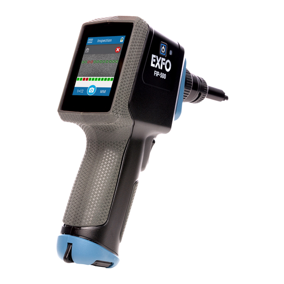
Introducing the FIP-500 Fiber Inspection Scope The FIP-500 Fiber Inspection Scope is a portable video microscope used to inspect optical fiber and cable ends. Its built-in 2.4-inch capacitive touchscreen and quick-change SmarTips facilitate the examination of patchcord connectors and also hard-to-reach connectors on the back of patch panels and bulkhead adapters. - Page 12 Introducing the FIP-500 Fiber Inspection Scope Main Features AUTION The optical head of your unit contains precision components. To ensure optimum protection when you do not use the unit or during transportation, cover the optical head with the provided protective cap.
- Page 13 Introducing the FIP-500 Fiber Inspection Scope Main Features Back view Touchscreen Fiber Inspection Scope...
-
Page 14: Available Configurations
Introducing the FIP-500 Fiber Inspection Scope Available Configurations Bottom view USB 2.0 Type-C connector for battery charging (see Power Sources on page 8) Available Configurations Several configurations are available for the fully automated and wireless FIP-500 Fiber Inspection Scope: Configuration Description To inspect single-fiber connectors. -
Page 15: Led Indicators Description
Introducing the FIP-500 Fiber Inspection Scope LED Indicators Description LED Indicators Description Your unit is equipped with a battery LED and a dual-function LED. Battery LED The battery LED, located next to the power button, on the side of your unit, provides you with information about the battery status. - Page 16 Introducing the FIP-500 Fiber Inspection Scope LED Indicators Description Dual-Function LED The dual-function LED is located just above the trigger used for captures, on the front of your unit. It can indicate the status of the inspection or be used as a flashlight to help you see the connectors you have to inspect in darker environments (see Turning on or Turning off the Flashlight on page 51).
-
Page 17: Battery Status Icon Description
Introducing the FIP-500 Fiber Inspection Scope Battery Status Icon Description Battery Status Icon Description The battery status icon is shown in the upper right corner of the title bar. It complements the information provided by the unit’s LED. Icon Meaning The portion of the icon that appears in white in the title bar (in gray here) reflects the current battery level. -
Page 18: Power Sources
Introducing the FIP-500 Fiber Inspection Scope Power Sources Power Sources The Fiber Inspection Scope operates with the following power sources: Indoor use only: USB power adapter connected to a power outlet (fastest way to charge the battery). Note: The standard USB ports of a computer cannot power your unit or charge its battery while the unit is on. -
Page 19: Technical Specifications
Introducing the FIP-500 Fiber Inspection Scope Technical Specifications Technical Specifications To obtain this product’s technical specifications, visit the EXFO Web site at www.exfo.com. Conventions Before using the product described in this guide, you should understand the following conventions: ARNING Indicates a potentially hazardous situation which, if not avoided, could result in death or serious injury. -
Page 21: Safety Information
ARNING Use only accessories designed for your unit and approved by EXFO. For a complete list of accessories available for your unit, refer to its technical specifications or contact EXFO. - Page 22 General Safety Information MPORTANT Refer to the documentation provided by the manufacturers of any accessories used with your EXFO product. It may contain environmental and/or operating conditions limiting their use. MPORTANT When you see the following symbol on your unit...
-
Page 23: Other Safety Symbols On Your Unit
Safety Information Other Safety Symbols on Your Unit Other Safety Symbols on Your Unit One or more of the following symbols may also appear on your unit. Symbol Meaning Direct current Alternating current The unit is equipped with an earth (ground) terminal. The unit is equipped with a protective conductor terminal. -
Page 24: Electrical Safety Information
ES1 circuits only. Use only the listed and certified USB power adapter provided by EXFO with your unit. It provides reinforced insulation between primary and secondary, and is suitably rated for the country where the unit is sold. - Page 25 Safety Information Electrical Safety Information AUTION Position the unit so that the air can circulate freely around it. When you use the unit outdoors, ensure that it is protected from liquids, dust, direct sunlight, precipitation, and full wind pressure.
- Page 26 Measured in 0 °C to 31 °C (32 °F to 87.8 °F) range, decreasing linearly to 50 % at 40 °C (104 °F). Equipment must be normally protected against exposure to direct sunlight, precipitation and full wind pressure. Not exceeding ± 10 % of the nominal voltage. FIP-500...
-
Page 27: Getting Started With Your Unit
Turning on Your Unit When you turn on the unit for the very first time, you will be prompted to read and accept the EXFO license agreement and set the date and time (see the section about the first startup for more information). -
Page 28: Turning Off Your Unit
To exit the sleep mode and resume your work: Press the on/off button or press the trigger. To turn off the unit completely (shutdown): Press the on/off button for about three seconds. A shutdown animation will be displayed on the screen. FIP-500... -
Page 29: Configuring Your Unit At First Startup
Unless otherwise specified, the information applies both to the Android- and iOS-based smart devices. Note: Both on your unit and in the EXFO Exchange application, the period is used as the decimal separator in numerical values, when applicable. - Page 30 4b. Select the I have read the safety instructions box, then tap Next. 5. Tap Close when you have finished. 6. EXFO recommends to configure a Wi-Fi network that will allow you to retrieve the software updates. You can proceed as follows: 6a.
-
Page 31: Understanding The Inspection Screen
Getting Started with Your Unit Understanding the Inspection Screen Understanding the Inspection Screen From the inspection screen, you can take captures of connectors under inspection and view these captures. The inspection screen also shows the title bar, which provides information on many elements such as the Bluetooth connection, Wi-Fi connection and signal strength, as well as battery level. -
Page 32: Changing Your Unit's Smartip
SmarTip–optical head assembly instead. For more information, see Changing Your Unit’s Optical Head on page 26. The illustrations shown in the procedure hereafter are for the multi-fiber SmarTips, but the principle remains the same for the single-fiber SmarTips. FIP-500... - Page 33 Getting Started with Your Unit Changing Your Unit’s SmarTip To change your unit’s SmarTip: 1. If necessary, remove the protective cap from the unit. 2. Turn the SmarTip retaining nut counterclockwise until the pins are aligned with the widest part of the SmarTip anchoring slots. Widest part of the SmarTip anchoring slot Fiber Inspection Scope...
- Page 34 Desired key orientation (when applicable; should be visible as shown below) Pins Optical head Widest part of the SmarTip anchoring slots 5. Slide the SmarTip toward the unit until it stops. FIP-500...
- Page 35 Getting Started with Your Unit Changing Your Unit’s SmarTip 6. Turn the SmarTip retaining nut clockwise until the pins are aligned with the narrowest part of the anchoring slots to secure the SmarTip in place. The new SmarTip is now ready to use. Fiber Inspection Scope...
-
Page 36: Changing Your Unit's Optical Head
1. Slightly turn the optical head retaining nut counterclockwise to release it from your unit (the pins on the unit will be aligned with the widest part of the anchoring slots on the optical head). Widest part of the optical head anchoring slot FIP-500... - Page 37 Getting Started with Your Unit Changing Your Unit’s Optical Head 2. Gently pull on the optical head to remove it. Fiber Inspection Scope...
- Page 38 Getting Started with Your Unit Changing Your Unit’s Optical Head 3. Align the arrow on the new optical head with the arrow on your unit and then, gently put the optical head back in place. Alignment arrows FIP-500...
- Page 39 Getting Started with Your Unit Changing Your Unit’s Optical Head 4. Slightly turn the optical head retaining nut clockwise to secure it in place (the pins on the unit will be aligned with the narrowest part of the anchoring slots on the optical head). 5.
-
Page 40: Cleaning And Connecting Optical Fibers
To ensure maximum power and to avoid erroneous readings: Always inspect fiber ends and make sure that they are clean as explained below before inserting them into the port. EXFO is not responsible for damage or errors caused by bad fiber cleaning or handling. - Page 41 EXFO uses good quality connectors in compliance with EIA-455-21A standards. To keep connectors clean and in good condition, EXFO strongly recommends inspecting them with a fiber inspection scope (or probe) before connecting them. Failure to do so may result in permanent damage to the connectors and degradation in measurements.
-
Page 42: Temperature Management
If the unit was left in a vehicle during cold weather, you will have to let your unit warm up before using it. Ensure that your unit is normally protected from direct sunlight (during use and storage). FIP-500... -
Page 43: Setting Up Your Unit
Setting up Your Unit Adjusting Display Brightness You may want to adjust the display brightness yourself to better fit your work environment or preferences. You may also want to reduce the display brightness to save battery power (the higher the brightness level, the higher the power consumption). The brightness value is kept in memory even when you turn the unit off. -
Page 44: Adjusting The Date And Time
The new brightness value is taken into account immediately. Adjusting the Date and Time The date and time are expressed in international format. You can adjust them if necessary. To adjust the date or time manually: 1. From the main menu, tap Settings. FIP-500... - Page 45 Setting up Your Unit Adjusting the Date and Time 2. Scroll down to the Unit settings section. 3. Tap Date and time. 4. Tap the entry corresponding to the element that you want to modify. 5. Modify the settings according to your needs, and then tap to return to the Date and time screen.
-
Page 46: Configuring The Sleep Mode
The unit will not enter sleep mode while you use the unit or perform captures. To configure the duration after which the unit enters sleep mode: 1. From the main menu, tap Settings. 2. Scroll down to the Unit settings section. FIP-500... - Page 47 Setting up Your Unit Configuring the Sleep Mode 3. Tap Sleep. 4. Select the desired number of minutes, and then tap to return to the Date and time screen. The new value is taken into account immediately. Fiber Inspection Scope...
-
Page 48: Reverting To Factory Settings
This operation does not affect the current date and time and does not delete any stored test data. To revert values to factory settings: 1. From the main menu, tap Settings. 2. Scroll down to the Unit settings section. FIP-500... - Page 49 Setting up Your Unit Reverting to Factory Settings 3. Tap Reset options. 4. Tap Factory settings. 5. Tap RESET to confirm your choice and start the operation. When the operation is complete, the unit will restart. 6. Configure the date and time, and accept the license agreement as you did when you first received your unit (see Configuring Your Unit at First Startup on page 19).
-
Page 51: Inspecting Fiber Ends
ARNING Never look directly into a live fiber. It could cause serious eye damage. Always use your FIP-500 Fiber Inspection Scope. To protect your eyes, do not stare into the violet light that comes out of your unit. - Page 52 1. From the inspection screen, tap SF (single-fiber connector type currently selected) or the numbers corresponding to the fiber layout (multi-fiber type selected). Multi-fiber connector type currently selected 2. In the Connector type screen, select the type of connector you want to use. FIP-500...
- Page 53 Inspecting Fiber Ends Selecting the Connector and Interface Types 3. If you work with multi-fiber connectors, proceed as follows. 3a. Select the fiber layout corresponding to the connector you want to inspect. 3b. Select the key orientation of the connector that best suits your work environment.
-
Page 54: Selecting The Fiber Type
The possible fiber types for these connectors are listed below. Fiber Type Features Singlemode Corresponds to singlemode fiber with a PC or (single-fiber UPC connector. connectors only) Fiber type selected by default. Fiber jacket is usually yellow and connector is dark blue. FIP-500... - Page 55 Inspecting Fiber Ends Selecting the Fiber Type Fiber Type Features Singlemode APC Fiber type selected by default for multi-fiber connectors. Fiber jacket is usually yellow and connector is green. Multimode OM1 Modal bandwidth: 200-500 MHz·km. Fiber channel designation: M6. Fiber jacket is orange or slate. Multimode OM2 Modal bandwidth: 500 MHz·km.
- Page 56 2. In the Fiber type screen, select the desired type of fiber. If you are not sure whether your setup uses singlemode or multimode fiber, you can have a look at the color chart displayed on the screen. The new settings will be taken into account for the next inspection. FIP-500...
-
Page 57: Inspecting Fiber Ends
Inspecting Fiber Ends Inspecting Fiber Ends Inspecting Fiber Ends Your unit allows you to inspect both single- and multi-fiber connectors. Before beginning to inspect fiber ends, you must first ensure that the appropriate optical head is installed on your unit. You must ensure that the SmarTip installed on your unit corresponds to the type of connector that you need to inspect. -
Page 58: Navigating Through Multi-Fiber Captures
To scroll through the inspection results: Swipe left or right on the screen. To switch from one fiber row to the other (multi-row fiber layouts): Swipe up or down on the screen. FIP-500... - Page 59 Inspecting Fiber Ends Navigating Through Multi-Fiber Captures To access the detailed capture of any of the inspected fibers: From the overview, tap the image of the fiber (small circle) or the desired fiber number. Global pass/fail status of the connector Image of a fiber Fiber number To return to the overview:...
-
Page 60: Displaying Or Hiding The Overlay
To display or hide the overlay: Tap the icon. Tap either anywhere in the non-active area (gray background) of the image or directly on the image of the fiber when you view a specific fiber. FIP-500... -
Page 61: Turning On Or Turning Off The Flashlight
Inspecting Fiber Ends Turning on or Turning off the Flashlight Turning on or Turning off the Flashlight Your unit comes equipped with a dual-function LED that can serve as a flashlight to help you locate the connectors. This is particularly useful when the environment in which you must perform the inspection is dark. -
Page 63: Working With The Exfo Exchange Application
Working with the EXFO Exchange Application You can use your FIP-500 in association with a smart device equipped with the EXFO Exchange application allowing you to retrieve the software updates and send captures to EXFO for technical support. Note: Depending on the type of smart device you are using, the appearance of the EXFO Exchange application may vary slightly from the illustrations presented in this documentation. -
Page 64: Establishing Or Closing A Connection With A Smart Device Via The Bluetooth Technology
(see Enabling or Disabling the Wireless Communication on page 59). On your FIP-500 unit, the status of the Bluetooth communication is indicated with an icon in the title bar. The table below shows the possibilities. - Page 65 1. If necessary, enable the Bluetooth communication on your unit (see Enabling or Disabling the Wireless Communication on page 59). 2. If it is not already done, install the EXFO Exchange application on your smart device (see Installing the EXFO Exchange Application on Your Smart Device on page 53).
- Page 66 FIP-500 unit. The unit (identified with its serial number) is added to the list of test units in EXFO Exchange. Note: If the FIP-500 unit that you want to use is already connected to another smart device, you must first close the connection between the FIP-500 unit and the other smart device before being able to see it on the list of the nearby FIP-500 units.
- Page 67 Working with the EXFO Exchange Application Establishing or Closing a Connection With a Smart Device Via the Bluetooth Technology To close the connection with a smart device from your unit: 1. From the main menu, tap Settings. 2. From the Wireless section, tap Disconnect mobile app.
- Page 68 1. From the Test units screen, tap the line corresponding to your FIP-500 unit. 2. Tap FORGET THIS TEST UNIT. The smart device is no longer connected to the FIP-500 and you are ready to connect it to another unit. FIP-500...
-
Page 69: Enabling Or Disabling The Wireless Communication
Wi-Fi is not. You can enable or disable the Bluetooth communication from your unit only, and the Wi-Fi communication both from your unit and from the EXFO Exchange application. If you do not need to connect to a wireless network for a certain period of time, you may wish to disable the Wi-Fi communication to save battery power. - Page 70 Working with the EXFO Exchange Application Enabling or Disabling the Wireless Communication To enable or disable the wireless communication from your unit: 1. From the main menu, tap Settings. 2. From the Wireless section, use the Wi-Fi or Bluetooth toggle to enable or disable the communication as needed.
- Page 71 Connection With a Smart Device Via the Bluetooth Technology on page 54). 2. On the smart device, open the EXFO Exchange application. 3. From the Test units screen, tap the line corresponding to your FIP-500 unit. 4. Tap Wi-Fi. 5. Use the Wi-Fi toggle to enable or disable the Wi-Fi communication.
-
Page 72: Working With A Wireless Network
(see on page 66). By default, the Wi-Fi connection is disabled on the FIP-500 unit. You must enable it before trying to connect to a wireless network (see Enabling or Disabling the Wireless Communication on page 59). - Page 73 The information about the Wi-Fi connection is indicated with an icon appearing both in the title bar (on your unit) and next to the name of the wireless networks (in the EXFO Exchange application). The table below shows the possibilities.
- Page 74 Configuring a Wireless Network Before being able to connect your unit to a Wi-Fi network, you must first configure the desired networks with the EXFO Exchange application. Once the configuration and first connection are successful, the configured network is automatically added to the list of possible networks on your unit.
- Page 75 Working with the EXFO Exchange Application Working With a Wireless Network 4. From the Test units screen, tap the line corresponding to your FIP-500 unit. 5. Tap Wi-Fi. 6. Tap the item corresponding to the wireless network that you want to configure.
- Page 76 Working with the EXFO Exchange Application Working With a Wireless Network 7. If the network is protected by a network security key (password), enter 8. Tap CONNECT. 9. Follow the on-screen instructions. The application establishes the communication automatically. Connecting to a Wireless Network From Your Unit...
-
Page 77: Maintenance
Maintenance To help ensure long, trouble-free operation: Always inspect fiber-optic connectors before using them and clean them if necessary. Keep the unit free of dust. Clean the unit casing and front panel with a cloth slightly dampened with water. -
Page 78: Cleaning Lenses
MPORTANT EXFO recommends to clean the lenses only when necessary, beginning with the parts that are the most exposed to dust and dirt. For example, the lens that is located at the end of the optical head (just behind the SmarTip) can need cleaning, but not the other lenses. - Page 79 Maintenance Cleaning Lenses To clean lenses: 1. If necessary, turn off your unit and remove the protective cap. 2. Turn the SmarTip retaining nut counterclockwise until the pins are aligned with the widest part of the SmarTip anchoring slots. Widest part of the SmarTip anchoring slot Fiber Inspection Scope...
- Page 80 Maintenance Cleaning Lenses 3. Pull on the SmarTip to remove it. Optical head 4. Clean the lens that is located at the end of the optical head. Multi-fiber optical head Lens FIP-500...
- Page 81 Maintenance Cleaning Lenses Single-fiber optical head Lens Fiber Inspection Scope...
- Page 82 5. Slightly turn the optical head retaining nut counterclockwise to release it from your unit (the pins on the unit will be aligned with the widest part of the anchoring slots on the optical head). Widest part of the optical head anchoring slot FIP-500...
- Page 83 Maintenance Cleaning Lenses 6. Gently pull on the optical head to remove it. Fiber Inspection Scope...
- Page 84 Note: You will need a swab measuring at least 15 cm (6 inches) to clean the inner part of the single-fiber optical head lens. Multi-fiber optical head Inner part of the lens Single-fiber optical head Inner part of the lens FIP-500...
- Page 85 Maintenance Cleaning Lenses 8. Using a lint-free swab, clean the focus lens. Focus lens Fiber Inspection Scope...
- Page 86 Maintenance Cleaning Lenses 9. Align the arrow on the optical head with the arrow on your unit and then, gently put the optical head back in place. Alignment arrows FIP-500...
- Page 87 Maintenance Cleaning Lenses 10. Slightly turn the optical head retaining nut clockwise to secure it in place (the pins on the unit will be aligned with the narrowest part of the anchoring slots on the optical head). Fiber Inspection Scope...
-
Page 88: Cleaning The Touchscreen
Your unit is now ready to use. Cleaning the Touchscreen Clean the touchscreen with a soft, non-abrasive cloth, such as one used for cleaning reading glasses, dampened with water. AUTION Using anything else than water can damage the special coating of the touchscreen. FIP-500... -
Page 89: Battery Maintenance Recommendations
Your unit uses the following type of batteries: Lithium-ion (Li-ion). These are batteries with built-in protection that have been especially designed for EXFO. For this reason, you can only replace them with EXFO-approved batteries of the same type and model. - Page 90 Maintenance Battery Maintenance Recommendations At EXFO, we take the safety of our customers very seriously and want to make sure any battery replacement is done properly. The batteries of all EXFO-branded products are tested, certified, and in compliance with these international safety standards: United Nations (UN) Transport Regulations UN38.3: Covers battery...
-
Page 91: Recharging The Battery
(see LED Indicators Description on page 5). ARNING Use only the listed and certified USB power adapter provided by EXFO with your unit. It provides reinforced insulation between primary and secondary, and is suitably rated for the country where the unit is sold. - Page 92 Recharge the battery when necessary, so that its charge level remains around 50 % of the total capacity. This will ensure that you get the optimum performance out of the battery. FIP-500...
- Page 93 Maintenance Recharging the Battery To recharge the battery: Connect the unit to a power outlet using the USB power adapter (fastest way to charge the battery). Note: The standard USB ports of a computer cannot power your unit or charge its battery while the unit is on.
-
Page 94: Replacing The Battery
Your unit uses a lithium-ion (Li-ion) battery with built-in protection that has been especially designed for EXFO. For this reason, you can only replace it with batteries of the same type and model. The use of other batteries may damage your unit and compromise your safety. - Page 95 Maintenance Replacing the Battery To replace the battery: 1. Turn off the unit by pressing the on/off button for about three seconds. A shutdown animation will be displayed on the screen. 2. If applicable, disconnect the USB cable. 3. Position the unit so that its side panel with the on/off button rests on a flat surface such as a table.
- Page 96 Maintenance Replacing the Battery 5. Hold the cover by its sides and pull it up to remove it. FIP-500...
- Page 97 Maintenance Replacing the Battery 6. Gently pull on the battery connector to disconnect it from its socket. Battery connector Battery wires Battery Fiber Inspection Scope...
- Page 98 7. Pull the battery up to remove it. Socket for battery connection...
- Page 99 Maintenance Replacing the Battery 8. Place the new battery so that its wires and connector are located on the same side as the socket in your unit’s case. The battery connector should be facing down. 9. Place the new battery in the bottom of the case. Socket for battery connection 10.
- Page 100 It could take a few charge/discharge cycles before the battery LED indicator and the on-screen battery status icon reflect the actual power level of the new battery. FIP-500...
-
Page 101: Upgrading Software
Maintenance Upgrading Software Upgrading Software Note: You need a smart device equipped with the EXFO Exchange application to be able to configure a wireless network, connect your unit to it, and then receive the available updates. Your unit’s application has been preinstalled and configured at the factory. -
Page 102: Recycling And Disposal
This symbol on the product means that you should recycle or dispose of your product (including electric and electronic accessories) properly, in accordance with local regulations. Do not dispose of it in ordinary garbage receptacles. For complete recycling/disposal information, visit the EXFO Web site at www.exfo.com/recycle. FIP-500... -
Page 103: Troubleshooting
If the problem persists, try resetting the FIP-500 to its factory settings (see Reverting to Factory Settings on page 38). My unit is not The system has Press the on/off button for at least responding. - Page 104 USB power adapter is defective. In this case, try replacing the adapter. You can purchase new USB power adapters from EXFO. Ambient temperature is In this case, the battery LED is blue too high or too low.
- Page 105 No network has been You must first configure the desired network is displayed. configured yet. networks on your smart device, using in the EXFO Exchange application (see Working With a Wireless Network on page 62). My unit does not There is a connection Ensure that the Wi-Fi ...
-
Page 106: Restoring Your Unit To Normal Operation
All data and custom configurations stored on your unit will be permanently lost. Follow the procedure below carefully and connect your unit to a power outlet using the provided USB power adapter when you are instructed to do so. FIP-500... - Page 107 Troubleshooting Restoring Your Unit to Normal Operation To restore you unit to normal operation: 1. Ensure that your unit is completely off (not in sleep mode). If necessary, turn off your unit by pressing the on/off button for about three seconds. A shutdown animation will be displayed on the screen. 2.
- Page 108 8. A message will inform you when the operation is complete. Tap RESTART. 9. Once your unit has restarted, read and accept the EXFO license agreement, set the date and time, and read safety instructions as you did when you first received your unit (see Configuring Your Unit at First Startup on page 19).
-
Page 109: Accessing The Online Documentation
Accessing the Online Documentation You can access the user guide at all times from your smart device. Note: The user guide is also available from the EXFO Web site (www.exfo.com) for download in PDF format. To access the user guide with the QR code: 1. - Page 110 Troubleshooting Accessing the Online Documentation 3. Tap Support. 4. Use a smart device to scan the QR code and access the user guide. FIP-500...
-
Page 111: Contacting The Technical Support Group
Contacting the Technical Support Group To obtain after-sales service or technical support for this product, contact EXFO at one of the following numbers. The Technical Support Group is available to take your calls from Monday to Friday, 8:00 a.m. to 7:00 p.m. -
Page 112: Sharing Information With The Technical Support Group
Sharing Information With the Technical Support Group Sharing Information With the Technical Support Group After contacting EXFO for support, you may need to share captures with the technical support group for further investigation. To accelerate the process, please have information such as the serial number of your unit as well as the approximative date and time when the captures were taken, close at hand. - Page 113 Troubleshooting Sharing Information With the Technical Support Group To share information with the technical support group: 1. From the main menu, tap Settings. 2. Scroll down to the Unit settings section. 3. Tap Support. Fiber Inspection Scope...
- Page 114 Sharing Information With the Technical Support Group 4. Tap Share captures with EXFO. Note: If the Share captures with EXFO link is not available (dimmed), it means that all the captures have been transferred to the support server already. 5. When the application prompts you, read the information and tap the SHARE button to authorize the transfer.
-
Page 115: Viewing System Information
You can also find the contact information if you ever need to reach EXFO. To view the system information: 1. From the main menu, tap Settings. - Page 116 Troubleshooting Viewing System Information 3. Tap About. The information you want to view is displayed on the screen. FIP-500...
- Page 117 Troubleshooting Viewing System Information To retrieve the contact information: 1. From the main menu, tap Settings. 2. Scroll down to the Unit settings section. 3. Tap Support. Fiber Inspection Scope...
-
Page 118: Transportation
Avoid high humidity or large temperature fluctuations. Keep the unit out of direct sunlight. Avoid unnecessary shocks and vibrations. MPORTANT To prevent the unit from turning on unexpectedly, always turn it off (shutdown) before transporting it. FIP-500... -
Page 119: Warranty
Warranty General Information EXFO Inc. (EXFO) warrants this equipment against defects in material and workmanship for a period of one year from the date of original shipment. EXFO also warrants that this equipment will meet applicable specifications under normal use. -
Page 120: Gray Market And Gray Market Products
(hereafter unauthorized intermediary). EXFO considers that a product originates from the gray market (hereafter gray market product) in the following situations: A product is sold by an unauthorized intermediary. -
Page 121: Liability
Liability Liability EXFO shall not be liable for damages resulting from the use of the product, nor shall be responsible for any failure in the performance of other items to which the product is connected or the operation of any system of which the product may be a part. -
Page 122: Service And Repairs
5. Return the equipment, prepaid, to the address given to you by support personnel. Be sure to write the RMA number on the shipping slip. EXFO will refuse and return any package that does not bear an RMA number. -
Page 123: Exfo Service Centers Worldwide
Fax: +86 (755) 2955 3101 Xintian Avenue, support.asia@exfo.com Fuhai, Bao’An District, Shenzhen, China, 518103 To view EXFO's network of partner-operated Certified Service Centers nearest you, please consult EXFO's corporate website for the complete list of service partners: http://www.exfo.com/support/services/instrument-services/ exfo-service-centers. Fiber Inspection Scope... -
Page 125: Index
Index Index brightness adjusting..........33 AC requirements ........15, 16 icon............34 accessing online help ........99 button, on/off......2, 5, 17, 82, 85 adapter ..........14, 81 adjusting brightness..........33 capacitors ............ 14 date and time ........34 captures after-sales service ........ - Page 126 Bluetooth ........54, 55 EXFO Exchange application....53 with a wireless network......66 software..........91 EXFO Exchange application, installation..53 integrated light ........... 51 external power supply......14, 81 internal temperature ....... 8, 32 IPv4 wireless routers, characteristics.... 62 factory settings ........
- Page 127 38, 96 see also USB power adapter sleep mode ..........36 sources ..........16 software update ........91 supply ..........14, 81 wireless communication ......59 preferred networks........ 62, 64 wireless network ........62 shipping to EXFO........112 Fiber Inspection Scope...
- Page 128 IPv4 routers characteristics..... 62 Wi-Fi or Bluetooth ......... 59 networks.......... 62, 64 wizard, configuration ........19 understanding inspection screen....21 unit first configuration........19 repairing ..........14 restoring ..........96 unexpected shutdown ......32 ventilation ..........15 updating applications ......... 91 FIP-500...
- Page 131 · info@EXFO.com CORPORATE HEADQUARTERS 400 Godin Avenue Quebec (Quebec) G1M 2K2 CANADA Tel.: 1 418 683-0211 · Fax: 1 418 683-2170 TOLL-FREE (USA and Canada) 1 800 663-3936 © 2021 EXFO Inc. All rights reserved. Printed in Canada (2021-09) ...
Need help?
Do you have a question about the FIP-500 and is the answer not in the manual?
Questions and answers