Table of Contents
Advertisement
Quick Links
Advertisement
Table of Contents
Troubleshooting

Related Manuals for EXFO FLS-2600B


Summary of Contents for EXFO FLS-2600B
- Page 1 User Guide FLS-2600B Tunable Laser Source...
- Page 2 EXFO Inc. (EXFO). Information provided by EXFO is believed to be accurate and reliable. However, no responsibility is assumed by EXFO for its use nor for any infringements of patents or other rights of third parties that may result from its use.
-
Page 3: Table Of Contents
Contents Contents Certification Information ....................... vi 1 Introducing the FLS-2600B Tunable Laser Source ........1 General Information .......................1 RS-232 Connector Pinout ......................3 Typical Applications ........................4 Conventions ..........................5 2 Safety Information ..................7 Laser Safety Information ......................7 Electrical Safety Information ....................8 3 Getting Started with Your Tunable Laser Source ........ - Page 4 Contents 6 Operating your Tunable Laser Source ............39 Cleaning and Connecting Optical Fibers ................39 Installing the EXFO Universal Interface (EUI) .................41 Activating/Deactivating Light Emission .................42 Starting a Sweep ........................43 7 Maintenance ....................45 Cleaning Fixed Connectors ....................46 Cleaning EUI Connectors ......................48 Replacing the Fuse ........................50...
- Page 5 Contents C Remote Control ..................71 Setting the FLS-2600B for Remote Control ................71 Setting the GPIB Primary Address ..................72 Changing the Baud Rate for RS-232 ..................73 Changing the Flow Control for RS-232 .................74 Communication Parameters ....................75 Standard Status Data Structure ....................76 SCPI Commands ........................80...
-
Page 6: Certification Information
FCC Information Electronic test equipment is exempt from Part 15 compliance (FCC) in the United States. However, compliance verification tests are systematically performed on most EXFO equipment. Information Electronic test equipment is subject to the EMC Directive in the European Union. -
Page 7: Declaration Of Conformity
Hampshire, SO53 4SE, UNITED KINGDOM Equipment Type/Environment: Test & Measurement / Industrial Trade Name/Model No.: Tunable Laser Source / FLS-2600B Standard(s) to which Conformity is Declared: EN 61010-1:2001 Edition 2.0 Safety requirements for electrical equipment for measurement, control, and laboratory use... -
Page 9: Introducing The Fls-2600B Tunable Laser Source
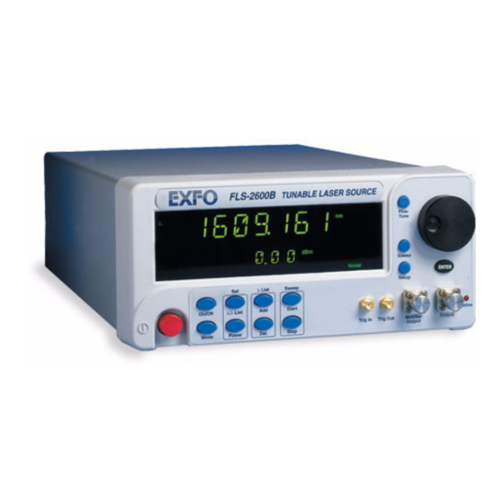
Introducing the FLS-2600B Tunable Laser Source General Information The FLS-2600B Tunable Laser Source addresses the testing requirements for dense WDM component testing in the C- and L-bands. Access to Setup menu Access to Sweep menu Fine-Tuning button FLS-2600B TUNABLE LASER SOURCE... - Page 10 Introducing the FLS-2600B Tunable Laser Source General Information GPIB port Serial port Fuse holder (RS-232 DTE) Power inlet Ground FLS-2600B...
-
Page 11: Rs-232 Connector Pinout
Introducing the FLS-2600B Tunable Laser Source RS-232 Connector Pinout RS-232 Connector Pinout The RS-232 connector (serial port) at the back of the FLS-2600B uses a DTE pinout configuration. 1 2 3 4 6 7 8 9 Description Direction Receive (Rc) -
Page 12: Typical Applications
Introducing the FLS-2600B Tunable Laser Source Typical Applications Typical Applications You can use your tunable laser source to perform several tasks, such as the following: characterizing filters, multiplexers, Bragg gratings, and other DWDM components checking wavelength-dependent gain, noise contribution and ... -
Page 13: Conventions
Introducing the FLS-2600B Tunable Laser Source Conventions Conventions Before using the product described in this manual, you should understand the following conventions: ARNING Indicates a potentially hazardous situation which, if not avoided, could result in death or serious injury. Do not proceed unless you understand and meet the required conditions. -
Page 15: Safety Information
Safety Information Laser Safety Information While handling optical fibers, laser radiation may be encountered at source output ports and fiber ends. Avoid long-term exposure to laser radiation. ARNING Do not install or terminate fibers while a light source is active. Never look directly into a live fiber and ensure that your eyes are protected at all times. -
Page 16: Electrical Safety Information
Failure to comply with these precautions or with specific indications elsewhere in this manual violates safety standards of intended use of the unit. EXFO assumes no liability for the user’s failure to comply with these requirements. This unit is intended for indoor use only. - Page 17 Safety Information Electrical Safety Information The unit must be positioned so as not to block the ventilation holes located on each side of the unit and to allow easy disconnection of the power cord if any problem should occur. Operation of any electrical instrument around flammable gases or ...
- Page 18 100 V to 240 V (50 Hz/60 Hz) maximum 2 A Measured in 0 °C to 31 °C (32 °F to 87.8 °F) range decreasing linearly to 50 % at 40 °C (104 °F). Not exceeding ± 10 % of the nominal voltage. FLS-2600B...
-
Page 19: Getting Started With Your Tunable Laser Source
Getting Started with Your Tunable Laser Source Turning on the Unit Before turning on the FLS-2600B, please read the Safety Information on page 7. To turn the unit on and off, use the red button in the lower left-hand corner of the front panel. - Page 20 Setup To move between the menu items, turn the selection dial. To exit a menu, press the button that gave access to it (Sweep or Setup). The FLS-2600B will return to its previous state. Note: The unit will beep whenever the FLS-2600B does not allow an operation.
-
Page 21: Positioning Your Unit Using The Support Stands
Getting Started with Your Tunable Laser Source Positioning Your Unit Using the Support Stands Positioning Your Unit Using the Support Stands To change the orientation of your unit, you can use the support stands located on the bottom front part of the casing. Simply pull them down until they lock into place. -
Page 23: Setting Standard Parameters
Setting Standard Parameters Setting the Display Intensity You might want to set the display intensity of your unit, or turn the display off. To change the display intensity: 1. Press Setup. 2. Turn the selection dial clockwise until DIMMER is displayed. The current dimmer status appears. -
Page 24: Turning The Sound On Or Off
3. Press ENTER. The Edit marker starts blinking in the lower part of the display. 4. Turn the selection dial until you reach the state you want (on or off), then press ENTER. To exit the Setup menu, press Setup. FLS-2600B... -
Page 25: Switching Between Normal And High-Resolution (Hr) Modes
Setting Standard Parameters Switching between Normal and High-Resolution (HR) Modes Switching between Normal and High-Resolution (HR) Modes In HR mode, the laser linewidth is reduced by a factor of 20 %. Typically, at 1550 nm, the Normal mode will produce a 1.6 GHz FWHM linewidth, while the HR mode will produce a 1.4 GHz FWHM linewith. -
Page 26: Selecting The Display Unit
3. Turn the selection dial clockwise or counterclockwise to select the desired unit (nm or THz). 4. Press ENTER to validate your choice and Setup to exit the Setup menu. The selection affects all relevant wavelength settings, including those in the Sweep. FLS-2600B... -
Page 27: Selecting A Wavelength
Setting Standard Parameters Selecting a Wavelength Selecting a Wavelength There are several ways to select a wavelength for testing. Entering a Wavelength Directly To select a wavelength, make sure you are in Wavelength Edition mode. To select the Wavelength Edition mode, press the List button on the ... - Page 28 The list number corresponding to your wavelength selection will appear for a few seconds, then the current power setting will reappear. To add a wavelength to the list, see Adding Items to Lists on page 22. FLS-2600B...
-
Page 29: Setting The Power
Setting Standard Parameters Setting the Power Setting the Power To set the output power, you must be in Power Edition mode. To select the Power Edition mode, press the Power button on the front panel, so that Power appears in the left part of the display. Fine-tune Power Normal... -
Page 30: Adding Items To Lists
To create an ascending list of wavelengths, enter your values beginning with the lowest and finishing with the highest. To create a descending list of wavelengths, simply enter your values from highest to lowest. FLS-2600B... -
Page 31: Deleting Items From Lists
Setting Standard Parameters Deleting Items from Lists Deleting Items from Lists You can delete items from the current list of wavelengths. To delete items: 1. Make sure you are in Wavelength List Edition mode ( List mode). To select the Wavelength List Edition mode, see Retrieving a Wavelength from a Stored List on page 20. -
Page 32: Using The Monitor Output
Using the Monitor Output Using the Monitor Output The monitor output of the FLS-2600B, located on the front of the unit, is mainly used to monitor the wavelength of the emitted signal with a wavelength meter. The power available through the monitor corresponds to approximately 10 % of the total power output, even though neither this fraction nor the power stability emitted are guaranteed. -
Page 33: Saving And Recalling Configurations
Setting Standard Parameters Saving and Recalling Configurations Saving and Recalling Configurations Once you have set the FLS-2600B Tunable Laser Source parameters, you can save your custom configuration and recall it at any time. You can also recall the factory-defined settings. - Page 34 4. Turn the selection dial clockwise or counterclockwise to select the desired number where you want to save your configuration. Edit Edit 5. Press ENTER to validate your choice, and Sweep to exit the Sweep menu. FLS-2600B...
-
Page 35: Reverting To Factory Settings
Setting Standard Parameters Reverting to Factory Settings Reverting to Factory Settings Turning on the unit and pressing ENTER at the same time until it beeps three times will reset the unit to the following default values: Parameters Reset Value or State ... -
Page 37: Setting Sweep Parameters
Setting Sweep Parameters Your tunable laser source allows you to perform automatic wavelength scans according to user-defined parameters. You can perform a continuous sweep (the source will make one or several continuous passes), or you can perform a step-by-step sweep (the signal wavelength changes according to preset increments or steps). -
Page 38: Selecting The Sweep Mode
4. Turn the selection dial clockwise or counterclockwise until the desired mode is displayed: Continuous (Cont.) or Step-by-Step (Step). Edit 5. Press ENTER to confirm your choice, and then Sweep to exit the Sweep menu. The sweeps will now be performed according to the mode you have selected. FLS-2600B... -
Page 39: Setting The Sweep Step
Setting Sweep Parameters Setting the Sweep Step Setting the Sweep Step You can set the size of the step (in nm or THz) for your step-by-step sweep. Your tunable laser source unit was designed to give a constant step value using nm as units. -
Page 40: Setting The Pauses
Selecting the Sweep Mode on page 30. To set the length of the pauses between the steps: 1. Press Sweep. 2. Turn the selection dial clockwise until PAUSE is displayed. 3. Press ENTER. The Edit marker starts blinking in bottom left-hand corner of the display. FLS-2600B... -
Page 41: Setting The Sweep Speed
Setting Sweep Parameters Setting the Sweep Speed 4. Turn the selection dial clockwise or counterclockwise to select the desired length of time for the pause. The pause range goes from 0.050 to 60.000 seconds. Fine-tune m/s/ms Edit 5. Press ENTER to validate your choice, and Sweep to exit the Sweep menu. - Page 42 Note: Setting the speed will automatically determine the duration of one pass according to the selected range. Your FLS-2600B unit was designed to give a constant speed value using nm as units. When the speed is given in a THz environment, the selected...
-
Page 43: Selecting The Incoming Trigger Option
Setting Sweep Parameters Selecting the Incoming Trigger Option Selecting the Incoming Trigger Option The incoming trigger option allows you to synchronize your sweeps with signals from other units. To switch the incoming trigger option on or off: 1. Press Sweep. 2. -
Page 44: Setting The Cycle Options
1 to 99. You can also select Continuous cycling by turning the selection dial counterclockwise until you pass 1. The display will then indicate Loop. Edit 5. Press ENTER to validate your choice, and Sweep to exit the Sweep menu. FLS-2600B... -
Page 45: Setting The Sweep Direction
The sweep can be either unidirectional, meaning that it will only go in one direction, or bidirectional, sweeping back and forth. This is set through the Reverse feature of your FLS-2600B. To set the direction of the sweep: 1. Press Sweep. -
Page 47: Operating Your Tunable Laser Source
To ensure maximum power and to avoid erroneous readings: Always inspect fiber ends and make sure that they are clean as explained below before inserting them into the port. EXFO is not responsible for damage or errors caused by bad fiber cleaning or handling. - Page 48 If your connector features a screwsleeve, tighten the connector enough to firmly maintain the fiber in place. Do not overtighten, as this will damage the fiber and the port. Note: If your fiber-optic cable is not properly aligned and/or connected, you will notice heavy loss and reflection. FLS-2600B...
-
Page 49: Installing The Exfo Universal Interface (Eui)
Operating your Tunable Laser Source Installing the EXFO Universal Interface (EUI) Installing the EXFO Universal Interface (EUI) The EUI fixed baseplate is available for connectors with angled (APC) or non-angled (UPC) polishing. A green border around the baseplate indicates that it is for APC-type connectors. -
Page 50: Activating/Deactivating Light Emission
If an error occured with the power prior to the source initialization, the active LED can take up to three seconds to light up. MPORTANT To obtain optimum stability, a laser source should be allowed to warm up for 60 minutes. FLS-2600B... -
Page 51: Starting A Sweep
Operating your Tunable Laser Source Starting a Sweep Starting a Sweep After setting your sweep parameters as explained in Setting Sweep Parameters on page 29 and that your source is turned on, you are ready to start your sweep. To start the sweep, press the Start button on the front panel. The system will perform the sweep according to the settings you have entered. -
Page 53: Maintenance
Maintenance To help ensure long, trouble-free operation: Always inspect fiber-optic connectors before using them and clean them if necessary. Keep the unit free of dust. Clean the unit casing and front panel with a cloth slightly dampened with water. -
Page 54: Cleaning Fixed Connectors
4. With a dry lint-free wiping cloth, gently wipe the same surfaces three times with a rotating movement. 5. Throw out the wiping cloths after one use. 6. Moisten a cleaning tip (2.5 mm tip) with only one drop of isopropyl alcohol. FLS-2600B... - Page 55 9. Continue to turn as you withdraw the cleaning tip. 10. Repeat steps 7 to 9, but this time with a dry cleaning tip (2.5 mm tip provided by EXFO). Note: Make sure you don’t touch the soft end of the cleaning tip and verify the cleanliness of the cotton tip.
-
Page 56: Cleaning Eui Connectors
3. Slowly insert the cleaning tip into the EUI adapter until it comes out on the other side (a slow clockwise rotating movement may help). 4. Gently turn the cleaning tip one full turn, then continue to turn as you withdraw it. FLS-2600B... - Page 57 6c. With a dry lint-free wiping cloth, gently wipe the same surfaces to ensure that the connector and ferrule are perfectly dry. 6d. Verify connector surface with a portable fiber-optic microscope (for example, EXFO’s FOMS) or fiber inspection probe (for example, EXFO’s FIP). ARNING Verifying the surface of the connector WHILE THE UNIT IS ACTIVE WILL result in permanent eye damage.
-
Page 58: Replacing The Fuse
Replacing the Fuse Replacing the Fuse The FLS-2600B contains two fuses of type IEC, 250 V, 2 A, fast blow 0.197 in x 0.787 in/5 mm x 20 mm. The fuse holder is located at the back of the FLS-2600B, just beside the power inlet. -
Page 59: Software Upgrades
Maintenance Software Upgrades Software Upgrades To upgrade the FLS-2600B embedded software using a diskette, you must connect your FLS-2600B to a computer through a null modem cable. Note: Software upgrades may be performed in DOS, Windows 3.1, Windows 95, Windows 98 or Windows 2000. If problems occur, please contact EXFO. - Page 60 4. Insert the upgrade diskette into the computer’s floppy disk drive and copy the *.hex file into the new directory (if necessary, unzip the file). 5. Connect one end of a null modem cable to the FLS-2600B RS-232 serial port and the other end to an unused communication port on your computer (ex.
- Page 61 Select “Close” to terminate the application. Click Close to hide the dialog box. 10. You must turn the FLS-2600B off, and then on again, to use the upgraded software. During self-test execution, the FLS-2600B should display the new software version number.
-
Page 62: Adjusting Your Unit According To Wavelength
4. Press ENTER. The Edit marker starts blinking in the lower part of the display. 5. Connect your FLS-2600B to a calibrated wavelength meter. 6. Turn the selection dial until you reach the wavelength value read on the wavelength meter, then press ENTER to validate it. - Page 63 Maintenance Adjusting Your Unit According to Wavelength 7. To exit the Setup menu, press Setup. Note: The difference between the pre-selected wavelength and the measured wavelength cannot be greater than ± 0.200 nm or ± 0.0250 THz. This user-performed calibration feature can help you achieve better absolute wavelength accuracy if, for example, you feel that conditions outside the unit may have affected the calibration.
-
Page 64: Recalibrating The Unit
You should determine the adequate calibration interval for your unit according to your accuracy requirements. Under normal use, EXFO recommends calibrating your unit every year. Recycling and Disposal (Applies to European Union Only) For complete recycling/disposal information as per European Directive WEEE 2002/96/EC, visit the EXFO Web site at www.exfo.com/recycle. -
Page 65: Troubleshooting
Solving Common Problems If you encounter one of the problems listed below, try to solve it first with the given information. In all cases, if the problem persists after performing a recommended action, contact EXFO immediately. Problem Probable Cause Recommended Action Source appears unstable. -
Page 66: Contacting The Technical Support Group
Contacting the Technical Support Group To obtain after-sales service or technical support for this product, contact EXFO at one of the following numbers. The Technical Support Group is available to take your calls from Monday to Friday, 8:00 a.m. to 7:00 p.m. -
Page 67: Transportation
Troubleshooting Transportation Transportation Maintain a temperature range within specifications when transporting the unit. Transportation damage can occur from improper handling. The following steps are recommended to minimize the possibility of damage: Pack the unit in its original packing material when shipping. ... -
Page 69: Warranty
Warranty General Information EXFO Inc. (EXFO) warrants this equipment against defects in material and workmanship for a period oftwo years from the date of original shipment. EXFO also warrants that this equipment will meet applicable specifications under normal use. During the warranty period, EXFO will, at its discretion, repair, replace,... -
Page 70: Liability
Liability Liability EXFO shall not be liable for damages resulting from the use of the product, nor shall be responsible for any failure in the performance of other items to which the product is connected or the operation of any system of which the product may be a part. -
Page 71: Exclusions
Warranty Exclusions Exclusions EXFO reserves the right to make changes in the design or construction of any of its products at any time without incurring obligation to make any changes whatsoever on units purchased. Accessories, including but not limited to fuses, pilot lamps, batteries and universal interfaces (EUI) used with EXFO products are not covered by this warranty. -
Page 72: Service And Repairs
5. Return the equipment, prepaid, to the address given to you by support personnel. Be sure to write the RMA number on the shipping slip. EXFO will refuse and return any package that does not bear an RMA number. -
Page 73: Exfo Service Centers Worldwide
Warranty EXFO Service Centers Worldwide EXFO Service Centers Worldwide If your product requires servicing, contact your nearest authorized service center. EXFO Headquarters Service Center 400 Godin Avenue 1 866 683-0155 (USA and Canada) Quebec (Quebec) G1M 2K2 Tel.: 1 418 683-5498... -
Page 75: A Technical Specifications
0.5 (typical Notes f. 1 nm step, one complete step through GPIB in manual mode with FLS-2600B. a. Specifications are valid at 23 °C ± 1 °C after one-hour warmup time. g. In normal mode. Operating in high-resolution mode (HR) typically reduces power level b. -
Page 76: Technical Specifications
3.4 kg (7.4 lb) Instruments Drivers LabVIEW™ drivers and SCPI commands Remote Control With FLS-2600B: GPIB (IEEE-488.1, IEEE-488.2) and RS-232. With IQS-500 or IQS-600: GPIB (IEEE-488.1, IEEE-488.2), Ethernet and RS-232. Standard Accessories User Guide, Certificate of Compliance and AC power cord... -
Page 77: B Trigger Option Theory
Trigger Option Theory Your Tunable Laser Source features Trigger In and Out connectors. When the trigger option is set to On, the Trigger In will wait for signals. The Trigger Out is always active and emits a signal for each one-way pass (Continuous mode) or step (Stepped mode) the system performs during the sweep. -
Page 78: Trigger Option In Stepped Mode
(b) second sweep trigger (c) trig received during the second sweep; kept in memory and will trigger the third sweep (d) trig received during the third sweep kept in memory and will trigger the fourth sweep (e) lost trig FLS-2600B... -
Page 79: C Remote Control
Source from EXFO’s IQS Series (IQS-2600B), you can reuse sections for the FLS-2600B. Setting the FLS-2600B for Remote Control To remotely control the FLS-2600B, you need to set a GPIB address or activate the RS-232 port. To set the remote control mode: 1. -
Page 80: Setting The Gpib Primary Address
Setting the GPIB Primary Address To set the GPIB primary address, you must be in GPIB mode. To select the GPIB mode, see Setting the FLS-2600B for Remote Control on page 71. To set the GPIB primary address: 1. Press Setup. -
Page 81: Changing The Baud Rate For Rs-232
Changing the Baud Rate for RS-232 Changing the Baud Rate for RS-232 To change the baud rate for RS-232 transfer, you must be in RS-232 mode. To select RS-232 mode, see Setting the FLS-2600B for Remote Control on page 71. To change the baud rate: 1. -
Page 82: Changing The Flow Control For Rs-232
The most common requirement is for flow control to match the data transmission rate to a rate the device can process. The computer and the terminal (in this case, the FLS-2600B) stop each other transmitting by sending a control character (xoff), and cause transmission to restart by sending another control character (xon). -
Page 83: Communication Parameters
Set EOI with EOS on Writes Type of compare on EOS 8 bits EOS byte Sens EOI at end of Writes GPIB primary address See Setting the FLS-2600B for Remote Control on page 71 GPIB secondary address None For RS-232 Communication EOS bytes... -
Page 84: Standard Status Data Structure
(SRQ) is generated. The four registers are described below: Standard Event Status Register (ESR) Bits Mnemonics Bit Value Power on Not used Command error Execution error Device-dependant error Query error Not used Operation complete FLS-2600B... - Page 85 Remote Control Standard Status Data Structure Standard Event Status Enable Register (ESE) Bits Mnemonics Bit Value Power on Not used Command error Execution error Device-dependent error Query error Not used Operation complete Status Byte Register (STB) Bits Mnemonics Bit Value Not used Request service/...
- Page 86 Remote Control Standard Status Data Structure Service Request Enable Register (SRE) Bits Mnemonics Bit Value Not used Reserved Event status byte Message available Not used Error/Event queue Not used Not used FLS-2600B...
- Page 87 Remote Control Standard Status Data Structure Tunable Laser Source...
-
Page 88: Scpi Commands
OUTP and STAT are keywords defining the function of the command. ] indicates that a keyword or parameter is optional. <wsp> indicates that a space is required ("wsp" stands for "white space"). <Boolean> indicates the command parameter. Keywords must be separated by a colon. FLS-2600B... - Page 89 Remote Control SCPI Commands To enter commands or queries you must use either the full word for the command, or the three- or four-letter shortcut. Commands are not case-sensitive; however, spelling errors will cancel the command or query. The command or query can be written using only shortcuts, only full words, or a combination of both.
-
Page 90: General Commands
Operation complete command *OPC? Operation complete query *REM? Set Remote programming state (RS-232 only) *RST Reset command *SRE Service request enable command *SRE? Service request enable query *STB? Read status byte query *TST? Self-test query The commands are fully explained hereafter. FLS-2600B... - Page 91 Remote Control General Commands *CLS Description This command sets the contents of the Standard Event Register (ESR), the Status Byte Register (STB), and the Error Queue (ERR) to zero. This command is commonly used to clear the status registers before enabling SRQ. Note that the output queue, Standard Event Status Enable Register (ESE), and Service Request Enable Register (SRE) are not affected.
- Page 92 Description This query reads the system identification string. Syntax *IDN? Response “EXFO E.-O. Eng. FLS-2600B vx.xx”xxxxxxxx xxxxxxx, where xxxxxxxx xxxxxxx is the serial number and vx.xx is the current product version. *LOK Description This command is used to set the Remote Lockout programming state.
- Page 93 This command can only be used when working with RS-232 communication. *OPC Description This command will cause the FLS-2600B to generate the operation complete message in the Standard Event Status Register (ESR) when all pending selected FLS-2600B operations have been completed.
- Page 94 Description This command is used to set the Remote programming state. Syntax *REM<wsp><data> Parameters The <data> parameter can be “1” to set the Remote programming state to Remote or “0” to set the Remote progamming state to Local. Note This command can only be used with RS-232 communication. FLS-2600B...
- Page 95 Remote Control General Commands *RST Description The *RST command sets the instrument to reset settings (factory settings stored in ROM). Pending *OPC and *OPC? actions are canceled. The instrument becomes idle. The *RST command clears the Input and Error queues. The following settings remain unchanged: Instrument interface address ...
- Page 96 Description This query returns the contents of the Service Request Enable Register (SRE). Syntax *SRE? Response An integer between 0 and 255. *STB? Description This query returns the contents of the Status Byte Register (STB). Syntax *STB? Response An integer between 0 and 255. FLS-2600B...
- Page 97 Remote Control General Commands *TST? Description This query initiates an internal self-test and returns a binary value indicating the results of the test. Syntax *TST? Response An integer indicating the sum of all corresponding errors: 0: No errors 1: Interlock ...
-
Page 98: Specific Commands
Remote Control Specific Commands Specific Commands CALibration:WAVelength Description This command introduces an offset into the FLS-2600B to correct a wavelength deviation as measured by a wavelength meter. Syntax CAL:WAV<wsp><wavelength> Parameters The <wavelength> parameter is a value indicating the wavelength in nm. - Page 99 Remote Control Specific Commands DISPlay:DIMMer Description This command allows you to set the dimmer state on the source. Syntax DISP:DIMM<wsp><state> Response The <state> parameter is a single digit indicating the state of the dimmer: 0 or Off 1 or Lo ...
- Page 100 0: Tunable 1: ASE Note This command cannot be performed if the FLS-2600B is performing a sweep. It will return an error if ASE is selected because it is not available. Example OUTP:MODE 0 See also...
- Page 101 Remote Control Specific Commands OUTPut:MODE? Description This query returns the current source mode (tunable or ASE). Syntax OUTP:MODE? Response A boolean value representing the current source mode: 0: tunable mode 1: ASE mode Note The response will always be “tunable mode”. See also OUTP:ASE?, OUTP:MODE, OUTP:STAT and OUTP:STAT? OUTPut:STATe...
- Page 102 The <mode> parameter is a boolean value representing the mode state: 0: Normal mode 1: High-Resolution mode Example SOUR:MODE 1 Note This command cannot be processed if your tunable laser source is performing a sweep. See also SOUR:MODE? FLS-2600B...
- Page 103 Remote Control Specific Commands SOURce:MODE? Description This query returns the current source mode. Syntax SOUR:MODE? Response A boolean value representing the current mode state: 0: Normal mode 1: High-Resolution mode See also SOUR:MODE SOURce:POWer:ALC Description This command activates the laser output Automatic Level Control (ALC).
- Page 104 Description When in Automatic Level Control (ALC) mode, this query returns the minimum source output power (in dBm) that can be set with the SOUR:POW command. Syntax SOUR:POW:LIM:LOW? Response The minimum source output power in ± 99.99 dBm format. See also SOUR:POW:LIM:HIGH?, and SOUR:POW:LIM:STEP? FLS-2600B...
- Page 105 Remote Control Specific Commands SOURce:POWer:LIMit:STEP? Description This query returns the minimum output power step (in dBm) that can be used when changing the source output power with the SOUR:POW command. Syntax SOUR:POW:LIM:STEP? Response The minimum output power step in ± 99.99 dBm format. See also SOUR:POW:LIM:HIGH?, and SOUR:POW:LIM:LOW? SOURce:SWEep:MODE...
- Page 106 (nm or THz). Syntax SOUR:SWE:CENT? Response The central wavelength for the current sweep program in the current spectral units in the 9999.999 nm or 999.9999 THz format. See also SOUR:SWE:MODE, SOUR:SWE:MODE?, SOUR:SWE:COUN, SOUR;SWE:COUN?, SOUR:SWE:REP , SOUR:SWE:REP?, SOUR:SWE:REV and SOUR:SWE:REV? FLS-2600B...
- Page 107 Remote Control Specific Commands SOURce:SWEep:COUNt Description This command is used to specify how many times you want the sweep program to loop. To specify whether or not you want the sweep program to loop, use the SOUR:SWE:REP command. Syntax SOUR:SWE:COUN<wsp><count> Parameters The <count>...
- Page 108 A boolean value indicating the state of the sweep repeat function: 1: the sweep repeat function is continuous. 0: the sweep repeat function is set to the number entered with the SOUR:SWE:COUN command. See also SOUR:SWE:MODE, SOUR:SWE:MODE?, SOUR:SWE:CENT, SOUR:SWE:COUN, SOUR;SWE:COUN?, SOUR:SWE:REP , SOUR:SWE:REV and SOUR:SWE:REV? FLS-2600B...
- Page 109 Remote Control Specific Commands SOURce:SWEep:REVerse Description This command is used to enable and disable the sweep reverse function. When this function is enabled, the sweep program is performed in both directions: ascending and descending. Syntax SOUR:SWE:REV<wsp><sweep> Parameters The <sweep> parameter is a boolean parameter indicating whether or not the sweep will be performede in both directions: 1: enable the sweep reverse function.
- Page 110 If you do not specify a unit, the system will return the value in the current spectral unit (nm or THz). To specify the units you want to use, add NM or THZ after your query (e.g., SOUR:SWE:STAR:WAV?<wsp>NM). See also SOUR:SWE:START:WAV, SOUR:SWE:STOP:WAV and SOUR:SWE:STOP:WAV? FLS-2600B...
- Page 111 Remote Control Specific Commands SOURce:SWEep:STOP:WAVelength Description This command allows you to specify a stop wavelength for the sweep. Syntax SOUR:SWE:STOP:WAV<wsp><wavelength> Parameters The <wavelength> parameter indicates the wavelength in 9999.999 nm or 999.9999 THz format. Example SOUR:SWE:STOP:WAV 1610.000 Note This command cannot be performed during a sweep. If you do not specify a unit, the system will use the current spectral unit (nm or THz).
- Page 112 Example SOUR:SWE:SPE 35.455 Note You cannot use this comment while the FLS-2600B is performing a sweep. If you do not specify a unit, the system will use the current spectral unit (nm/s or THz/s). To specify the units you want to use, add NM/S or THZ/S after your query (e.g., SOUR:SWE:SPE<wsp><speed><wsp>NM/S).
- Page 113 Remote Control Specific Commands SOURce:SWEep:SPEed? Description This query returns the sweep speed for the continuous mode. Syntax SOUR:SWE:SPE? Response Speed in 99.999 nm/s or 9.9999 THz/s format. See also SOUR:SWE:SPE Note If you do not specify a unit, the system will return the value in the current spectral unit (nm/s or THz/s).
- Page 114 Description This function starts or stops the sweep program. Syntax SOUR:SWE:STAT<wsp><state> Parameters The <state> parameter is a boolean parameter representing the new state of the sweep program: 1: sweep program started 0: sweep program stopped Example SOUR:SWE:STAT 1 See also SOUR:SWE:STAT?, SOUR:SWE:TIME? and SOUR:SWE:DUR? FLS-2600B...
- Page 115 Remote Control Specific Commands SOURce:SWEep:STATe? Description This query returns a value indicating the state of the sweep program. Syntax SOUR:SWE:STAT? Response A boolean value representing the current state of the sweep program: 1: the sweep program is in progress 0: the sweep program is not in progress ...
- Page 116 If you do not specify a unit, the system will return the value in the current spectral unit (nm or THz). To specify the units you want to use, add NM or THZ after your query (e.g., SOUR:SWE:STEP?<wsp>THZ). See also SOUR:SWE:STEP , SOUR:SWE:STEP:LIM:LOW?, SOUR:SWE:STEP:LIM:HIGH?, SOUR:SWE:PAUS and SOUR:SWE:PAUS? FLS-2600B...
- Page 117 Remote Control Specific Commands SOURce:SWEep:STEP:LIMit:HIGH? Description This query returns the largest possible wavelength step in a step-by-step sweep. Syntax SOUR:SWE:STEP:LIM:HIGH? Response Maximal wavelength step in 9999.999 nm or 999.9999 THz format. Note If you do not specify a unit, the system will return the value in the current spectral unit (nm or THz).
- Page 118 SOUR:SWE:PAUS:LIM:HIGH?, SOUR:SWE:TRIG and SOUR:SWE:TRIG? SOURce:SWEep:PAUSe? Description This query returns the minimal pause length between the steps for the step-by-step sweep. Syntax SOUR:SWE:PAUS? Response Time in 59:999 ms format. See also SOUR:SWE:STEP , SOUR:SWE:STEP:LIM:LOW?, SOUR:SWE:STEP:LIM:HIGH?, SOUR:SWE:STEP?, SOUR:SWE:PAUS, SOUR:SWE:PAUS:LIM:LOW?, SOUR:SWE:PAUS:LIM:HIGH?, SOUR:SWE:TRIG and SOUR:SWE:TRIG? FLS-2600B...
- Page 119 Remote Control Specific Commands SOURce:SWEep:PAUSe:LIMit:HIGH? Description This query returns the largest available pause for a step-by-step sweep. Syntax SOUR:SWE:PAUS:LIM:HIGH? Response Time in 59:999 ms format. See also SOUR:SWE:STEP , SOUR:SWE:STEP:LIM:LOW?, SOUR:SWE:STEP:LIM:HIGH?, SOUR:SWE:STEP?, SOUR:SWE:PAUS, SOUR:SWE:PAUS?, SOUR:SWE:PAUS:LIM:LOW?, SOUR:SWE:TRIG and SOUR:SWE:TRIG? SOURce:SWEep:PAUSe:LIMit:LOW? Description This query returns the smallest available pause for a step-by-step sweep.
- Page 120 Description This query returns the state of the input trigger option. Syntax SOUR:SWE:TRIG? Response A boolean expression indicating the trigger state: 1: active 0: inactive See also SOUR:SWE:STEP , SOUR:SWE:STEP:LIM:LOW?, SOUR:SWE:STEP:LIM:HIGH?, SOUR:SWE:STEP?, SOUR:SWE:PAUS, SOUR:SWE:PAUS?, SOUR:SWE:PAUS:LIM:LOW?, SOUR:SWE:PAUS:LIM:HIGH? and SOUR:SWE:TRIG FLS-2600B...
- Page 121 Remote Control Specific Commands SOURce:WAVelength Description This command selects a new source wavelength. Syntax SOUR:WAV<wsp><wave> Parameters The <wave> parameter represents the new wavelength in the 9999.999 nm or 999.9999 THz format. Note This function cannot be performed while the source is performing a sweep.
- Page 122 If you do not specify a unit, the system will return the value in the current spectral unit (nm or THz). To specify the units you want to use, add NM or THZ after your query (e.g., SOUR:WAV:LIM:LOW?<wsp>NM). See also SOUR:WAV, SOUR:WAV?, SOUR:WAV:LIM:HIGH?, SOUR:WAV:LIM:STEP?, UNIT:WAV, and UNIT:WAV? FLS-2600B...
- Page 123 Remote Control Specific Commands SOURce:WAVelength:LIMit:STEP? Description This query returns the minimum wavelength step that can be used when changing the wavelength with the SOUR:WAV command. Syntax SOUR:WAV:LIM:STEP? Response A value representing the minimum wavelength step available in the 9999.999 nm or 999.9999 THz format. Note If you do not specify a unit, the system will return the value in the current spectral unit (nm or THz).
- Page 124 Parameters The <unit> parameter is a boolean parameter representing the new spectral measurement unit: 1 – THz 0 – nm Note This command cannot be performed if the FLS-2600B is performing a sweep. Example UNIT:WAV 1 See also SOUR:WAV, SOUR:WAV?, SOUR:WAV:LIM:HIGH?, SOUR:WAV:LIM:LOW?, SOUR:WAV:LIM:STEP? and UNIT:WAV?
- Page 125 Remote Control Specific Commands UNIT:WAVelength? Description This query returns the current spectral measurement units. Syntax UNIT:WAV? Response A boolean value representing the current spectral measurement unit: 1 – THz 0 – nm See also SOUR:WAV, SOUR:WAV?, SOUR:WAV:LIM:HIGH?, SOUR:WAV:LIM:LOW?, SOUR:WAV:LIM:STEP? and UNIT:WAV Tunable Laser Source...
-
Page 126: Programming Commands
1 to 100 or 0 for continuous. The <rev> parameter indicates whether the reverse option is on or off. The format must be 1|0. The <trig> parameter indicates whether the trigger option is on or off. The format must be 1|0. FLS-2600B... - Page 127 Programming Commands SOURce:SWEep:CONTinuous:PROGram Note You cannot use this command while the FLS-2600B is performing a sweep. You do not have to enter all values in the command, but you must enter the values in the same order as in the Syntax section. If you want to enter only some of the values, use a comma ( , ) to separate the values, including the ones you did not enter.
- Page 128 1 to 100 or 0 (continuous). The <rev> parameter indicates whether the reverse option is on or off. The format must be 1|0. The <trig> parameter indicates whether the trigger option is on or off. The format must be 1|0. FLS-2600B...
- Page 129 Remote Control Programming Commands SOURce:SWEep:CONTinuous:PROGram? Note You cannot use this query while theTunable Laser Source is performing a sweep. You do not have to enter all values in the query, but you must enter the values in the same order as in the Syntax section. If you want to enter only some of the values, use a comma ( , ) to separate the values, including the ones you did not enter.
- Page 130 The format will be 1-99 or 0 (continuous). The <rev> parameter indicates whether the reverse option is on or off. The format must be 1/0. The <trig> parameter indicates whether the trigger option is on or off. The format must be 1/0. FLS-2600B...
- Page 131 Remote Control Programming Commands SOURce:SWEep:STEPped:PROGram Note You cannot use this command during a sweep. You do not have to enter all values in the command, but you must enter the values in the same order as in the Syntax section. If you want to enter only some of the values, use a comma ( , ) to separate the values, including the ones you did not enter.
- Page 132 The format will be 1-99 or 0 (continuous). The <rev> parameter indicates whether the reverse option is on or off. The format must be 1/0. The <trig> parameter indicates whether the trigger option is on or off. The format must be 1/0. FLS-2600B...
- Page 133 Remote Control Programming Commands SOURce:SWEep:STEPped:PROGram? Note You cannot use this query during a sweep. You do not have to enter all values in the query, but you must enter the values in the same order as in the Syntax section. If you want to enter only some of the values, use a comma ( , ) to separate the values, including the ones you did not enter.
-
Page 134: Other Commands
Description This function is used to recall a sweep setup saved in your list. Syntax SOUR:SWE:RECA<wsp><number> Parameters The <number> parameter represents the number of the item you want to recall. You can choose a number from 1 to 5. Example SOUR:SWE:RECA 3 Note You cannot use this command during a sweep. FLS-2600B... - Page 135 Remote Control Other Commands SOURce:SWEep:RECAll? Description This function is used to recall from a setup in your list. It also returns the validated parameters. Syntax SOUR:SWE:RECA?<wsp><number> Parameters The <number> parameter represents the number of the item you want to recall. You can choose a number from 1 to 5. Example SOUR:SWE:RECA? 3 Note...
-
Page 136: Quick Reference Command Tree
(ASE or Tunable). MODE? (0|1) Returns source mode. STAT <0|1> Turns source on or off. STAT? (1|0) Asks if the source is active. SOUR MODE <1|0> Sets source mode (Normal or High Resolution). MODE? (1|0) Requests current source mode. FLS-2600B... - Page 137 Remote Control Quick Reference Command Tree Parameter/ Command Description Response SOUR POW <±99.99> Sets source power. POW? (±99.99) Requests current source power. <0|1> Enables the automatic power level. ALC? (0|1) Asks if automatic power level is enabled. <9.99 dBm> Sets the output <9.999999 mW>...
- Page 138 Asks if reverse function active. STAR <9999.999> [nm] Sets start wavelength. <999.9999> [THz] STAR WAV? (9999.999) [nm] Requests current start (999.9999) [THz] wavelength. STOP <9999.999> [nm] Sets stop wavelength. <999.9999> [THz] STOP WAV? (9999.999) [nm] Requests current stop (999.9999) [THz] wavelength. FLS-2600B...
- Page 139 Remote Control Quick Reference Command Tree Parameter/ Command Description Response SOUR SWE SPAN? (9999.999) [nm] Returns wavelength (999.9999) [THz] span. <speed> Sets sweep speed. SPE? (99.999) [nm] Requests current sweep speed. HIGH? (99.999) [nm] Requests maximum sweep speed. LOW? (99.999) [nm] Requests minimum sweep speed.
- Page 140 TRIG? (1|0) Asks if Trigger In option on? <9999.999> [nm] Sets wavelength. <999.9999> [THz] WAV? (9999.999) [nm] Requests wavelength. (999.9999) [THz] HIGH? (9999.999) [nm] Requests max. wavelength. (999.9999) [THz] SOUR WAV LOW? (9999.999) [nm] Requests min. wavelength. (999.9999) [THz] FLS-2600B...
- Page 141 Remote Control Quick Reference Command Tree Parameter/ Command Description Response STEP? (9999.999) [nm] Requests min. wavelength (999.9999) [THz] step. SYST ERR? Error code Asks for next error in list. VERS? Current version Requests identification string. UNIT WAV <1|0> Sets wavelength unit.
-
Page 142: Error Messages
RECA? (1~5) Asks which sweep configuration is recalled. Error Messages System- and device-specific errors are managed by the FLS-2600B. The generic format for error messages is illustrated below. <Device-dependent ” <Error number> “ <Error description> information> As shown in the figure above, the message contains three parts: the error number, the error description, and device-dependent information. -
Page 143: Scpi Management Errors (System Errors)
Remote Control SCPI Management Errors (System Errors) SCPI Management Errors (System Errors) Error Description Probable Cause Number –100 Command error The SCPI Manager does not recognize the command, probably due to invalid module address. 104 Data-type error A data parameter is not the expected data type. - Page 144 Time-out error The Tunable Laser Source did not respond to the command within the given time-out period. 400 Query error Attempt to read an empty buffer or buffer data has been lost. 500 System error System is out of memory. FLS-2600B...
-
Page 145: Fls-2600B Error And Warning Messages
Remote Control FLS-2600B Error and Warning Messages FLS-2600B Error and Warning Messages Error or warning Description Recommended Action Number 11 Nulling was not performed Restart your Tunable Laser correctly. Source. 12 The Tunable Laser Source Contact EXFO. returns the wrong identification. - Page 146 Remote Control FLS-2600B Error and Warning Messages Error or warning Description Recommended Action Number 61 A problem occurred with the Contact EXFO. thermo-electric cooler. 62 The Flash memory was not Contact EXFO. detected by the tunable laser source. 63 The Flash reading was not Contact EXFO.
- Page 147 Remote Control FLS-2600B Error and Warning Messages Error or warning Description Recommended Action Number 101 The command request was Retry command or wait until not performed in the set time there are no commands in the amount. pipe. 102 The command was not Contact EXFO.
- Page 148 Remote Control FLS-2600B Error and Warning Messages Error or warning Description Recommended Action Number 32302 Not enough RAM to run the Restart the Tunable Laser command. Source. 32303 The Tunable Laser Source Restart the Tunable Laser attempted to perform a Source.
-
Page 149: Gpib Troubleshooting
Remote Control GPIB Troubleshooting GPIB Troubleshooting Problem Probable Cause Solution Unable to Incorrect Select the correct communicate with communication type communication type: the Tunable Laser selected. RS-232, GPIB, or DDE. Source (no response from *IDN? command). Incorrect Check the communication communication parameters. -
Page 151: Index
Index Index configuration recall ............25 activating the source ........42 save............25 active LED............ 42 configuration for remote control....75 adding items on the current lists....22 connectors, cleaning......46, 48 adjusting module by wavelength ....54 continuous after-sales service ........58 mode .......... - Page 152 ......... 41 front panel..........45 dust cap..........41 general information ....... 45 EUI connectors, cleaning ......48 menu diagram..........12 EXFO universal interface. see EUI mode continuous..........30 repeat ............ 36 fiber ends, cleaning........39 step-by-step ........... 30 flow control for RS-232 .......
- Page 153 ........15 display unit ..........18 recalibration ..........56 flow ............74 recalling a configuration ......25 FLS-2600B for remote control ....71 recalling a setup configuration....29 step............31 register wavelength display unit ......18 ESE ............77 setup ESR ............
- Page 154 ........69 in ............35 option............ 35 out............35 SMA connectors ........1 stepped mode ........70 turning sound on or off ........16 source on..........11 unidirectional sweep ........37 unit recalibration......... 56 user-performed calibration......54 FLS-2600B...
- Page 155 CHINESE REGULATION ON RESTRICTION OF HAZARDOUS SUBSTANCES NAMES AND CONTENTS OF THE TOXIC OR HAZARDOUS SUBSTANCES OR ELEMENTS CONTAINED IN THIS EXFO PRODUCT EXFO Indicates that this toxic or hazardous substance contained in all of the homogeneous materials for this part is below the limit requirement in SJ/T11363-2006...
- Page 156 MARKING REQUIREMENTS Product Environmental protection use period (years) Logo This Exfo product EXFO Battery If applicable.
- Page 157 East, Dongcheng District EXFO SERVICE ASSURANCE 270 Billerica Road Chelmsford MA, 01824 USA Tel.: 1 978 367-5600 · Fax: 1 978 367-5700 TOLL-FREE (USA and Canada) 1 800 663-3936 © 2011 EXFO Inc. All rights reserved. Printed in Canada (2011-10) ...
Need help?
Do you have a question about the FLS-2600B and is the answer not in the manual?
Questions and answers