
Related Manuals for Baicells Aurora243


Summary of Contents for Baicells Aurora243
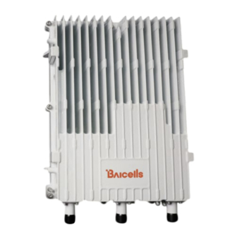
- Page 1 Aurora243 Outdoor 2x10W TDD gNodeB Installation Guide BaiBNQ_2.2-10w May 2023 Version 1.02...
- Page 2 Baicells Technologies copyrights the information in this document. No part of this document may be reproduced in any form or means without the prior written consent of Baicells Technologies. The Baicells logo is a proprietary trademark of Baicells Technologies. Other trademarks mentioned in this document belong to their owners.
- Page 3 Preliminary Release – This is the first release of the Blake Volk document Resources Documentation - Baicells product datasheets and technical manuals can be found at • Baicells.com > Resources > Documents. Support - Open a support ticket, process an RMA, and the Support Forum are at •...
- Page 4 Aurora243 Outdoor 2x10W TDD gNodeB Installation Guide Safety Information For the safety of installation personnel and the protection of the equipment from damage, please read all safety warnings. If you have any questions concerning the warnings before installing or powering on the base...
-
Page 5: Table Of Contents
3.6 Power on to Check LED Status ......................29 Initial Configuration ........................30 4.1 Configure Basic Parameters ........................ 30 4.1.2 Computer Requirements ......................31 4.1.3 Launching the Aurora243 gNB GUI ..................31 4.1.4 Upgrade Firmware ........................33 4.1.5 Configure Parameters ......................34 4.1.6 Reboot ............................ 36 4.1.7 Verify gNB Operational Status .................... - Page 6 Figure 4-6: Configure the IP address of CU ....................... 34 Figure 4-7: Configure the IP Address of DU ...................... 35 Figure 4-8 Configure the IP address of WAN Interface-Aurora243 ..............35 Figure 4-9 Configure PLMNID/Slice/TAC-Aurora243 ..................36 Figure 4-10: Reboot ............................36...
- Page 7 Aurora243 Outdoor 2x10W TDD gNodeB Installation Guide List of Tables Table 2-1: Materials ............................10 Table 2-2: Installation Tools ..........................11 Table 2-3: LEDs ..............................12 Table 2-4: Interfaces ............................12 Table 2-5: Environmental Specifications ......................13 Table 3-1: Computer Requirements ........................31...
-
Page 8: Overview
This gNB consumes low power, has a small form factor, and is easy to maintain. As a result, the Aurora243 enables operators to enhance coverage performance, improve network capacity, and eliminate blind spots for their 5G networks while reducing overall system power consumption. -
Page 9: Features
Aurora243 Outdoor 2x10W TDD gNodeB Installation Guide 1.2 Features The following is a list of key Aurora243 features. The datasheet providing technical specifications is kept up-to-date on the Baicells website. • Supports standard NR Bands N41/N48/N77/N78 • Complies with 3GPP Release 15 standards •... -
Page 10: Installation Preparation
Installation Preparation 2.1 Materials Check the Aurora243 package to ensure it contains the primary components shown in the pack out (Figure 2-1). In addition to industry-standard tools, you will need the materials described in Table 2-1 and the tools described in Table 2-2 during the installation. -
Page 11: Leds And Interfaces
Aurora243 Outdoor 2x10W TDD gNodeB Installation Guide Item Description Pole The diameter of the pole is between 40mm to 100mm of hot-galvanized steel pipe. Channel steel and equal angle steel installation are also supported. The width of the channel steel is 50mm to 100mm; the length of side of the angle steel is 63mm to 80mm... -
Page 12: Location And Environment
Aurora243 Outdoor 2x10W TDD gNodeB Installation Guide Table 2-3: LEDs Color Status Description Steady ON Power is ON Green No power supply Steady ON The power input is normal Fast flash: 0.12 s on, 0.125s off The device is powering up... -
Page 13: Grounding And Lightning Protection
Aurora243 Outdoor 2x10W TDD gNodeB Installation Guide Table 2-5: Environmental Specifications Item Description Operating Temperature -22°F to 131°F / -30°C to 55°C Storage Temperature -40°F to 149°F / -40°C to 65°C Relative Humidity (no condensation) 2% to 95% RH Atmospheric Pressure... -
Page 14: Weatherproofing
Aurora243 Outdoor 2x10W TDD gNodeB Installation Guide 2.5 Weatherproofing To protect the connection points from weather and climate, clean each connection point before installing cold shrink tubes, per the following (Figure 2-3). 1. Insert the cable into the cold shrink tube. -
Page 15: Installation
Aurora243 Outdoor 2x10W TDD gNodeB Installation Guide Installation 3.1 Process Overview Figure 3-1 provides an overview of the installation process. Figure 3-1: Installation Process Overview 3.2 Install Global Positioning System Antenna WARNING: Ensure the antenna is connected before powering up the gNB. The wireless signal transmission power can cause bodily injury and damage to the gNB and RF power amplifier devices. -
Page 16: Figure 3-2: Gps Installation Requirements
Aurora243 Outdoor 2x10W TDD gNodeB Installation Guide Figure 3-2: GPS Installation Requirements The GPS antenna system is assembled in manufacturing before packing. Therefore, the only installation step is to fix the GPS mounting bracket on the gNB with the M4*14 screws (Figure 3-3). -
Page 17: Install Gnb On Pole Or Wall
Aurora243 Outdoor 2x10W TDD gNodeB Installation Guide 3.3 Install gNB on Pole or Wall Use the following procedures to install the Aurora243 on a pole or attach to a wall. 3.3.1 Install on Pole Ensure the pole's diameter is in the range of 1.6 in–3.9 in (40 mm–100 mm), as shown in Figure 3-4. -
Page 18: Figure 3-6: Pole Or Wall Mounting Bracket
Aurora243 Outdoor 2x10W TDD gNodeB Installation Guide Figure 3-6: Pole or Wall Mounting Bracket Follow the steps below to install the Auroa243 gNB on a pole. 1. Unscrew the nuts of the pole mounting bracket, slide the two clamps to the left, and turn them up or down (Figure 3-7). -
Page 19: Figure 3-9: Attach Gnb To Bracket
Aurora243 Outdoor 2x10W TDD gNodeB Installation Guide 3. Hold the gNB vertically and align the two pins on the gNB bracket with the pin holes on the pole mounting bracket. Next, push the eNB down until the hooks are firmly attached to the corresponding slots on the pole mounting bracket (Figure 3-9). -
Page 20: Install On Wall
Aurora243 Outdoor 2x10W TDD gNodeB Installation Guide 3.3.2 Install on Wall Ensure the wall can bear at least four times the weight of the gNB. The wall mounting bracket is shown in Figure 3-11. Figure 3-11: Wall Mounting Bracket Follow the steps below to install the gNB on a wall. -
Page 21: Figure 3-14: Hang Bracket
Aurora243 Outdoor 2x10W TDD gNodeB Installation Guide 3. Hang the wall mounting bracket on the expansion bolts and fasten it with flat washers, spring washers, and nuts (Figure 3-14). Figure 3-14: Hang Bracket 4. Hold the gNB vertically and align the two pins on the gNB bracket with the pin holes on the pole mounting bracket. -
Page 22: Connect Cables
Aurora243 Outdoor 2x10W TDD gNodeB Installation Guide 3.4 Connect Cables WARNING: Ensure the antenna is connected before powering up the gNB. The wireless signal transmission power can cause bodily injury and damage to the gNB and RF power amplifier devices. -
Page 23: Connect Rf Cable(S)
Aurora243 Outdoor 2x10W TDD gNodeB Installation Guide 4. Take another cold shrink tube and pass it through the GPS jumper. 5. Connect the other end of the GPS jumper to the GPS antenna and tighten it. 6. Push the cold shrink tube to the GPS antenna joint and pull out the strip. -
Page 24: Connect Optical Fiber Cable
Aurora243 Outdoor 2x10W TDD gNodeB Installation Guide 3.4.4 Connect Optical Fiber Cable 1. Unscrew the screws on the cover of the gNB wiring cavity using a Phillips-head screwdriver to open the wiring cavity. 2. Connect the optical fiber to the OPT interface in the wiring cavity. -
Page 25: Figure 3-17: Power Adapter
Aurora243 Outdoor 2x10W TDD gNodeB Installation Guide • If the gNB and the power supply are both AC, assemble the plug according to the labels and instructions on the plug. A power adapter must be used if the gNB is DC and the power supply is AC (Figure 3-17). A •... -
Page 26: Connect Ground Cable
Aurora243 Outdoor 2x10W TDD gNodeB Installation Guide • AC Power Supply Refer to the labels on the power terminal for connecting the live, neutral, and ground wires separately to the corresponding terminals separately, and then tighten the screws. Figure 3-19: AC Power Terminal 3. -
Page 27: Figure 3-20: Pole Grounding
Aurora243 Outdoor 2x10W TDD gNodeB Installation Guide Figure 3-20: Pole Grounding 1. The installation position of the grounding bar should meet the design requirements. The holding pole and tower body must be connected to the lightning protection network or grounded with a separate lead. -
Page 28: Figure 3-21: Grounding Screws
3.4.7.2 gNB Grounding Cable Prepare the grounding cable according to the actual measurements and requirements of the specific installation site. The Aurora243 gNB has two grounding screws located on the bottom of the unit, as shown in Figure 3-21. Figure 3-21: Grounding Screws Follow the steps below to connect the ground cable. -
Page 29: Maintenance Chamber Waterproofing
2. Put the Ethernet cable on the wire and seal the wire diameter 0.28 inches ± 0.04 inches (7 mm 1 mm). ± 3.6 Power on to Check the LED Status After the Aurora243 is powered on, check that the LED indicators are lighting as expected, as described in Table 2-3 (section 2.2). -
Page 30: Initial Configuration
HaloB or SAS to verify that the new eNB unit is operational. Once it is confirmed to be operational, you can refer to the appropriate configuration guide(s) for the operating mode you plan to use. NOTE: For all GUI menus and fields, refer to the following documents on the Baicells website: Baicells.com > Resources > Documents. -
Page 31: Computer Requirements
Follow the steps below to connect to the Aurora243 gNB GUI. Connect the Aurora243 to a Personal Computer (PC) directly. Before launching the GUI, you must set up the computer’s Internet Protocol (IP) address to connect the client to the server. -
Page 32: Figure 4-2: Ip Setting On Pc
Aurora243 Outdoor 2x10W TDD gNodeB Installation Guide Click Login to enter the Aurora243 gNB GUI. The home page defaults to the Basic Setting > Basic Info menu, which reports the current gNB status. NOTE: For security reasons, you should change the password after logging in rather than leaving the default Username and Password. -
Page 33: Upgrade Firmware
Verify that the Software Version in the Basic Info pane is the most recent firmware version. Follow the steps below to upgrade to the most recent software version before configuring the gNB. 1. Download the most recent firmware file from Baicells.com > Support > Firmware, and save it on your local computer. -
Page 34: Configure Parameters
Aurora243 Outdoor 2x10W TDD gNodeB Installation Guide 4.1.5 Configure Parameters After upgrading the gNB to the recent firmware version, log in to the gNB GUI and configure related parameters to bring up the gNB online. 4.1.5.1 Configure CU and DU IP Addresses Configure the CU and DU loopback IP address as 127.0.0.X. -
Page 35: Figure 4-7: Configure The Ip Address Of Du
Configure the network-related parameters according to the actual network deployment. Go to Network > WAN/VLAN (Figure 4-8). Enter the WAN/VLAN pane and click the + Add icon to configure the IP address of the WAN interface. Figure 4-8 Configure the IP address of WAN Interface-Aurora243... -
Page 36: Reboot
Aurora243 Outdoor 2x10W TDD gNodeB Installation Guide 4.1.5.3 Configure PLMN/Slice/TAC Configure the PLMN ID/Slice/TAC related parameters according to the actual network deployment. 1. Go to NR Setting > PLMN. Under the PLMN Identity Info List, enter the PLMN menu to configure the IP address of the WAN interface. -
Page 37: Verify Gnb Operational Status
Active. Also, check that GPS Sync Status is reported as Synchronized. Figure 4-11: Verify Operational Status Before commercial deployment, Baicells recommends implementing cell site acceptance testing of a new site to ensure the service meets expectations, document network speeds at various cell locations, and... -
Page 38: Appendix: Regulatory Compliance
Aurora243 Outdoor 2x10W TDD gNodeB Installation Guide Appendix: Regulatory Compliance FCC Compliance This device complies with part 15 of the FCC Rules. Operation is subject to the following two conditions: (1) This device may not cause harmful interference, and (2) this device must accept any interference received, including interference that may cause undesired operation.
Need help?
Do you have a question about the Aurora243 and is the answer not in the manual?
Questions and answers