
Related Manuals for Baicells Atom ID0406-6.5


Summary of Contents for Baicells Atom ID0406-6.5
- Page 1 Atom ID0406-6.5 Indoor CPE User Manual BaiCE_AP_2.4.7_NA BaiCE_BG_1.6.20 December 2021 Version 1.14...
- Page 2 Internet through broadband wireless access to Long-Term Evolution (LTE) backhaul networks. The information covers how to install, configure basic settings, monitor, and perform basic maintenance and troubleshooting for the indoor CPE. If you are using a Baicells outdoor CPE, please refer to the Atom OD0406 Outdoor Low-Gain &...
- Page 3 Sharon Redfoot 16-Sep-2019 V1.7 Raasch Contact Us Baicells Technologies Co., Ltd. Baicells Technologies North America, Inc. China North America Address: 3F, Bldg. A, No. 1 Kai Tuo Rd, Haidian Dist, USA Address: 5700 Tennyson Pkwy, #300, Plano, TX Beijing, China...
-
Page 4: Table Of Contents
Table of Contents INTRODUCTION ............................... 1 FEATURES................................. 1 PARTS & MATERIALS ............................2 DESCRIPTION ..............................2 INSTALLATION ..............................4 BASIC CONFIGURATION ........................... 5 & C ........................5 OG IN HANGE ASSWORD ........................7 HECK URRENT TATUS CONS WAN S ........................... 8 ONFIGURE ETTINGS 6.3.1... - Page 5 List of Figures 1: LTE N ........................... 1 IGURE ETWORK RCHITECTURE 2: D ..............................2 IGURE IMENSIONS 3: LED & I ............................3 IGURE NTERFACES 4: I USIM C ............................4 IGURE NSERT 5: F ..............................5 IGURE IRST OGIN 6: C ............................
-
Page 6: Introduction
1 Introduction The Baicells Atom ID0406-6.5 indoor Customer Premise Equipment (CPE), aka User Equipment (UE), is part of the Baicells broadband wireless access system that integrates with Long-Term Evolution (LTE) backhaul networks to provide subscribers with Internet access. The CPE communicates through a wireless connection to the operator’s eNodeBs (eNBs) at cell sites located in the region. -
Page 7: Parts & Materials
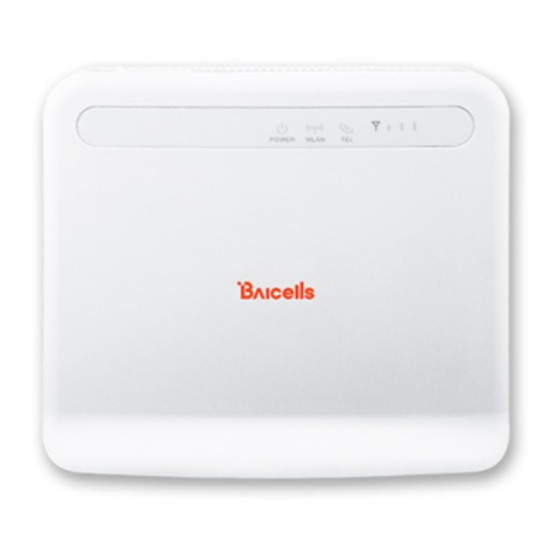
Picture Atom ID04/06-6.5 unit DC-5V Power Adaptor RJ-45 Ethernet Cable 4 Description The Baicells Atom indoor CPE is a small, compact unit that sits on a desktop, bookshelf, or other flat surface inside the building (Figure 2). Figure 2: Dimensions... -
Page 8: Figure 3: Leds & Interfaces
On the top of the unit is a card slot for the Baicells Universal Subscriber Identity Module (USIM) card provided through the operator or distributor. A USIM contains equipment and subscriber identification numbers (IMEI and IMSI) and uniquely identifies your CPE so it can access the provider's network. -
Page 9: Installation
Description Status Meaning No Ethernet connection LAN (on back) Ethernet indicator Steady on Ethernet connection is normal Blinking Ethernet data is being transmitted Table 3: Interfaces Interfaces vary by model; not all models will have all of the interfaces listed. Interfaces Description USIM... -
Page 10: Basic Configuration
2. Connect the cables (per previous Figure 3), and power on: a. LAN: Connect one end of the RJ-45 Ethernet cable to the LAN interface on the back of the unit. Connect the other end to a computer or other LAN device. b. -
Page 11: Figure 6: Change Password
Figure 6: Change Password 3. At the 4G Router login window (Figure 7), enter the default user name (admin) and your password. If you were not prompted to change the password upon initial login, enter the default password (also admin). Click on LOGIN. This will take you to the GUI home page, which is the Status > Overview window. -
Page 12: Check Current Status Icons
Figure 7: Login 6.2 Check Current Status Icons As shown in Figure 7 above, the GUI home page is the Status > Overview window. This page displays the at-a-glance CPE Current State icons at the top of the window, as shown in Figure 8. These fields give a quick indication if anything is wrong with basic CPE operation. -
Page 13: Configure Wan Settings
• Lan State - The CPE connection to the Local Area Network will be either Link Up or Link Down. If the link is down, recheck the installation steps, make sure the CPE is powered on, and check the router or other LAN device operation. •... -
Page 14: Cat4
3. Configure one or more DNS servers. The DNS translates domain names such as www.na.baicells.com into their underlying IP addresses. The service provider may use DNS servers to cache domain names frequented by its users so the sites load more quickly in a browser. -
Page 15: Figure 10: Wan Settings (Cat4)
Figure 10: WAN Settings (CAT4) -
Page 16: Cat6/7
3. For DNS Mode, you can select either Automatic or Manually. The DNS server translates domain names such as www.na.baicells.com into their underlying IP addresses. The service provider may use DNS servers to cache domain names frequented by its users so the sites load more quickly in a browser. -
Page 17: Figure 11: Wan Settings (Cat6/7)
Figure 11: WAN Settings (CAT6/7) (1 of 2) -
Page 18: Figure 12: Wan Settings (Cat6/7)
Figure 12: WAN Settings (CAT6/7) (2 of 2) -
Page 19: Table 4: Wan Settings
Table 4: WAN Settings Field Name Description Network or Operation Mode WAN Interface CAT4 only. LTE is the only option. Network Mode or CAT4: Operation Mode • NAT - Network Address Translation. Allows multiple hosts on a private network to access the Internet using a single public IP address. •... -
Page 20: Configure Wlan Settings
CPE to check after the primary DNS if the domain name was not resolved. 6.4 Configure WLAN Settings The Baicells Atom indoor CPEs have an embedded Wi-Fi access point, providing converged Wireless LAN (WLAN) and LAN interfaces into one integrated LTE service. The Wi-Fi uses 2.4 GHz unlicensed spectrum and is compliant with IEEE 802.11b/g/n. -
Page 21: Figure 13: Cat4 Wlan Settings
To set up WLAN for CAT6/7: 1. Ensure that the computer or other smart device connecting to the CPE has WLAN/Wi-Fi enabled. When the Wi-Fi LED on the unit shows “steady on”, per Table 2 LEDs, it is functional. 2. In the GUI, go to Network > WLAN Settings to enable the WiFi setting (Figure 14). 3. -
Page 22: Wifidog
NOTE 1: The feature requires a connection to an authentication server to function. NOTE 2: Wifidog is not recommended for Baicells CPEs using Power over Ethernet (PoE). You can create a whitelist to identify which website addresses or URLs users are allowed to reach. You can also limit the number of times that a user attempts to log in within a configured time period before failure to authenticate times out. - Page 23 In the GUI, go to Network > Wifidog (Figure 15 and Figure 16). For CAT4, notice the three tabs under Web Authentication Configuration - Basic Settings, Whitelist, and Advanced Settings. For CAT6/7 notice the three panes in the Wifidog Settings window - Basic Settings, Whitelist, and Advanced Settings. In the Basic Settings pane, click on the checkbox next to Enable to initiate Wifidog, and enter the AP code and the Authentication Server Address.
-
Page 24: Figure 15: Cat4 Wifidog Settings
Figure 15: CAT4 Wifidog Settings... -
Page 25: Configure Connection Mode / Connection Settings
Figure 16: CAT6/7 Wifidog Settings 6.6 Configure Connection Mode / Connection Settings You can set the CPE to connect to the default network automatically or you can connect manually, where you have to select the network you want to connect to each time. 1. -
Page 26: Figure 17: Connection Mode
Figure 17: Connection Mode 2. Manual: Click on PLMN for Public Land Mobile Network to scan all available networks and to select a specific LTE network with which to connect. Select Connect to connect to the network. Use the Disconnect button to disconnect from the selected network. NOTE: The other configuration options shown are covered in the CPE Configuration Guide. -
Page 27: Configure Scan Mode / Cell Selection
6.7 Configure Scan Mode / Cell Selection 6.7.1 Overview The Scan Mode / Cell Selection setting has to do with how the CPE selects the best wireless signal between it and an eNB for its connection to the LTE network. The setting determines which frequencies the CPE’s routine scan of available frequencies will cover. -
Page 28: Cat4
If you wish to leave the scan mode as Full Band, you do not need to make any configuration changes for the mode. The procedures for configuring the other three modes are described for CAT4 and for CAT6/7 in the sections that follow. 6.7.2 CAT4 Following are the procedures for configuring Frequency Lock, Cell Lock, and PCI Lock on a CAT4 CPE. -
Page 29: Figure 20: Cell Lock (Cat4)
• Cell Lock (Figure 20) 1. For Scan Mode, select Cell Lock from the pull-down menu. 2. Click on ADD LIST to open the Cell Lock Setting pane. 3. Select the Band number, and enter the Earfcn and PCI number combination. 4. -
Page 30: Figure 21: Pci Lock (Cat4)
• PCI Lock (Figure 21) 1. For Scan Mode, select PCI Lock from the pull-down menu. 2. Click on ADD LIST to open the PCI Lock Setting pane. 3. Enter the PCI number. 4. Click on ADD. Then click SAVE & APPLY. Figure 21: PCI Lock (CAT4) -
Page 31: Cat6/7
6.7.3 CAT6/7 Following are the procedures for configuring Dedicated EARFCN, PCI Lock, and PCI-only Lock on a CAT6/7 CPE. Dedicated EARFCN (Figure 22) • 1. For Scan Mode, select Dedicated EARFCN from the pull-down menu. 2. Identify the CPE LTE duplexing mode, TDD or FDD, and then select Apply. 3. -
Page 32: Figure 23: Pci Lock (Cat6/7)
• PCI Lock (Figure 23) 1. For Scan Mode, select PCI Lock from the pull-down menu, and click on Apply. 2. In the PCI Setting pane, select the Band number. 3. For Type, choose either EARFCN or Frequency, and enter the associated number. 4. -
Page 33: Configure Apn Management / Edit Apn Profile
APN establishes one connection between the CPE and the EPC (Evolved Packet Core) via the eNB. The Baicells CloudCore EPC, as well as eNBs operating in HaloB mode, support only one APN, which is configured by default. Therefore, when the service provider is using the Baicells CloudCore, there is no need to change this setting. -
Page 34: Configure Local Epc Apn
6.8.2 Configure Local EPC APN In a Local EPC network setup, follow the steps below to configure an APN on a CAT4 or CAT6/7 CPE. 1. In the CAT4 GUI go to LTE > APN Management, and in the CAT6/7 GUI go to LTE > Edit APN Profile (Figure 25). -
Page 35: Configure Sas
Baicells components. Refer to these documents when you are ready to implement SAS. NOTE 1: The first generation (Gen 1) Baicells CPEs do not support SAS. NOTE 2: If you are not sure if the CPE you are working with is certified, please check with your Baicells sales representative. -
Page 36: Device Information
7.1 Device Information To find basic information about the CPE you are using, in the GUI go to Status > Overview (Figure 26). At the top of the window, you can easily observe the network connection state, signal intensity, LAN state, and number of devices connected. -
Page 37: Throughput Statistics
CAT6/7) displays each configured APN gateway (Figure 29). At least one APN (APN1) is by default configured for the TR-069 connection to the Baicells CloudCore. If the service provider's network uses a Local EPC (private network EPC), there may be up to four (CAT4) or eight (CAT6/7) APNs. -
Page 38: Lan Status
Figure 29: APN Status 7.5 LAN Status The LAN Status part of the Overview window displays the Local Area Network MAC address, IP address, and Netmask (Figure 30). If you are having issues connecting to the LAN/WAN, check this window for the basic IP networking status information. -
Page 39: Devices List
7.6 Devices List To check how many devices are connected to the CPE, scroll down the Status > Overview window to the Devices List (Figure 31). If too many users are accessing the Internet through the CPE at the same time, on a CAT6/7 CPE you may consider limiting the IP address range and number of devices connected in the Security >...
Need help?
Do you have a question about the Atom ID0406-6.5 and is the answer not in the manual?
Questions and answers