
Related Manuals for Baicells Atom OD040615


Summary of Contents for Baicells Atom OD040615
- Page 1 Atom OD040615 Outdoor Low-Gain & High-Gain CPE User Manual BaiCE_AP_2.4.7_NA BaiCE_BG_1.6.20 January 2022 Version 1.12...
- Page 2 (UE). The Atom unit provides a way for users to connect to the Internet through broadband wireless access to Long-Term Evolution (LTE) backhaul networks. The information covers how to install, configure basic settings, monitor, and perform basic troubleshooting for the outdoor CPE. If you are using a Baicells indoor CPE, please refer to the Atom ID0406-6.5 Indoor CPE User Manual.
- Page 3 GUI windows as well as basic user maintenance and troubleshooting section Contact Us Baicells Technologies Co., Ltd. Baicells Technologies North America, Inc. China North America Address: 3F, Bldg. A, No. 1 Kai Tuo Rd, Haidian Address: 5700 Tennyson Pkwy., #300, Plano, TX...
-
Page 4: Table Of Contents
Table of Contents INTRODUCTION ............................... 7 FEATURES................................. 7 PARTS & MATERIALS ............................8 DESCRIPTION ..............................9 PREPARING TO INSTALL ..........................12 INSTALLATION ..............................12 BASIC CONFIGURATION ..........................20 ..............................20 OG IN ........................22 HECK URRENT TATUS CONS WAN S ......................... - Page 5 List of Figures Figure 1: LTE Network Architecture ......................7 Figure 2: Dimensions........................... 9 Figure 3: Atom OD0406 Low-Gain LEDs & Interfaces ................10 Figure 4: Atom OD0406 High-Gain LEDs & Interfaces ................10 Figure 5: Atom OD15 High-Gain LEDs & Interfaces ................... 11 Figure 6: SIM/USIM Card Atom OD0406 ....................
- Page 6 Figure 32: WAN Settings (CAT6/7/15) (2 of 2) ................... 27 Figure 33: Wifidog Settings ........................29 Figure 34: Connection Mode........................30 Figure 35: Scan Mode/Cell Selection......................31 Figure 36: Frequency Lock (CAT4) ......................32 Figure 37: Cell Lock (CAT4) ........................33 Figure 38: PCI Lock (CAT4) .........................
-
Page 7: Introduction
2 Features Some of the key features and attributes of the Atom outdoor CPEs are listed below. Exact specifications vary by model; please refer to the datasheets found at Baicells.com > Resources > Documents. • Standardized LTE TDD bands 38, 40, 41, 42, 43, 48. Customization can be requested. -
Page 8: Parts & Materials
3 Parts & Materials Table 1 lists the primary components that you should receive with the Baicells outdoor CPEs. Table 1: Parts Item Picture Atom OD0406 Low- Gain or High-Gain unit Atom OD15 unit Power Cable PoE Power Adaptor Atom OD040615... -
Page 9: Description
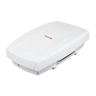
) yellow-green wire 4 Description The Baicells Atom outdoor low-gain and high-gain CPE models are powerful, standards-based devices designed to connect seamlessly to any standard LTE eNB operating on the same frequency band. The devices have a small, sleek form-factor (Figure 2) yet are ruggedized for the most challenging outdoor environments. -
Page 10: Figure 3: Atom Od0406 Low-Gain Leds & Interfaces
All models of the low-gain (Figure 3) and high-gain (Figure 4 and Figure 5) CPEs have external LED status indicator lights and interface connectors. These external features make it easier to determine the CPE's operational status and to check cables. On the low-gain CPE the LEDs are on the side of the unit, and the connection interfaces are on the bottom of the unit. -
Page 11: Figure 5: Atom Od15 High-Gain Leds & Interfaces
Figure 5: Atom OD15 High-Gain LEDs & Interfaces Table 3: LED Descriptions LEDs vary by model – not all models will have all of the LEDs listed below. Identity Description Color Status Description Reserved for future use Yellow Steady On Reserved for future use Blinking Reserved. -
Page 12: Preparing To Install
CPE so that it faces the nearest eNB. You may need to adjust the tilt and angle for optimum signal reception. If you are installing the outdoor CPE with a Baicells SNAP PoE Router, please refer to the SNAP PoE Router . -
Page 13: Figure 6: Sim/Usim Card Atom Od0406
Figure 6: SIM/USIM Card Atom OD0406 Figure 7: SIM/USIM Card Atom OD15 3. Prepare the outdoor shielded CAT5E Ethernet cable. The Ethernet cable will run between the outdoor CPE and the inside of the facility, where it will connect to the PoE adaptor and LAN. Cable length will vary by location. -
Page 14: Figure 8: Poe Adaptor Atom Od0406
Figure 8: PoE Adaptor Atom OD0406 Figure 9: PoE Adaptor Atom OD15 5. Close the waterproof cover and tighten the screws. 6. Prepare the 6 AWG (16 mm ) yellow-green ground wire and follow the ground steps below. Once the unit is fully installed, make sure the ground cable is connected to a solid ground point (earth) (Figure 10). -
Page 15: Figure 10: Completed Grounding
Figure 10: Completed Grounding a. Atom Low-Gain CPE: Connect the ground cable to the ground screw (Figure 11). NOTE: The location of the ground screw varies by model. Figure 11: Low-Gain CPE Ground Screw b. Atom High-Gain CPE: Connect the ground cable to the ground screw (Figure 12). -
Page 16: Figure 12: High-Gain Cpe Ground Screw And Ground Row
Figure 12: High-Gain CPE Ground Screw and Ground Row 7. Plug the power adaptor into an electrical outlet (Figure 13). Pay attention to the power adaptor interface directions noted on the adaptor itself. The LED indicators should light up when the unit is powered on. -
Page 17: Figure 14: Rubber Band
9. Pole installation: a. Low-Gain CPE: Attach a heavy-duty anti-slip rubber band on the pole (Figure 14). Figure 14: Rubber Band Fix the CPE bracket over the band using the hoop (Figure 15). Figure 15: Bracket Attach the CPE to the bracket and tighten the screw (Figure 16). Figure 16: Attach CPE The CPE is now ready for installation at its final outside location. -
Page 18: Figure 18: Threaded Rod
b2) Install the threaded rod onto the bracket (Figure 18). Figure 18: Threaded Rod Hold the assembly up to the pole. Attach the two omega clamps to the threaded rods with M8 nuts and tighten them (Figure 19). Figure 19: Omega Clamps The CPE is now ready for installation at its final outside location. -
Page 19: Figure 21: Fix Bracket To Wall
Figure 21: Fix Bracket to Wall a4) Attach the CPE to the bracket and tighten the screw (Figure 22). Figure 22: Attach CPE Proceed to section b. High-Gain CPE: b1) Put the bracket up to the wall and mark the drilling locations (Figure 23). Figure 23: Mark Holes for Drilling b2) Drill two 0.5 in. -
Page 20: Basic Configuration
Figure 24: Attach CPE b6) Proceed to section 11. Power on the CPE and wait a few minutes while the CPE boots up. Per Table 3, check that the LED indicators are lighting as expected. 7 Basic Configuration Reference: CPE Configuration Guide The CPE comes preloaded with a Graphical User Interface (GUI) to configure the device. -
Page 21: Figure 27: Change Password
Figure 26: Change Password 3. At the 4G Router login window (Figure 27), enter the default user name (admin) and your password. If you were not prompted to change the password upon initial login, enter the default password (also admin). Click on LOGIN. This will take you to the GUI home page, which is the Status >... -
Page 22: Check Current Status Icons
Figure 27: Login 7.2 Check Current Status Icons As shown in Figure 27 above, the GUI home page is the Status > Overview window. This page displays the at-a-glance CPE Current State icons at the top of the window, as shown in Figure 28. These fields give a quick indication if anything is wrong with basic CPE operation. -
Page 23: Configure Wan Settings
3. Configure one or more DNS servers. The DNS translates domain names such as www.na.baicells.com into their underlying IP addresses. The service provider may use DNS servers to cache domain names frequented by its users, so the sites load more quickly in a browser. -
Page 24: Figure 30: Wan Settings (Cat4)
Figure 29: WAN Settings (CAT4) -
Page 25: Cat6/7/15
3. For DNS Mode, you can select either Automatic or Manually. The DNS server translates domain names such as www.na.baicells.com into their underlying IP addresses. The service provider may use DNS servers to cache domain names frequented by its users, so the sites load more quickly in a browser. -
Page 26: Figure 31: Wan Settings (Cat6/7/15) (1 Of 2)
Figure 30: WAN Settings (CAT6/7/15) (1 of 2) - Page 27 Figure 31: WAN Settings (CAT6/7/15) (2 of 2) Table 5: WAN Settings Field Name Description Network or Operation Mode WAN Interface CAT4 only. LTE is the only option. Network Mode or CAT4: Operation Mode NAT - Network Address Translation. Allows multiple hosts on a private network •...
- Page 28 Field Name Description Tunnel - The CPE will support Layer 2 Tunneling Protocol (L2TP) or Generic • Routing Encapsulation (GRE) VPN mode. See field descriptions below*. • Bridge - The WAN port addresses will bridge to the LAN port, and the LAN port will work in trunking mode.
-
Page 29: Wifidog
NOTE 1: The feature requires a connection to an authentication server to function. NOTE 2: Wifidog is not recommended for Baicells CPEs using Power over Ethernet (PoE). You can create a whitelist to identify which website addresses or URLs users are allowed to reach. You can also limit the number of times that a user attempts to log in within a configured time period before failure to authenticate times out. -
Page 30: Configure Connection Mode / Connection Settings
7.5 Configure Connection Mode / Connection Settings You can set the CPE to connect to the default network automatically or you can connect manually, where you have to select the network you want to connect to each time. 1. In the CAT4 GUI, go to LTE > Connection Mode, and in the CAT6/7/15 GUI, go to LTE > Connection Settings to choose Automatic (CAT4)/Always On (CAT6/7/15) or Manual (Figure 33). -
Page 31: Configure Scan Mode / Cell Selection
2. Manual: Click on PLMN for Public Land Mobile Network to scan all available networks and to select a specific LTE network with which to connect. Select Connect to connect to the network. Use the Disconnect button to disconnect from the selected network. NOTE: The other configuration options shown are covered in the CPE Configuration Guide. -
Page 32: Cat4
Frequency Lock / Dedicated EARFCN – You can specify up to 9 frequencies or E-UTRA Absolute • Radio Frequency Channel Numbers (EARFCNs) the CPE will scan during its routine signal scan. The frequency/EARFCN information will come from the service provider. •... - Page 33 • Cell Lock (Figure 36) 1. For Scan Mode, select Cell Lock from the pull-down menu. 2. Click on ADD LIST to open the Cell Lock Setting pane. 3. Select the Band number, and enter the Earfcn and PCI number combination. 4.
-
Page 34: Cat6/7/15
• PCI Lock (Figure 37) 1. For Scan Mode, select PCI Lock from the pull-down menu. 2. Click on ADD LIST to open the PCI Lock Setting pane. 3. Enter the PCI number. 4. Click on ADD. Then click SAVE & APPLY. Figure 37: PCI Lock (CAT4) 7.5.3 CAT6/7/15 Following are the procedures for configuring Dedicated EARFCN, PCI Lock, and PCI-only Lock on a... - Page 35 Figure 38: Dedicated EARFCN (CAT6/7/15) PCI Lock (Figure 39) • 1. For Scan Mode, select PCI Lock from the pull-down menu, and click on Apply. 2. In the PCI Setting pane, select the Band number. 3. For Type, choose either EARFCN or Frequency, and enter the associated number. 4.
-
Page 36: Configure Apn Management / Edit Apn Profile
APN establishes one connection between the CPE and the EPC (Evolved Packet Core) via the eNB. The Baicells CloudCore EPC, as well as eNBs operating in HaloB mode, support only one APN, which is configured by default. Therefore, when the service provider is using the Baicells CloudCore, there is no need to change this setting. -
Page 37: Configure Local Epc Apn
7.7.2 Configure Local EPC APN In a Local EPC network setup, follow the steps below to configure an APN on a CAT4 or CAT6/7/15 CPE. 1. In the CAT4 GUI go to LTE > APN Management, and in the CAT6/7/15 GUI go to LTE > Edit APN Profile (Figure 41). -
Page 38: Configure Sas
Baicells components. Refer to these documents when you are ready to implement SAS. NOTE 1: The first generation (Gen 1) Baicells CPEs do not support SAS. NOTE 2: If you are not sure if the CPE you are working with is certified, please check with your Baicells sales representative. -
Page 39: Basic Troubleshooting
8 Basic Troubleshooting References: CPE Configuration Guide Some of the common GUI menus and fields used for monitoring and troubleshooting the CPE are covered in this section. Features and GUI navigation may vary by CPE model and software version. 8.1 Device Information To find basic information about the CPE you are using, in the GUI go to Status >... -
Page 40: Throughput Statistics
CAT6/7/15) displays each configured APN gateway (Figure 45). At least one APN (APN1) is by default configured for the TR-069 connection to the Baicells CloudCore. If the service provider's network uses a Local EPC (private network EPC), there may be up to four (CAT4) or eight (CAT6/7/15) APNs. It shows Mainly you want to check that any gateways you are using show as enabled. -
Page 41: Lan Status
Figure 45: APN Status 8.5 LAN Status The LAN Status part of the Overview window displays the Local Area Network MAC address, IP address, and Netmask (Figure 46). If you are having issues connecting to the LAN/WAN, check this window for the basic IP networking status information. -
Page 42: Devices List
8.6 Devices List To check how many devices are connected to the CPE, scroll down the Status > Overview window to the Devices List (Figure 47). If too many users are accessing the Internet through the CPE at the same time, on a CAT6/7/15 CPE you may consider limiting the IP address range and number of devices connected in the Security >...
Need help?
Do you have a question about the Atom OD040615 and is the answer not in the manual?
Questions and answers