Table of Contents
Advertisement
Quick Links
AZUR™ PUMP 72C160
Equipment references
64350160130000 - 64350160131101
64350160131111 - 64350160135111
64350160131175-64350160131115 - 64350160134115
User Manual 582109110
2023-09-08
Index I
Translation of the original instructions
SAMES KREMLIN SAS
13 Chemin de Malacher
38240 Meylan
www.sames-kremlin.com
33 (0)4 76 41 60 60
Advertisement
Table of Contents

Related Manuals for SAMES KREMLIN AZUR 72C160


Summary of Contents for SAMES KREMLIN AZUR 72C160
- Page 1 AZUR™ PUMP 72C160 Equipment references 64350160130000 - 64350160131101 64350160131111 - 64350160135111 64350160131175-64350160131115 - 64350160134115 User Manual 582109110 2023-09-08 Index I Translation of the original instructions SAMES KREMLIN SAS 13 Chemin de Malacher 38240 Meylan www.sames-kremlin.com 33 (0)4 76 41 60 60...
- Page 2 Any communication or reproduction of this document, in any form whatsoever, and any exploitation or communication of its contents is prohibited, except with the express written consent of SAMES KREMLIN. The descriptions and features contained in this document are subject to change without notice.
-
Page 3: Table Of Contents
Contents Evolution table of the document ..........................6 Guarantee ..................................7 SAFETY INSTRUCTIONS ..........................8 ............................8 ERSONAL SAFETY Overview ..................................8 Meaning of the pictograms ............................9 Security devices ................................. 10 Danger of Pressure ..............................10 Injection hazards ................................ 11 Fire hazards, explosion, electric arc, static electricity .................... - Page 4 ........................44 ECHNICAL CHARACTERISTICS ........................... 47 RINCIPLE OF OPERATION INSTALLATION ............................49 Connections subsets ..............................49 Connection to compressed air supply........................50 ..............................51 TORAGE .............................. 51 ANDLING COMMISSIONING ........................... 52 USE OF EQUIPMENT ..........................53 10.1 ............................53 SER SETTINGS 10.2 ..........................
- Page 5 SPARE PARTS ............................205 17.1 7000 120 ......................205 OTOR ODEL STROKE 17.2 C160 ........................211 LUID SECTION ODEL Repair kit .................................. 213 Fluid section seal kit # 144 050 402 ......................... 214 Fluid section seal kit # 144 050 403 ......................... 215 Fluid section seal kit # 144 050 404 .........................
-
Page 6: Evolution Table Of The Document
Evolution table of the document Recording revisions Editor Object Revision Date Modified by E DUMONT/F AIRLESS pump A - Draft - Week 21/2019 N Plantard SEGUIN beta test F SEGUIN AIRLESS pump Week 09/2020 N Plantard F SEGUIN AIRLESS pump Week 09/2020 N Plantard F SEGUIN... -
Page 7: Guarantee
The warranty excludes wear parts, deterioration or wear resulting from abnormal or unscheduled use by SAMES KREMLIN, failure to observe instructions for proper operation or lack of maintenance. The warranty is limited to the repair or exchange of parts returned to our factory and recognized as defective by us and does not cover the listed wear parts or not. -
Page 8: Safety Instructions
It must be used only for the purpose for which it was intended. Do not modify or transform the material. Parts and accessories must only be supplied or approved by SAMES KREMLIN. The equipment must be checked periodically. Defective or worn parts must be replaced. -
Page 9: Meaning Of The Pictograms
Safety instructions Meaning of the pictograms Danger pinching, Danger : high Danger moving parts Risks of product crushin pressure emanation Danger : hot parts or Danger : flammability Risk of explosion Danger : electricity surfaces risks Danger (user) Gloves required Warning Danger Grounding Mandatory... -
Page 10: Security Devices
Safety instructions Security devices Attention Guards (motor cover, coupling guard, housings, ...) are set up for safe use of the equipment. The manufacturer can not be held responsible for any bodily injury as well as failures and / or damage to the equipment resulting from the destruction, the occultation or the total or partial removal of the protectors. -
Page 11: Injection Hazards
Safety instructions Injection hazards "HIGH PRESSURE" technology requires the utmost care. Operation can cause dangerous leaks. There is a risk of product injection into exposed parts of the body, which can lead to serious injury and the risk of amputation: An injection of product into the skin or other parts of the body (eyes, fingers ...) must be treated urgently by appropriate medical care. -
Page 12: Hazards Of Toxic Products
Safety instructions Hazards of toxic products Toxic products or vapors can cause serious injury through contact with the body, in the eyes, under the skin, but also by ingestion or inhalation. It is imperative : To know the type of product used and the dangers it represents, Store the products to be used in appropriate areas, Contain the product used in the application in a container... -
Page 13: Integrity Of The Material
Safety instructions 1.2 Integrity of the material Material recommendations Protectors are put in place for safe use of the equipment. Exemples : Engine hood. Carters. The manufacturer can not be held responsible in case of: Bodily injury. As well as breakdowns and / or damage to the equipment resulting from the destruction, the occultation or the total or partial withdrawal of the protectors. - Page 14 It is forbidden to disassemble the safety valve during the operation of the pump - check that the air regulator and pressure gauge are working once a month. Only use genuine SAMES KREMLIN accessories and spare parts designed to withstand the pump's operating pressures.
- Page 15 Safety instructions Paint phase pump and pressure gun Mandatory wearing of PPE during this phase of painting where the pump and the gun are under pressure. Do not look at the gun nozzle when it is under pressure. Rinse at a maximum of 1 bar at the pressure gauge of the air equipment (variable pressure depending on the length of the pipes).
- Page 16 Safety instructions Hoses Recommendations for hoses. Keep hoses away from traffic areas, moving parts and hot areas. Never subject product hoses to temperatures above 60 ° C or below 0 ° C. Do not use hoses to pull or move equipment. Tighten all connections and hoses and connectors before commissioning the equipment.
-
Page 17: Products Implemented
Given the diversity of the products implemented by the users and the impossibility of listing all the characteristics of the chemical substances, their interactions and their evolution over time SAMES KREMLIN can not be held responsible: The poor compatibility of materials in contact. -
Page 18: Environment
Environment 2 Environment The equipment must be installed on a horizontal, stable and flat ground (eg concrete slab). Non-moving equipment must be secured by suitable fixing devices (spit, screws, bolts, etc.) to ensure its stability during use. To avoid risks due to static electricity, the equipment and its components must be grounded. - Page 19 Environment Do not store more flammable products than necessary inside the work area. These products must be stored in approved containers and grounded. Use only grounded metal buckets for the use of rinse solvents. Cartons and papers are to be banned. Indeed they are very bad conductors, even insulators.
-
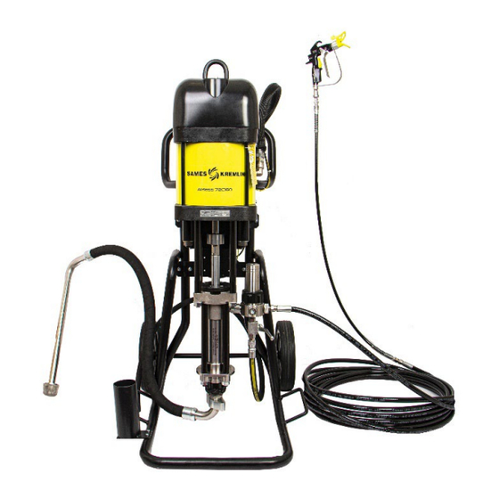
Page 20: Presentation Of The Material
Presentation of the material 3 Presentation of the material 3.1 Complete system 3.1.1 Generic presentation visual Descrption Azur™ Pump Hose Suction rod Bucket Filter Cart... -
Page 21: Table Of Azur™Airless® Pump And Package Codes
Presentation of the material 3.1.2 Table of Azur™Airless® pump and package codes Airless Assembling Suction hose Working regulator Output Sflow™ Part number pressure Wall Hose Hose Gravity Fluid filter 3/8 + Bare Cart (bar) mounted 600 mm 1000 mm hopper pressure 1.6m 64350160130000... -
Page 22: Visuals Of The Proposed Configuration
Presentation of the material 3.1.3 Visuals of the proposed configuration Azur™ Pump 72C160 - 64350160130000 Wall mounted Azur™ pump 72C160 + Air supply + Suction rod L600 - 64350160131101 Wall mounted Azur™ pump 72C160 + Air supply + Wall mounted Azur™ pump 72C160 + Air Filter + Suction rod L1000 + Filter - 64350160135111 supply + Filter + Suction rod L1000 - 64350160131111... -
Page 23: Context Of Use
Presentation of the material Azur™ Pump 72C160 + Air supply, Cart, Suction Wall mounted Azur™ pump 72C160 + Air rod L600, TE assembly, Valve, Drain - supply + Cart + Suction rod L600 + Filter - 64350160131175 64350160131115 Azur™ Pump 72C160 + Air supply + Cart + Hopper + Filter - 64350160134115 Context of use AZUR™AIRLESS®... -
Page 24: Description Of The Main Elements Of The System
Presentation of the material 3.2 Description of the main elements of the system Pump 72C160 Expected use These pumps, coupled with air motors, are designed to transfer or spray different liquid or pasty products with a desired flow rate and outlet pressure. -
Page 25: Motor 146371000 7000 Stroke 120
7000 Stroke 120 Expected use This Pneumatic motor is intended to be coupled to the fluid section systems recommended by SAMES KREMLIN in order to obtain the ratio and the expected flow rate. Functional description Double-acting pneumatic piston motor. Rectilinear reciprocating... - Page 26 Presentation of the material Adjustment The increase of the motor supply air pressure (via the air regulator) leads to an increase of the number of pump piston returns/mn (cycles) which leads to a flow rate increase and to an outlet pressure increase of the pumped material.
- Page 27 Presentation of the material Switch set Chamber + rod assembly Carter + distributor...
-
Page 28: Seals Kits Fluid Section C160
Presentation of the material Seals kits fluid section C160 Seals kits O-rings Upper packing Lower packing (statics) 144050412 PTFE + LEATHER PTFE 4x PTFE+ 4x LEATHER 3x PTFE + 3x LEATHER 144050413 UHMWPE + PTFE PTFE 4x UHMWPE + 4x LEATHER 3x UHMWPE + 3x LEATHER 144050414 UHMWPE + LEATHER PTFE... -
Page 29: Criteria For Choosing A Seals Kit
Presentation of the material Criteria for choosing a seals kit Seal package Choice Selection Criterias Composition Chemical Mechanical Temperature Comment Compatiblity Resistance up to 60°c (abrasivity) 144050412 PTFE / Leather Good chemical compatibility. Ideal for abrasive material & preximed 2K material. -
Page 30: Identification
Identification 4 Identification 4.1 Description of the label marking Principles Paint pumps are designed to be installed in a paint booth. This equipment complies with the following provisions: ATEX Directive (2014/34 / EU: II 2 G - Group II, Category 2, Gas). - Page 31 X: Special conditions apply for safe use. Refer to the requirements in the instruction manuals accompanying this product. Pompe / Pump Model of the pump REF. Pump reference Number given by SAMES KREMLIN. SERIES The first 2 digits indicate the year of manufacture MAX. PRES. (BAR/PSI) PROD Maximum product pressure...
-
Page 32: Principle Of Codification
Principle of codification 5 Principle of codification 5.1 Pump codification PUMP CODIFICATION X X X X Motor and hydraulic type Pump stand 0:None 6435 1:Wall mounted 5: Heavy duty cart Fluid section 0225 Pump Output 0160 0: None Fluid section material 1: with filter SST 2: with filter SST + 2 outputs* Inox: 1... -
Page 33: Codification Packs
Principle of codification 5.2 Codification packs PACK LIGHT CODIFICATION Pack range Gun type 0: None Airless : 3 5: SFlow™reversible tip 519 Pump selection Whip end hose 52225 0: None 72160 1: 1m Polyamid 1/4'' - 1/4 NPSM* Seal pack 2: 1.6m Polyamid 1/4'' - 1/4 NPSM PTFE + Leather: 2 UHMWPE + PTFE: 3... -
Page 34: Equipment Plans
Equipment plans 6 Equipment plans Pump 72C160... -
Page 35: Wall Mounted Pump
Equipment plans Wall mounted pump... -
Page 36: Pump 72C160 + Cart
Equipment plans Pump 72C160 + Cart... -
Page 37: Pump 72C160 + Cart + Hopper
Equipment plans Pump 72C160 + Cart + Hopper... -
Page 38: Fluid Section C160
Equipment plans Fluid section C160... -
Page 39: Motor 7000 Stroke 120
Equipment plans Motor 7000 Stroke 120... -
Page 40: Air Supply
Equipment plans Air supply... -
Page 41: Filter
Equipment plans Filter... -
Page 42: Pump Priming Kit
Equipment plans Pump priming kit... -
Page 43: Hopper
Equipment plans Hopper... -
Page 44: Technical Specifications And Operating Principles
Technical specifications and operating principles 7 Technical specifications and operating principles 7.1 Technical characteristics Pump 72C160 Theoretical weight Type of pump 72C160 Weight Naked 46.6 kg / 102.7 lbs Wall mounted + Suction rod + air supply, without filter 60.4 kg / 133.2 lbs Wall mounted + Suction rod + air supply +filter 64.2 kg / 141.5 lbs Cart + Suction rod + air supply +filter... - Page 45 Technical specifications and operating principles MOTOR 7000 - STROKE 120 - 146371000 Motor type: 7000-120 Motor stroke : 120 mm Motor section : 484 cm² Weight : 35 kgs / 77.17 lbs...
- Page 46 Technical specifications and operating principles Fluid section C160 Fluid section C160 characteristics Fluid section C160: 67.5 cm² Volume of product delivered per cycle: 160 cc Number of cycles per liter of product: 6.25 Flow rate at 20 cycles: 3.2 C160 Sealing gasket Fixed end: 8 chevron seals (4 UHMWPE + 4 PTFE or 4 PTFE + 4 UHMWPE or 4 UHMWPE + 4 PTFE G) Inf.
-
Page 47: Principle Of Operation
Technical specifications and operating principles 7.2 Principle of operation Pump The pump includes: A reciprocating air motor. A fluid section (mechanically linked to the engine. The motor is supplied with compressed air. In its reciprocating movement, the motor drives the piston of the fluid section, the paint is sucked up and is forced back under pressure. - Page 48 The inversion system is carried out via: two switches, A 5/2 bistable distributor, A 4/2 bistable distributor. These pneumatic motors are intended to be coupled to the fluid section systems recommended by SAMES KREMLIN to obtain the ratio and the expected flow rate.
-
Page 49: Installation
These fluid sections are intended to be coupled to pneumatic motors compatible stroke. It is imperative to comply with a motor / fluid section combination provided by SAMES KREMLIN. Grounding Coupled with a pneumatic motor, the fluid section will be grounded via the earth cable of this motor. -
Page 50: Connection To Compressed Air Supply
Installation If earth continuity is not assured, check terminal, wire, bracket, and grounding point. Never operate the pump without having solved this problem. Connection to compressed air supply Set the pressure at the air regulator. For proper operation and long life of the engine, the supply air must be filtered and not lubricated (see §... -
Page 51: Storage
Installation 8.1 Storage Pump Place the equipment away from moisture after closing the various air inlets and various openings (plugs). Storage before installation: Storage ambient temperature: 0°C/+50° C / 32°F/122° F. Protect the unit against dust, water runoff, moisture and shocks. -
Page 52: Commissioning
Commissioning 9 Commissioning Pump The pumps are tested in our workshops with lubricant. Prior to start-up, this lubricant must be removed by rinsing with a suitable solvent. At the end of the day, rinse with a suitable solvent. It is advisable to stop the fluid section in the "low inversion" position in order to prevent the product from catching on the piston rod. -
Page 53: Use Of Equipment
Use of equipment 10 Use of equipment 10.1 User settings Pump Before commissioning, fill the cup with lubricant "T". Motor Note: the motor is wired in direct control. Start pressure about 500 grams. 10.2 Safety in production Guards (motor cover, coupling guard, housings, ...) are set up for safe use of the equipment. -
Page 54: Recommended Range Of Use
Use of equipment 10.3 Recommended range of use This design does not allow the use of the pump in paint recirculation system : transitory zone to achieve higher pressure : never stay on this zone while operation – up to 0.3Br Long operation on this zone will generate material leakage on the cup lub Vert... -
Page 55: Diagnostic Help / Troubleshooting Guide
Use of equipment 10.4 Diagnostic help / Troubleshooting guide Troubleshooting Before any intervention on a pump, it is imperative to carry out a general procedure of decompression and purge. In order to avoid the risk of personal injury, product injections, injuries caused by moving parts or arcing, it is essential to follow the following procedure before any intervention during system shutdown, assembly, cleaning or changing the nozzle. - Page 56 Use of equipment To minimize ice build-up: Use an air dryer, coalescing filter or desiccant filter to lower the water vapor content of the air. Raise the compressed air temperature. Warmer air going in helps the motor parts stay above 0°c / 32°F. Compressed air, especially at these volumes, is warm when compressed.
-
Page 57: Possible Symptoms Of Faults / Causes Of Faults / Remedy To Be Applied - Fast Operation
Use of equipment 10.5 Possible symptoms of faults / Causes of faults / Remedy to be applied - fast operation Possible symptoms of faults / Causes / Remedies Fluid section part Defaults Possible causes Remedies Leakage at the upper fluid Insufficient tightening of the Tighten the packing nut. - Page 58 Use of equipment Defaults Possible causes Remedies The piston goes down The pump is badly filled Check the parameters of use of the quickly (single effect accessories (on follower plate or suction operation) rod). These may be poorly adapted or obstructed.
-
Page 59: Possible Symptoms Of Faults / Causes / Remedies Motor Part
Use of equipment Possible symptoms of faults / Causes / Remedies Motor part Perform a decompression procedure before any intervention: shut off the air supply with the pressure relief valve in order to evacuate residual air from the engine, decompress the circuit produced by opening the purge valve of the pump or the gun. -
Page 60: Maintenance
Maintenance 11 Maintenance 11.1 Preventive Maintenance Plan Attention Before any intervention, it is imperative to follow the decompression procedure and the safety instructions. During prolonged shutdown, stop the pump when the piston is in the down position. Fluid section part Daily Detect leaks at connections. - Page 61 Maintenance Twice a month If the lubricant is strongly colored in the cup, renew it. Check that the cup remains clean and clean it regularly with solvent after draining the lubricant. Once a month Check that the air regulator and pressure gauge are working properly. Every year Disassemble the fluid section fully.
-
Page 62: Motor Part
The tightening of the components. The condition of the muffler (s). The fixing of the hood. The correct operation of the safety valve. The state of the decompression valve. SAMES KREMLIN recommends changing the motor muffler foams every year. Instruction Designation Reference... -
Page 63: Preventive Maintenance
Maintenance This maintenance consists of replacing parts with cuts or wear and cleaning organs with compatible products without using abrasive materials that could damage them. The O-rings are mounted with special "pneumatic" grease. Make sure that none of them get damaged; cutting one of them may cause the engine to malfunction. -
Page 64: Disassembly / Reassembly Operation
Disassembly / Reassembly Operation 12 Disassembly / Reassembly Operation Attention Before any intervention, it is imperative to follow the decompression procedure and the safety instructions. 12.1 Disassembly Disassembly of the grounding cable Hold the grounding terminal with a 10 mm spanner and unscrew the upper nut with the other key. -
Page 65: Preliminary Operations
Disassembly / Reassembly Operation Preliminary operations Option If the pump is equipped with air equipment: turn off the air supply with the valve (1). Unscrew the air supply hose (2) with a 32 mm spanner, blocking the air inlet fitting (3) with a 27 mm spanner. Tools needed... - Page 66 Disassembly / Reassembly Operation Remove the 2 screws with a 6 mm BTR wrench and then the washers from the motor cover. Tools needed...
- Page 67 Disassembly / Reassembly Operation Remove the motor hood.
- Page 68 Disassembly / Reassembly Operation If it is necessary to change the switches, first remove the pneumatic hoses manually. Note: Locate hoses for reassembly.
- Page 69 Disassembly / Reassembly Operation Remove the 4 screws with a 3 mm BTR wrench and then the washers (1). Manually remove the connectors (2) and switches (3). Remove the 2 screws (5) with a BTR wrench of 3 mm. Manually remove the distributor (4) Tools needed...
-
Page 70: Disconnect The Motor And The Fluid Section
Disassembly / Reassembly Operation 12.2 Disconnect the motor and the fluid section Using a flat screwdriver, disengage the axle brake (1) from the groove above the locking ring (2), in order to release it. Tools needed... - Page 71 Disassembly / Reassembly Operation Manually lift the locking ring (1) and manually remove the coupling nuts (2) underneath.
- Page 72 Disassembly / Reassembly Operation Using a 24 mm wrench, unscrew the 4 nuts connecting the flange to the tie rods and remove the 4 washers. Attention: Support the fluid section well (Fluid section weight: 11 kg / 24.25 lbs). Tools needed...
- Page 73 Disassembly / Reassembly Operation Separate the motor from thefluid section and retrieve the closing ring.
- Page 74 Disassembly / Reassembly Operation If the motor is mounted on a support, unscrew the two nuts with a 27 mm wrench and remove the two washers from the handles under the lower flange. Tools needed...
- Page 75 Disassembly / Reassembly Operation If the engine hood has not been removed in the previous steps, remove the engine hood with a BTR wrench of 6 mm by removing the two screws and washers. Tools needed...
- Page 76 Disassembly / Reassembly Operation Sling on the lifting ring / bracket. Tools needed...
- Page 77 Disassembly / Reassembly Operation Place the engine on a horizontal plane using a bridge or a stem. Tools needed...
- Page 78 Disassembly / Reassembly Operation Retract the motor shaft manually.
- Page 79 Disassembly / Reassembly Operation Remove the 4 tie rods with a 19 mm wrench. Tools needed...
- Page 80 Disassembly / Reassembly Operation In the event of disassembly of the lower bearing (change of seals), unscrew the 4 screws with a BTR wrench of 5 Manually remove the lower bearing along the motor shaft. Tools needed...
- Page 81 Disassembly / Reassembly Operation Using a flat screwdriver, replace the seals (1) and (2). Tools needed...
- Page 82 Disassembly / Reassembly Operation Attention Manually maintain pressure on the sheet metal (1) before unscrewing the 4 screws. Remove the 4 screws with a 6 mm BTR wrench and the washers from the housing grid. Tools needed...
- Page 83 Disassembly / Reassembly Operation Remove the crankcase and protective foam from the motor.
- Page 84 Disassembly / Reassembly Operation Remove the pneumatic hoses from the distributor, leaving the bulkheads.
- Page 85 Disassembly / Reassembly Operation Remove the 4 rigid foams and their holders from the distributor.
- Page 86 Disassembly / Reassembly Operation Remove the 4 screws above and below the housing using a BTR wrench of 4 mm. Tools needed...
- Page 87 Disassembly / Reassembly Operation Remove the 4 screws connecting the distributor to the housing, using a BTR wrench of 6 mm. Tools needed...
- Page 88 Disassembly / Reassembly Operation Remove the two exhaust mounts.
- Page 89 Disassembly / Reassembly Operation If necessary, place the distributor assembly on a workbench for disassembly.
- Page 90 Disassembly / Reassembly Operation To dismantle the distributor, remove the 4 screws using a BTR wrench of 6 mm. Seal (A) is sold with the distributor. Tools needed...
- Page 91 Disassembly / Reassembly Operation Disassembly of the safety valve requires a spanner of 20 mm. Disassembly of the 2.7 / 4 pipe fittings requires a 10 mm spanner. Tools needed...
- Page 92 Disassembly / Reassembly Operation Remove the flat gaskets, as well as the plastic sheet with the assembled bulkheads.
- Page 93 Disassembly / Reassembly Operation (A) If necessary, manually retract the motor rod to adjust its position.
- Page 94 Disassembly / Reassembly Operation To unscrew the cam, hold the rod (1) with an 8 mm BTR wrench. Unscrew the screw (3) with an 8 mm BTR wrench and manually remove the cam (4). 8 x2 Tools needed...
- Page 95 Disassembly / Reassembly Operation Using the slings, approach the motor in a vertical position above a suitable vice. Attention in vertical position, the motor rod falls down by gravity. Tools needed...
- Page 96 Disassembly / Reassembly Operation Remove the motor from the vice, so that the lower flange rests on the jaws of the vice and the rod is locked in the jaws. Attention If the vice does not have a soft jaw, use a cloth to avoid damaging the rod coating.
- Page 97 Disassembly / Reassembly Operation Remove the bracket with the switches and the 5/2 bistable distributor, unscrewing the two screws at its base with a 10 mm open-end wrench Tools needed...
- Page 98 Disassembly / Reassembly Operation Attention: it is strongly discouraged to remove the caliper, the tightening torque required for its installation being very high.
- Page 99 Disassembly / Reassembly Operation To change the seals, disassemble the upper bearing by removing the 4 screws with a BTR key of 5 mm. Tools needed...
- Page 100 Disassembly / Reassembly Operation Using a flat screwdriver, change the seals (1) and (2) Tools needed...
- Page 101 Disassembly / Reassembly Operation Successively release each rod from the motor, holding the top nut (1) with a 19 mm socket wrench, while removing the corresponding bottom nut and washer assembly (2) with the other wrench. Attention: be careful not to do the opposite operation that causes the stems to fall at the same time.
- Page 102 Disassembly / Reassembly Operation Remove the 4 rods from the motor. Note: Note the mounting direction of the flange before removing it. Tools needed...
- Page 103 Disassembly / Reassembly Operation Remove the top flange of the motor by locating its position. Tools needed...
- Page 104 Disassembly / Reassembly Operation To replace the seal (1) of the upper flange of the motor, remove it manually using a flat screwdriver. Tools needed...
- Page 105 Disassembly / Reassembly Operation Loosen the vice and remove the rod and motor piston assembly. Note: it is normal for the seal to float in the piston groove between the piston and the cylinder. Tools needed...
- Page 106 Disassembly / Reassembly Operation Retrieve the piston seal. Tools needed...
- Page 107 Disassembly / Reassembly Operation To replace the stem seal, first unscrew the 6 screws with a BTR key of 6 mm, to remove the two upper and two lower flanges. Note: mark the mounting direction of the counter flanges. Tools needed...
- Page 108 Disassembly / Reassembly Operation Remove the piston (1), and then remove the seal (2) using a flat screwdriver. Tools needed...
- Page 109 Disassembly / Reassembly Operation Manually remove the cylinder from the lower flange. Tools needed...
- Page 110 Disassembly / Reassembly Operation Remove the gasket from the lower flange using a flat screwdriver. Tools needed...
- Page 111 Disassembly / Reassembly Operation Attention: never disassemble the plate of firm of the equipment present on the lower flange.
-
Page 112: Reassembly
Disassembly / Reassembly Operation 12.3 Reassembly ATTENTION: The procedure described below requires the use of a vice and a workbench. Place seals (1) and (2) in their respective locations on the motor bearing. Grease the entire joint contour evenly with industrial ... - Page 113 Disassembly / Reassembly Operation Place the engine bearing fitted with greased seals in each of the two flanges. Screw the 4 screws connecting each bearing to the corresponding flange (upper and lower), using a BTR key of 5 mm. Tools needed...
- Page 114 Disassembly / Reassembly Operation Fit the gasket on the flange and lubricate evenly over the entire joint contour with the industrial grease. Tools needed Kluber petamo HY 133N...
- Page 115 Disassembly / Reassembly Operation Place and insert with a mallet the motor cylinder on the lower flange. The cylinder must come into abutment on the flange. Grease the inside of the cylinder evenly over the entire contour. Tools needed Kluber petamo HY 133N...
- Page 116 Disassembly / Reassembly Operation Place the motor rod (lower part) in a V-jaw vice (protect this rod so as not to damage it). Attention If the vice does not have a soft jaw, use a cloth to avoid damaging the rod coating. Tools needed...
- Page 117 Disassembly / Reassembly Operation Place the seal on the motor rod. Grease the seal. Tools needed Kluber petamo HY 133N...
- Page 118 Disassembly / Reassembly Operation Push the drive piston onto the motor rod (1) and place this piston between the two grooves (2) of the rod. It must cover the seal. Tools needed...
- Page 119 Disassembly / Reassembly Operation Place the counter flanges (2 and 4) and glue them in the grooves (1) of the drive rod (pay attention to the direction), Screw and glue (anaerobic adhesive low threadlock) the 6 screws CHC M8X45 (3) with a key BTR of 6 mm. Wipe off excess glue.
- Page 120 Disassembly / Reassembly Operation Place the floating seal in the groove of the motor piston. Then lubricate it evenly over the entire contour. Note: It is normal for the seal to float in the piston groove between the piston and the cylinder. Tools needed Kluber petamo HY 133N...
- Page 121 Disassembly / Reassembly Operation Undo the vice, lift and place the rod and piston assembly on a bench. Tools needed...
- Page 122 Disassembly / Reassembly Operation Place the lower flange and power cylinder assembly on the open vise by positioning the rod over the vise crosshead. Tools needed...
- Page 123 Disassembly / Reassembly Operation Take up the rod and piston assembly with the lifting means through the lifting eye, Evenly grease entire height circumference. Tools needed Kluber petamo HY 133N...
- Page 124 Disassembly / Reassembly Operation From above, position the rod (1) in the bronze bearing (2) of the motor bearing and SLOWLY lower the rod + piston assembly. Tools needed...
- Page 125 Disassembly / Reassembly Operation Gently bring the floating seal (1) of the rod and piston assembly into contact with the upper edge (2) of the cylinder. Tools needed...
- Page 126 Disassembly / Reassembly Operation Place the seal in the motor cylinder by guiding it manually along the entire contour of the cylinder. Attention Risk of pinching Tools needed...
- Page 127 Disassembly / Reassembly Operation Lower the rod and piston assembly to the stop on the lower flange of the motor or vice. Tools needed...
- Page 128 Disassembly / Reassembly Operation Place and fit with a mallet the upper flange equipped (with stirrup), until the stop. (Attention to the direction of assembly). Tools needed...
- Page 129 Disassembly / Reassembly Operation Place the 4 tie rods + nut on the motor, from above, and on the lower part, place the washers + nut on the tie rods. Tools needed...
- Page 130 Disassembly / Reassembly Operation MANUALLY tighten the nuts (1) as far as they will go. Tools needed...
- Page 131 Disassembly / Reassembly Operation Tighten the cam (2) with the CHC M10 screw (1), with a BTR key of 8 mm, and counterblock on the flat part of the rod with a BTR wrench of 8 mm. 8 x2 Tools needed...
- Page 132 Disassembly / Reassembly Operation In the case (not recommended) where the bracket has been removed, reinstall the bracket with the 2 CHC M18 screws, using a 14 mm BTR torque wrench with a torque of 260 N.m.. BTR14 Tools needed...
- Page 133 Disassembly / Reassembly Operation In the case where the bracket has been dismounted, reinstall it on the motor by fixing the two screws located at its base using a spanner or a pipe wrench of 10 mm. Tools needed...
- Page 134 Disassembly / Reassembly Operation Fix the two switch sensors (3) on the bracket by placing the washers and tightening the 4 screws (1) and the connections (2) with a BTR key of 3 mm. Tools needed...
- Page 135 Disassembly / Reassembly Operation Remove motor unit horizontal plane (established type), using a lifting device hooked to the caliper. Tools needed...
- Page 136 Disassembly / Reassembly Operation Manually re-enter the motor shaft.
- Page 137 Disassembly / Reassembly Operation Install the tie rods using a 19 mm torque wrench with a tightening torque of 100 N.m. Pay attention to the tightening torque. Tools needed...
- Page 138 Disassembly / Reassembly Operation If the bulkheads are not mounted on the plastic sheet: Screw all the partition passes and onto the plastic sheet.
- Page 139 Disassembly / Reassembly Operation If the base with the connections is completely disassembled: Mount the 2 pipe connectors 2.7 / 4 on the base with a 10 mm spanner. Fit the 90 ° elbow on the base with a flat wrench of 13 mm and orient it according to the image below (image).
- Page 140 Disassembly / Reassembly Operation Glue (with sealing tube glue) and screw the power supply with the elbow fitting with a 27 mm spanner. Glue (with glue the sealed tube) and screw the assembly on the fitting. Tighten with a 27 mm spanner (using connection), and put in the up position.
- Page 141 Disassembly / Reassembly Operation Place in the foam (1) support rigid foam (2). Screw the 2 screws CHC M8 the previous subassembly on the exhaust support, with a 6 mm BTR key (x2). Repeat the previous two steps on the other side of the exhaust bracket (4).
- Page 142 Disassembly / Reassembly Operation Place the 2 previous sub-assemblies on the equipped base, with the 4 screws CHC M8.
- Page 143 Disassembly / Reassembly Operation Stabilize the plastic plate of the housing on the vise, to facilitate the work of fixing the joints. Place the two base seals (between the plastic plate and the base). Attention Be sure to grease the joints sufficiently to promote adhesion to the substrate.
- Page 144 Disassembly / Reassembly Operation Using a 4 mm BTR wrench, attach the distributor assembly to the plastic sheet with the 4 screws. Tools needed...
- Page 145 Disassembly / Reassembly Operation Place the two other base seals (1), on the outside of the plastic sheet of the housing, by passing them in the screws (2). Grease the seals. Tools needed Kluber petamo HY 133N...
- Page 146 Disassembly / Reassembly Operation Move the assembly to the motor flanges, and screw the 4 screws CHC M8 with a 6 mm BTR key. Note: Check the tightness so that there is no daylight at the seals. Tools needed...
- Page 147 Disassembly / Reassembly Operation Make the pneumatic wiring of the distributor part.
- Page 148 Disassembly / Reassembly Operation Wall bracket option Screw both daggers with a 27 mm torque wrench with a tightening torque of 260 Nm on the lower flange. Tools needed...
- Page 149 Disassembly / Reassembly Operation Using a 19 mm torque wrench, tighten the 4 nuts of the tie rods with a tightening torque of 100 N.m Tools needed...
- Page 150 Disassembly / Reassembly Operation Place the foam and the grid, by putting the 4 washers and the 4 screws CHC M8 with a key BTR of 6 mm. Attention Manually maintain pressure on the plate (1) to tighten the 4 screws. Tools needed...
- Page 151 Disassembly / Reassembly Operation Make the pneumatic wiring of the upper part.
- Page 152 Disassembly / Reassembly Operation Place the cover and washers by screwing in the CHC M8 screws with a 6 mm BTR wrench. Tools needed...
- Page 153 Disassembly / Reassembly Operation Wall bracket option With lifting means: Place the assembly on the support (option) and screw the 2 nuts + washers, 27 mm torque wrench with a tightening torque of 100 N.m. Tools needed...
- Page 154 Disassembly / Reassembly Operation Reinstall the grounding cable with a wrench of 10 mm. Tools needed...
- Page 155 Disassembly / Reassembly Operation Place the axle brake and the locking ring along the motor shaft. Make the coupling of the motor to the fluid section. Note: It is important to perform this operation vertically. Attention: Support the fluid section well (Fluid section weight: 11 kg / 24.25 lbs).
- Page 156 Disassembly / Reassembly Operation Put the fluid section back in place, by manually screwing the 4 M16 nuts in contact. Coupling to the fluid section. Connecting the Air supply. Run the pump slowly at no load for 3 cycles to align the pump seals vertically.
-
Page 157: Pneumatic Wiring
Pneumatic Wiring 13 Pneumatic Wiring Count cycles pneumatic (A) Remove the plug (1) from the fitting on the left side of the pump (in front view). (B) Connect a 4/6 hose (2) to the coupling on one end and to the metering equipment on the other end. -
Page 158: Fit The Regulator
Pneumatic Wiring Fit the regulator Install the regulator of the air equipment, respecting the direction of assembly: the direction of air circulation is given by the arrow (1). -
Page 159: Direct Air Control
Pneumatic Wiring Direct air control Install the side pipe along the motor cylinder, passing through the bulkhead from the crankcase on one side, and the lower flange of the motor on the other hand. Connect the direct pilot hose to the fitting below the regulator. -
Page 160: Indirect Air Control
Pneumatic Wiring Indirect air control... -
Page 161: Filter
Filter 14 Filter Install filter Observe the direction of the arrows (1) for circulation of the product. Note: The filter can be mounted in the up or down position. In this manual it is shown in the lower position. -
Page 162: Orientation Of The Product Output
Filter Orientation of the product output (A) By default, the filter (1) is installed to the right of the pump (front view). (B) and (C) It is possible to change the position of the product output by first removing the 4 nuts and washers to disconnect the fluid section part (on which the filter is mounted) of the motor Note: (B) possible if hopper is missing. -
Page 163: Connecting A Second Gun
Filter Connecting a second gun (A) To install a second spray gun on the filter, first remove the cap, with a 14 mm BTR wrench, located on the filter base. (B) Glue and screw the connection with a 32 mm open- end wrench to the empty location. -
Page 164: Reversing The Direction Of The Tank
Filter Reversing the direction of the tank (A) Remove the valve (1) from the filter with a 21 mm spanner and the cap (2) using a BTR key of 8. (B) Using a flat wrench of 27, rotate the filter by 180 °. (C) Install the valve (1) at the other end of the filter by turning it 180 °;... - Page 165 Filter To disassemble the filter. Place the integral key (1) against the corresponding projections on the filter ring (2). Unscrew the ring (2) and remove the filter to access the filter elements (3) to change them. Tools needed...
-
Page 166: Operations Dismantling / Reassembling The C160 Fluid Section
Operations Dismantling / Reassembling the C160 Fluid section 15 Operations Dismantling / Reassembling the C160 Fluid section Drain the pump, cane or hopper. Solvent the recirculating pump with solvent, using the filter valve and the 1.5 m hose (option), and drain the pump. - Page 167 Operations Dismantling / Reassembling the C160 Fluid section Stop the pump in the low position. Fluid section rod in low position...
-
Page 168: Desassembly
Operations Dismantling / Reassembling the C160 Fluid section 15.1 Desassembly Change the upper seals (8 chevrons + PTFE O-ring): Release the axle brake (1) from the groove above the locking ring (2), to disengage the coupling nuts (3). Remove the 4 nuts with a 24 mm open-end wrench. Disconnect the motor from the fluid section (uncoupling phase). - Page 169 Operations Dismantling / Reassembling the C160 Fluid section With the regulator Put the motor rod in the up position With the valve Close the valve (1). ...
- Page 170 Operations Dismantling / Reassembling the C160 Fluid section Remove the cover.
- Page 171 Operations Dismantling / Reassembling the C160 Fluid section Unscrew the 4 screws CHC (1) with a key BTR of 6 mm. Remove the flange (2) manually. Tools needed...
- Page 172 Operations Dismantling / Reassembling the C160 Fluid section With a flat screwdriver in the groove of the cartridge body (1), remove the cartridge (1), spring cartridge (2), spring (3) + male seal press (4) + 8 V-seals (5 and 6)) + adjustment wedges (8), positioning it.
- Page 173 Operations Dismantling / Reassembling the C160 Fluid section With suction cane option: Remove the suction rod with a mallet, keeping it at the elbow. With hopper option: Unscrew the knurled nut manually by a few millimetres. Unscrew the nut from the fitting with a 55 mm ...
- Page 174 Operations Dismantling / Reassembling the C160 Fluid section Disassembly of the pump hopper assembly to access the suction valve: Unscrew the knurled nut (1) manually by a few millimetres. Unscrew the nut from the fitting (2) with a 55 mm wrench. Rotate the hopper (3) to access the suction valve.
-
Page 175: Clean And / Or Replace The Ball + Carbide Seat With Rod Option
Operations Dismantling / Reassembling the C160 Fluid section Clean and / or replace the ball + carbide seat with rod option If cleaning and or replacement ball + seat carbide with option rod With the filter key (1): Unscrew the nut from the pump foot (2), And, Pull out the assembly (2) from the bottom. -
Page 176: Cleaning The Carbide Seat And Changing The Seal
Operations Dismantling / Reassembling the C160 Fluid section Cleaning the carbide seat and changing the seal Clean the carbide seat (1) with a solvent-soaked cloth. To change the seal (2) Remove the seal with a flat screwdriver and replace it. To change the carbide seat (1): Replace the entire assembly. - Page 177 Operations Dismantling / Reassembling the C160 Fluid section Unscrew all the filter part (option) with a 27 mm open- end wrench (unscrew at the fitting). Tools needed...
- Page 178 Operations Dismantling / Reassembling the C160 Fluid section Disengage the axle brake (1) above the locking ring (2) and disengage the coupling nuts (3). Unscrew the 4 nuts and the washers with a spanner of 24 Attention: Good support fluid section (fluid section weight: 11 kg / 24.25 lbs).
- Page 179 Operations Dismantling / Reassembling the C160 Fluid section Manually remove the cover.
- Page 180 Operations Dismantling / Reassembling the C160 Fluid section Manually: Position the fluid section assembly in the jaws of the vice, in horizontal position, at the tie rods(1). (Weight of the fluid section unit = 11 kg / 24.25 lbs). Put martyr's wedges (2) and tighten the vice ...
- Page 181 Operations Dismantling / Reassembling the C160 Fluid section To remove the pump foot: Unscrew the nut with the filter key (1) Remove the assembly (2) and the ball (3). Tools needed...
- Page 182 Operations Dismantling / Reassembling the C160 Fluid section Unscrew the 4 nuts with a spanner of 24 mm open-end wrench and the washers. Tools needed...
- Page 183 Operations Dismantling / Reassembling the C160 Fluid section With a mallet, remove the valve body with snap ring. Tools needed...
- Page 184 Operations Dismantling / Reassembling the C160 Fluid section In case of disassembly stop ring Manually, press the snap ring out of its seat and change the workpiece. In case of change position of the snap ring Manually, press the snap ring out of its seat and change position.
- Page 185 Operations Dismantling / Reassembling the C160 Fluid section In case of no prior change of the upper joints Unscrew the 4 screws CHC with a key BTR of 6 mm. Remove the flange manually. Remove (Cartridge + spring cartridge + spring + press male seal + 8 V seals) with a flat screwdriver, positioning it in the groove of the cartridge body.
- Page 186 Operations Dismantling / Reassembling the C160 Fluid section If change of seals Position the piston in the jaws of the vise at the flats of part. Tools needed...
- Page 187 Operations Dismantling / Reassembling the C160 Fluid section With a flat wrench: Unscrew the discharge valve at the flats part of the piston fitted. Change the seals by replacing them with new ones (grease). If change of the pin Position the piston in the jaws of the vice at the flats of the discharge valve.
- Page 188 Operations Dismantling / Reassembling the C160 Fluid section In case of replacement of the pin Replace the pin with a new one, holding it with a mallet. Depending on the viscosity of the product and if the lifting of the ball is greater: Replace the pin L=30 mm with pin L=28 mm or ...
- Page 189 Operations Dismantling / Reassembling the C160 Fluid section When changing the seal 909420311 (between flange) Extract the seal with a flat screwdriver. Then replace a new gasket and grease the gasket on the contour more evenly. Manually remove the product cylinder. To remove the cylinder (presence of paint): tap with the mallet ...
-
Page 190: Reassembly
Operations Dismantling / Reassembling the C160 Fluid section 15.2 Reassembly Replace together the 4 lower spacers (27) and the new seals (24 and 25) (grease), Position the pin in the flap. Put the ball in place Screw the discharge valve manually onto the flat surface of the equipped piston. - Page 191 Operations Dismantling / Reassembling the C160 Fluid section Grease the inside of the cylinder, Place the equipped piston and seat assembly in the fluid cylinder (discharge valve first), Push the flats (1) of the discharge valve out of the cylinder, Secure the stem with a 24 mm open-end wrench, and tighten the discharge valve to 150 Nm with a 32 mm torque wrench.
- Page 192 Operations Dismantling / Reassembling the C160 Fluid section Reassemble the rod in the produced cylinder using a mallet, respecting the above dimension. Tools needed...
- Page 193 Operations Dismantling / Reassembling the C160 Fluid section Manually position the O-rings in the flange. Grease the seals. Tools needed Kluber petamo HY 133N...
- Page 194 Operations Dismantling / Reassembling the C160 Fluid section Insert the fluid cylinder into the flange.
- Page 195 Operations Dismantling / Reassembling the C160 Fluid section Screw the 4 tie rods with a 19 mm torque wrench to the 100 N.m. torque. Tools needed...
- Page 196 Operations Dismantling / Reassembling the C160 Fluid section Manually press the locking ring (2) into its seat at the desired height. Manually place the O-ring (1) and grease. Tools needed Kluber petamo HY 133N...
- Page 197 Operations Dismantling / Reassembling the C160 Fluid section Use a mallet to insert the valve body with the locking ring. Tools needed...
- Page 198 Operations Dismantling / Reassembling the C160 Fluid section Insert the washers. Screw the 4 nuts with a 24 mm torque wrench to the 100 N.m. torque. Tools needed...
- Page 199 Operations Dismantling / Reassembling the C160 Fluid section Manually place the ball (3), Screw on the nut with the wrench (1), Loosen the key (1) with a mallet. Tools needed...
- Page 200 Operations Dismantling / Reassembling the C160 Fluid section Stack the seals (5 and 6) and the 4 spacers (7) between the parts (2 and 4). Grease the rafter joints inside and outside. Place the rafter piece seal assembly (spring cartridge - male seal press) into the cartridge (1).
- Page 201 Operations Dismantling / Reassembling the C160 Fluid section Manually place the flange. crew the 4 CHC screws together with a 6 mm BTR wrench. Tools needed...
- Page 202 Operations Dismantling / Reassembling the C160 Fluid section Put the cover on.
- Page 203 Operations Dismantling / Reassembling the C160 Fluid section Position the fluid section under the motor. Position the washers and tighten the nuts manually. Manually lift the motor rod. Position the axle brake (1) and locking ring (2) on the motor rod.
-
Page 204: Installation Of The Wall Pump
Installation of the wall pump 16 Installation of the wall pump The wall mounting procedure is carried out via a lifting device. Sling on the pallet, the pump assembly and wall bracket with lifting means, by the motor ring. Present the pump and support assembly on the wall or metal frame. -
Page 205: Spare Parts
Spare parts 17 Spare parts Use only genuine SAMES KREMLIN accessories and spare parts designed to withstand the pump's operating pressures. 17.1 Motor, Model 7000 stroke 120... - Page 206 Spare parts # Reference Description 930 151 198 Screw CHc M 8x16 963 020 019 Washer ZU 8 146 371 010 Cover 901 180 024 Grounding terminal equipped 146 371 008 U-bolt 930 151 507 Screw CHc M 18x40 88 189 Screw CHc M 10x30 209 364 933 151 196...
- Page 207 Spare parts...
- Page 208 Spare parts...
- Page 209 Spare parts # Reference Designation 209 358 Bracket 88 131 Screw HM 6x12 151 800 002 Switch (x 2) 963 040 012 Washer MU 4 933 151 273 Screw CHc M 4x20 905 120 983 Elbow MF T 2x4 934 081 332 Screw Hc M 6x25 905 120 910 Crossing of partition...
- Page 210 Spare parts # Reference Description 88 153 Screw CHc M 8x30 146 371 005 Socket 552 251 Fitting 1/8 "G 146 371 015 Bracket 91 424 Distributor 5/2 932 151 326 Screw CHc M 3x25 # Reference Description 146 371 040 Motor seals kit (ind 11 (x 2), 12 (x 2), 17 (x 2), 22, 24 (x 2) 41 (x 4)) * Recommended maintenance parts.
-
Page 211: Fluid Section, Model C160
Spare parts 17.2 Fluid section, Model C160 Ref. Fluid section 144050402 144050403 144050404 144050405... - Page 212 Spare parts # Reference Description 144 050 038 Cover 930 151 500 Screw CHc M 8x40 144 050 041 Flange 144 050 042 Cartridge 150 319 701 Spring 144 050 032 Spring housing 144 050 037 Male joint clamp 144 050 027 Assembled material piston 144 050 025 ...
-
Page 213: Repair Kit
Spare parts Repair kit # References Description 144 050 160 Repair kit C160 150 319 701 Spring 144 050 040 Discharge valve 907 414 244 Ball Ø 16 stainless steel 144 050 017 Female joint clamp 144 050 037 ... -
Page 214: Fluid Section Seal Kit # 144 050 402
Spare parts Fluid section seal kit # 144 050 402 # Reference Description 144 050 412 Pack of seals NC / NS Chevron seal, UHMWPE NC / NS Chevron seal, PTFE 144 050 034 Adjustment wedge 909 420 311 ... -
Page 215: Fluid Section Seal Kit # 144 050 403
Spare parts Fluid section seal kit # 144 050 403 # Reference Description 144 050 413 Pack of seals NC / NS Chevron seal, UHMWPE NC / NS Chevron seal, PTFE 144 050 034 Adjustment wedge 909 420 311 ... -
Page 216: Fluid Section Seal Kit # 144 050 404
Spare parts Fluid section seal kit # 144 050 404 # Reference Description 144 050 414 Pack of seals N.C. / N.S. Chevron seal, UHMWPE N.C. / N.S. Chevron seal, leather 144 050 034 Adjustment wedge 909 420 311 ... -
Page 217: Fluid Section Seal Kit # 144 050 405
Spare parts Fluid section seal kit # 144 050 405 # Reference Description 144 050 415 Pack of seals N.C. / N.S. Chevron seal, UHMWPE N.C. / N.S. Chevron seal, PTFE G 144 050 034 Adjustment wedge 909 420 311 ... -
Page 218: Spare Parts - Product Filter 3/4 ", Model 500 Bar / 7252 Psi
Spare parts 17.3 Spare Parts - Product Filter 3/4 ", Model 500 bar / 7252 psi... - Page 219 Spare parts Filter equipped # Reference Description 155 581 456 Bare stainless steel filter 500 bar 000 161 115 No. 15 screen (360 μm) N.C. / N.S. Socket G3 / 4 " 055 581 420 Loose nut R3/4" 905 210 304 Cap 3/8 NPT Stainless steel 906 333 105 Chemical Nickel Gas Cap3/4 "...
- Page 220 Spare parts Option Ind. / Pos. 2 # Reference Description 000 161 101 Screen n ° 1 (37 μ) 000 161 102 Screen n ° 2 (77 μ) 000 161 104 Screen n° 4 (99 µ) 000 161 106 Screen n° 6 (168 µ)* 000 161 108 Screen n°...
- Page 221 Spare parts Ind. / Pos. 3 # Reference Description 055 490 020 Non-return valve MF 3/4'' G 151 590 012 Priming kit (without filter) for 3/8'' hoses 907 414 703 Ceramic ball Ø16 907 414 705 Ceramic ball Ø30 907 414 342 Carbide ball Ø16 907 414 343 Carbide ball Ø30...
-
Page 222: Accessories
Spare parts Accessories Ind. / Pos. 16 # Reference Description 149 030 017 Wrenching wrench Ind. 17 # Reference Description 151 590 105 Air supply 903 130 517 Regulator 903 130 518 Regulator nut... - Page 223 Spare parts Ind. 18 Ind. 19 Ind. 22 # Reference Description 149 597 200 Suction rod 1''1/4 L=600 150 104 106 Straight fitting M 1''1/4 G – M 2'' G 149 597 250 Suction rod 1''1/4 L=1000 149 596 153 Strainer for suction rod (2000 µ)
- Page 224 Spare parts Ind. 20 # Reference Description 150 104 106 Straight fitting M 1"1/4G M 2 "G for rod 2".- stainless steel 250 bar / 3626 psi 144 050 052 Straight fitting MM 1"1/4G 150 104 151 Straight fitting MM 1/4" NPSM – stainless steel 500 bar / 7252 psi 150 104 152 Straight fitting MM 3/8"...
- Page 225 Spare parts Ind.23 Ind.27 # Reference Description 151 590 700 Cart 151 590 565 Cart handle + screws 056 100 199 Mounting bracket with bracket Ind.24 # Reference Description Hopper 20L assembly F 1" 1/4" + MM 1" 1/4 125 010 000...
- Page 226 Spare parts Ind.25 # Reference Description 156 160 040 Heater, model MAGMA 500 DI9 230V 3500W M 1/2 JIC (refer to doc 582.104.110) 156 160 050 Heater, model MAGMA 500 DI9 115V 1800W M 1/2 JIC (refer to doc 582.104.110) 156 160 060 Heater, model MAGMA 500 DI9 400V 3800W M 1/2 JIC (refer to doc 582.104.110)
- Page 227 Spare parts Ind.26 # Reference Description 151 590 016 Kit Sprayer 135 745 449 Airless spray gun Sflow 450 bar / 6526 psi (refer to doc 582.094.110) 050 500 207 Hose PA 15M 3/8'' NPSM - 500 bar / 7252 psi 905 210 516 ...
- Page 228 Spare parts GUN FILTER (x 4) Material Mesh Color 129 740 081 Stainless steel 200 mesh/ 74µ 04-XX 06-XX 129 740 181 PA 129 740 082 Stainless steel 150 mesh / 100µ Blue 06-XX 12-XX 129 740 182 PA 129 740 083 Stainless steel 100 mesh / 149µ...
- Page 229 Spare parts CHART - REVERSING TIPS Angle 30° 40° 50° 60° 70° 80° 90° ø Water flow rate orifice Pump Handle (L/min) at XXX bar (pouc filter Filter e / ”) Number Fan width (MESH) (MESH) (cm) at / 16 / 21 / 24.5 / 29...
-
Page 230: Hoses Codification
Spare parts Hoses codification HOSES CODIFICATION 050 XXX Working pressure Hose lenght 1: 0.5 m / 19.68" 350B : 350 2: 1 m / 39.37" 500B : 500 3: 1.6 m / 63" 4: 3 m / 118.1" 5: 7.5 m / 295.3" Diameter 6: 10 m / 393.7"... -
Page 231: Hoses 350 Bar / 5076 Psi
Spare parts Hoses 350 bar / 5076 psi Maximum working pressure 350 / 5076 (bar) / (psi) Material PTFE Fitting A and B (Lock nut) 1/4 NPSM 3/8 NPSM 1/2 NPSM 1/4 NPSM 3/8 NPSM 1/2 NPSM Ø inside " "... -
Page 232: Hoses 500 Bar / 7252 Psi
Spare parts Hoses 500 bar / 7252 psi Maximum working pressure 500 / 7252 (bar) / (psi) Material PTFE Fitting A and B (Lock nut) 1/4 NPSM 3/8 NPSM 1/2 NPSM 1/4 NPSM 3/8 NPSM 1/2 NPSM Ø inside " "... -
Page 233: Appendices
Appendices 18 Appendices 18.1 Déclaration EU and UKCA of incorporation Refer to the existing declaration delivered with the product. -
Page 234: Declaration Of Conformity
Declaration of Conformity 19 Declaration of Conformity The manufacturer: SAMES KREMLIN with assets of 12 720 000 Euros Head office : 13, chemin de Malacher - 38 240 - MEYLAN - FRANCE Tel. 33 (0)4 76 41 60 60 Herewith declares that the sub-assembly Pump 72C160 with part numbers: 3.72160.3.1.7.15.2.5...
Need help?
Do you have a question about the AZUR 72C160 and is the answer not in the manual?
Questions and answers