Chapters
Table of Contents

Subscribe to Our Youtube Channel
Related Manuals for SAMES KREMLIN 20F50


Summary of Contents for SAMES KREMLIN 20F50
- Page 1 PUMP 20F50 pH Equipment reference 151772200 User Manual 582156110 2020-11-20 Index C Translation from the original instructions SAMES KREMLIN SAS 13 Chemin de Malacher 38240 Meylan www.sames-kremlin.com 33 (0)4 76 41 60 60...
- Page 2 Any communication or reproduction of this document, in any form whatsoever, and any exploitation or communication of its contents is prohibited, except with the express written consent of SAMES KREMLIN. The descriptions and features contained in this document are subject to change without notice.
-
Page 3: Table Of Contents
Fluid filter 3/8", model 250 bar / 3625.75 psi ......................28 IDENTIFICATION ..........................29 ......................29 ESCRIPTION OF THE LABEL MARKING EQUIPMENT PLANS ..........................31 Pump, model 20F50 pH (bare pump and wall mounted pump) ................31 TECHNICAL FEATURES AND OPERATING PRINCIPLES ................33 ..........................33 ECHNICAL FEATURES ..........................37 PERATING PRINCIPLE INSTALLATION ............................. - Page 4 Servicing kit # 144 951 095 ............................167 Package of seals # 144 951 090 ..........................168 14.5 ..........................170 IR SUPPLY ASSEMBLY 14.6 1/4" ..........................172 IR REGULATOR 14.7 3/8 ", / 3625.75 ..................176 LUID FILTER MODEL 20/11/2020 582156110-EN-indC-Pump-20F50 pH.docx...
-
Page 5: Evolution Table Of The Document
Recording revisions Editor Object Revision Date Modified by C. HUSSON Pump, Week 32/2020 B. KHALDI model 20F50 pH C. HUSSON – Disassembly / Week 42/2020 F. SEGUIN reassembly added C. HUSSON Update Week 47/2020 C. HUSSON Dear customer, you have just purchased your new equipment and we thank you for it. -
Page 6: Guarantee
The warranty excludes wear parts, deterioration or wear resulting from abnormal or unscheduled use by SAMES KREMLIN, failure to observe instructions for proper operation or lack of maintenance. The warranty is limited to the repair or exchange of parts returned to our factory and recognized as defective by us and does not cover the listed wear parts. -
Page 7: Declaration Of Conformity
1 Declaration of Conformity Refer to the existing declaration delivered with the product. 582156110-EN-indC-Pump-20F50 pH.docx 20/11/2020... -
Page 8: Declaration Of Incorporation
2 Declaration of incorporation The manufacturer : SAMES KREMLIN with assets of 12 720 000 Euros Head office chemin Malacher - 38 240 - MEYLAN - FRANCE Tel. 33 (0)4 76 41 60 60 Herewith declares that the pump, model 20F50 pH, part number :... -
Page 9: Safety Instructions
It must be used only for the purpose for which it was intended. Do not modify or transform the equipment. Parts and accessories must only be supplied or approved by SAMES KREMLIN. The equipment must be checked periodically. Defective or worn parts must be replaced. -
Page 10: Meaning Of The Pictograms
Refer to the Grounding manual/instruction Gloves must be worn General obligation leaflet Mandatory respiratory Safety footwear Protective helmet Hearing protection protection Wearing of glasses is Protective visor Protective clothing Material recycling mandatory 20/11/2020 582156110-EN-indC-Pump-20F50 pH.docx... -
Page 11: Security Devices
Also, a fluid drain valve must be installed in the fluid system so that the fluid can be drained (after shutting off motor air and decompressing it) before any intervention on the equipment. These valves must remain closed for air and open for the product during the intervention. 582156110-EN-indC-Pump-20F50 pH.docx 20/11/2020... -
Page 12: Injection Hazards
(refer to product safety data sheets). to equip the drums with a lid to reduce the diffusion of gases and vapors in the cabin. it is forbidden to pump explosive materials. 20/11/2020 582156110-EN-indC-Pump-20F50 pH.docx... -
Page 13: Toxic Chemicals Hazards
Attention The use of halogenated hydrocarbon solvents and products containing these solvents in the presence of aluminum or zinc is prohibited. Failure to follow these instructions could result in an explosion hazard causing serious injury or death. 582156110-EN-indC-Pump-20F50 pH.docx 20/11/2020... -
Page 14: Integrity Of The Material
Housings. The manufacturer cannot be held responsible in case of: bodily injury, as well as breakdowns and / or damage to equipment resulting from the destruction, hiding or total or partial removal of guards. 20/11/2020 582156110-EN-indC-Pump-20F50 pH.docx... - Page 15 - check the correct functioning of the air regulator and the pressure gauge once a month. Use only genuine SAMES KREMLIN accessories and spare parts designed to withstand the operating pressure of the pump. Pump feeding phase ...
- Page 16 Wearing of PPE is mandatory. Risk of fluid section heating during defusing Risk of overheating of the fluid section in case of defusing. Ground cable It is mandatory to ground the pump. The rods are conductive. 20/11/2020 582156110-EN-indC-Pump-20F50 pH.docx...
- Page 17 To make a normal stop: Use the air regulator to gradually depressurize the pump. Emergency shut-off valve The stop valve is an emergency stop valve. This valve must be within easy reach of the operator. 582156110-EN-indC-Pump-20F50 pH.docx 20/11/2020...
- Page 18 It will determine the risks of immediate reactions or reactions due to repeated exposures to personnel. SAMES KREMLIN declines any responsibility, in case of: Physical or mental injury, Direct or indirect material damage due to the use of chemical substances.
-
Page 19: Environment
These materials must be stored in approved, grounded containers. Use only grounded metal pails for flushing solvents. Cardboard and papers are to be banned. They are very bad conductors, even insulators. 582156110-EN-indC-Pump-20F50 pH.docx 20/11/2020... - Page 20 Follow the rules in your locality and do not dispose of your old appliances with your household waste. Proper disposal of this old appliance will help prevent negative effects on the environment and human health. 20/11/2020 582156110-EN-indC-Pump-20F50 pH.docx...
-
Page 21: Presentation Of The Material
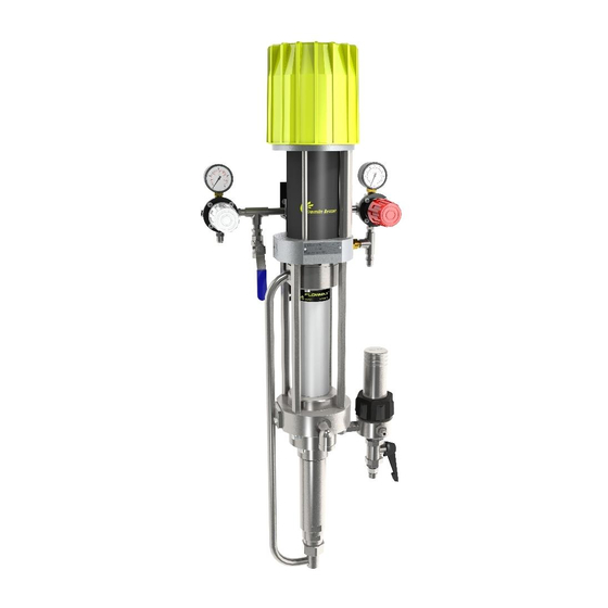
Discharge valve Air motor Suction rod Fluid section Fluid filter ‘AIR MOTOR’ air regulator Drain valve Gauge Drain rod ‘GUN AIR’ air regulator HP fluid hose Gauge Spray gun Air inlet valve Air hose (static conductor) Ground 582156110-EN-indC-Pump-20F50 pH.docx 20/11/2020... -
Page 22: Context Of Use
Context of use The pump, model 20F50 pH is designed to meet the required performance and lifetime requirements: Air operated piston pump (stainless steel) – with a bellows seal fluid packing, Low maintenance and ease of use. Use without lubrication. -
Page 23: Description Of The Main Elements Of The System
5.2 Description of the main elements of the system Pump, model 20F50 pH Expected use The pump is recommended for water-based or solvent-based paints whose viscosity is lower than 1000 mPa/s. The pump consists of a motor, model 500-4 and a fluid section, model F50 pH. -
Page 24: Motor, Model 500-4 Stroke 100
Motor, model 500-4 Stroke 100 Expected use This air motor is intended to be coupled to the fluid section systems recommended by SAMES KREMLIN in order to obtain the ratio and the expected flow rate. Functional description Reciprocating air motor. - Page 25 (cycles) which leads to a flow rate increase and to an outlet pressure increase of the pumped material. AIR CONSUMPTION OF THE MOTOR Pressure of the motor at 6 bar / 87 psi Type 500-4 582156110-EN-indC-Pump-20F50 pH.docx 20/11/2020...
-
Page 26: Fluid Section, Model F50 Ph
Fluid section, model F50 pH Seals kits Fixed packing Upper Lower Part number packing packing O-rings Bellows (statics) 144 951 090 PTFE + PE PTFE Seats : carbide, Balls : ceramics. 20/11/2020 582156110-EN-indC-Pump-20F50 pH.docx... -
Page 27: Air Supply Assembly
Air supply assembly 582156110-EN-indC-Pump-20F50 pH.docx 20/11/2020... -
Page 28: Fluid Filter 3/8", Model 250 Bar / 3625.75 Psi
Fluid filter 3/8", model 250 bar / 3625.75 psi 20/11/2020 582156110-EN-indC-Pump-20F50 pH.docx... -
Page 29: Identification
This equipment complies with the following provisions: ATEX Directive (2014/34 / EU : II 2 G - group II, category 2, gas). The EU declaration of conformity is included in the packaging of the pump, 20F50 pH. 582156110-EN-indC-Pump-20F50 pH.docx 20/11/2020... - Page 30 Description Sigle SAMES KREMLIN Manufacturer’s identification CE : European conformity : Use in explosive area II : group II 2 : category 2 Surface material intended for an environment in which explosive II 2 G atmospheres due to gases, vapors, mists are likely to occasionally occur during normal operation.
-
Page 31: Equipment Plans
7 Equipment plans Pump, model 20F50 pH (bare pump and wall mounted pump) 582156110-EN-indC-Pump-20F50 pH.docx 20/11/2020... - Page 32 20/11/2020 582156110-EN-indC-Pump-20F50 pH.docx...
-
Page 33: Technical Features And Operating Principles
8 Technical features and operating principles 8.1 Technical features Pump, model 20F50 pH Theoretical weight Type of pump, model 20F50 pH Weight Wall mounted + suction rod + air supply +filter 24 kg / 52.9 lbs Theoretical pressure ratio 20/1 - maximum fluid pressure: 120 bar / 1740 psi Maximum operating temperature ... - Page 34 : Ø 16 mm iD / 5/8" dia Air hose (between "GUN AIR" regulator and gun) : Ø 7 mm ID / 1/4" dia. AIRMIX fluid hose (between pump fluid outlet and gun) : Ø 4.8 mm ID. / 3.16" dia. 20/11/2020 582156110-EN-indC-Pump-20F50 pH.docx...
- Page 35 Motor, model 500-4 - STROKE 100 Motor features : 500-4 Motor stroke : 100 mm / 4" Motor section : 50 cm² / 7.7 sq.in 582156110-EN-indC-Pump-20F50 pH.docx 20/11/2020...
- Page 36 Number of cycles : 20 per L / 76 per gal Fluid flow rate (30 cycles) : 1.5 L/mn / 0.4 US gal Sealing gasket : Fixed : PTFE static O-rings and PE bellows, Upper : PE seal, Lower : PE seal. 20/11/2020 582156110-EN-indC-Pump-20F50 pH.docx...
-
Page 37: Operating Principle
Therefore, to adjust the fluid flow rate, turn the phosphorus knob. to adjust the spray air, turn the black knob. The pump is a FLOWMAX® one (with bellows). 582156110-EN-indC-Pump-20F50 pH.docx 20/11/2020... - Page 38 It is therefore necessary to connect the fluid section to earth via the motor ground cable (refer to motor instructions for grounding). Never place your hand on the suction port of the pump. The suction power may cause serious injury. 20/11/2020 582156110-EN-indC-Pump-20F50 pH.docx...
- Page 39 The reversing system is carried out by means of a reversing block. These pneumatic motors are intended to be coupled to the fluid sections recommended by SAMES KREMLIN in order to obtain the ratio and the expected flow rate. 582156110-EN-indC-Pump-20F50 pH.docx...
-
Page 40: Installation
These fluid sections are intended to be coupled to pneumatic motors of compatible stroke. It is imperative to comply with a motor / fluid section combination provided by SAMES KREMLIN. Grounding Coupled with a pneumatic motor, the fluid section will be grounded via the earth cable of this motor. -
Page 41: Connection To Compressed Air Supply
1 bar / 14.5 psi for a few minutes. Proceed as follows: Couple the motor with the fluid section, Connect the main air supply to the motor. 582156110-EN-indC-Pump-20F50 pH.docx 20/11/2020... -
Page 42: Storage
Protect the unit against dust, water runoff, moisture and shocks. Storage after installation: Protect the unit against dust, water runoff, moisture and shocks. 9.2 Handling Pump Pumps and fluid sections of significant weight and size must be handled with appropriate means. 20/11/2020 582156110-EN-indC-Pump-20F50 pH.docx... -
Page 43: Start Up
1 bar / 14.5 psi for a few minutes. Proceed as follows: Couple the motor with the fluid section, Connect the main air supply to the motor. Adjust the pressure at the air regulator. 582156110-EN-indC-Pump-20F50 pH.docx 20/11/2020... -
Page 44: Use Of The Equipment
...) are set up for safe use of the equipment. The manufacturer cannot be held responsible in case of bodily injury as well as breakdowns and / or damage of the material resulting from the destruction, hiding or total or partial removal of guards. 20/11/2020 582156110-EN-indC-Pump-20F50 pH.docx... -
Page 45: Diagnostic Help / Troubleshooting Guide
Open the pump drain valve and collect the fluid in a well- grounded metal bucket. Leave that drain valve open during the whole period of the operation. Check the conformity of the wiring before intervention. 582156110-EN-indC-Pump-20F50 pH.docx 20/11/2020... - Page 46 0 ° C / 32 ° F. Compressed air, especially at these volumes, is warm when compressed. Keep the air warm or stay close to the compressor to reduce ice formation. 20/11/2020 582156110-EN-indC-Pump-20F50 pH.docx...
-
Page 47: Possible Symptoms Of Faults / Causes Of Faults / Remedy To Be Applied - Fast Operation
Blow air pressure directly in the suction rod. The pump at stop, the Exhaust valve or mobile Check and replace the parts. piston carries on going packing worn or incorrectly down mounted Plug or drain valve not tightened 582156110-EN-indC-Pump-20F50 pH.docx 20/11/2020... - Page 48 They can be not adapted or clogged. Suction valve worn Check and replace the suction valve. A foreign product obstructs Check and clean. the suction valve Piston seals or seals incorrecty Check the mounting; change the mounted or damaged seals if necessary. 20/11/2020 582156110-EN-indC-Pump-20F50 pH.docx...
- Page 49 Check the operating of the motor. failing Defective coupling Check the coupling. Defective filter Check the filter. Clogging of the filter element Clean the filter element. Change it if necessary. Spraying trouble Defective spray gun Refer to spray gun instruction manual. 582156110-EN-indC-Pump-20F50 pH.docx 20/11/2020...
-
Page 50: Maintenance
For a short duration shutdown, if the flushing has not been carried out, leave the pump filled with fluid. For a long duration shutdown, after flushing the fluid, leave the pump filled with solvent. 20/11/2020 582156110-EN-indC-Pump-20F50 pH.docx... -
Page 51: Motor
The motor is designed to keep maintenance to a minimum (with a filtered air supply). It is advisable to provide preventive maintenance after 12 months of operation. SAMES KREMLIN recommends changing the motor muffler foams every year. Check: The clogging of the air filter, ... -
Page 52: Fluid Section
Filter The pump is mounted with a filter at the fluid outlet. Comply with the usual instructions of filter servicing. You must clean regularly the filter element to prevent from the material clogging. 20/11/2020 582156110-EN-indC-Pump-20F50 pH.docx... -
Page 53: Preventive Maintenance
This is defined by the user's maintenance department and is based on the product, the work rate and the usual pressure. Be aware of the disassembly / reassembly of the pump and spare parts. 582156110-EN-indC-Pump-20F50 pH.docx 20/11/2020... -
Page 54: Disassembly / Re-Assembly
Hold the grounding terminal with a 10 mm wrench and unscrew the lock nut (A) with the other key. Manually remove the washers (B and D) and the lug (C) with its grounding wire. 10 x2 Tools needed 20/11/2020 582156110-EN-indC-Pump-20F50 pH.docx... -
Page 55: Preliminary Operations
If the pump is fitted with an air assembly : Shut off the air inlet by means of the valve. Unscrew the air supply hose with an appropriate wrench blocking the air inlet fitting with an other appropriate wrench. 582156110-EN-indC-Pump-20F50 pH.docx 20/11/2020... -
Page 56: Decoupling / Coupling Of Motor And Fluid Section
13.2 Decoupling / Coupling of motor and fluid section Unscrew the hexagonal nut on the fluid section first with a 41 mm open-end wrench and then manually. Tools needed 20/11/2020 582156110-EN-indC-Pump-20F50 pH.docx... - Page 57 Unscrew the 4 M 6 x 6 SHC screws from the fluid tube (47) using a 5 mm Allen wrench. Tools needed 582156110-EN-indC-Pump-20F50 pH.docx 20/11/2020...
- Page 58 Remove the fluid tube (47) and the nut. 20/11/2020 582156110-EN-indC-Pump-20F50 pH.docx...
- Page 59 Remove and replace the seals (36, 44 and 45). 582156110-EN-indC-Pump-20F50 pH.docx 20/11/2020...
- Page 60 Unscrew the suction valve (50) with a 41 mm wrench. Unscrew the cylinder (27) with a 50 mm wrench. Tools needed 20/11/2020 582156110-EN-indC-Pump-20F50 pH.docx...
- Page 61 Unscrew the exhaust valve (34) with an 18 mm open- end wrench and lock the piston with a 16 mm wrench. Remove the exhaust valve (34) and the ball (32). Tools needed 582156110-EN-indC-Pump-20F50 pH.docx 20/11/2020...
- Page 62 Unscrew and remove the 4 nuts (4) using a 17 mm socket wrench. Remove the washers (5). Remove the suction flange (1). Tools needed 20/11/2020 582156110-EN-indC-Pump-20F50 pH.docx...
- Page 63 Unscrew the piston (24) by positioning a 15 mm open- end wrench on the flat surfaces of the piston and an11 mm open-end wrench on the flat surfaces of the intermediate piston (11). Tools needed 582156110-EN-indC-Pump-20F50 pH.docx 20/11/2020...
- Page 64 Unscrew the 3 SHC screws M 6 x 60 (13) using a 5 mm Allen wrench. Loosen the skirt (10) by holding it with a 36 mm open- end wrench and loosening the intermediate piston (11) with an 11 mm open-end wrench. Tools needed 20/11/2020 582156110-EN-indC-Pump-20F50 pH.docx...
- Page 65 Remove the suction bearing assembly (6), bellows (8) and skirt (10). 582156110-EN-indC-Pump-20F50 pH.docx 20/11/2020...
- Page 66 Place the suction bearing assembly (6), bellows (8) and skirt (10) on the intermediate piston (11). Tighten the skirt (10) by holding it with a 36 mm open- wrench tightening intermediate piston(11) with an 11 mm open-end wrench. Tools needed 20/11/2020 582156110-EN-indC-Pump-20F50 pH.docx...
- Page 67 Allen wrench. Screw on the piston (24) by placing a 15 mm open- end wrench on the flats of the piston and an 11 mm open-end wrench on the flats of the intermediate piston (11). Tools needed 582156110-EN-indC-Pump-20F50 pH.docx 20/11/2020...
- Page 68 Screw on the 4 tie rods (3) using a 14 mm open-end wrench. Place the suction flange (1). Tools needed 20/11/2020 582156110-EN-indC-Pump-20F50 pH.docx...
- Page 69 Place the ball (32) on the exhaust valve seat (34). Apply adhesive (Loctite 5772) to the piston thread (24). Position the exhaust valve (34) and screw it on manually at the contact. Tools needed Loctite 5772 582156110-EN-indC-Pump-20F50 pH.docx 20/11/2020...
- Page 70 Hold the piston with a 16 mm open-end wrench and tighten the exhaust valve (34) with an 18 mm open- end wrench. Place the cylinder (27) and screw it manually into contact. Tighten with a 50 mm open-end wrench. Tools needed 20/11/2020 582156110-EN-indC-Pump-20F50 pH.docx...
- Page 71 Place the suction valve (50) on the cylinder (27). Screw on the suction valve (50) with a 41 mm open- end wrench. Tools needed 582156110-EN-indC-Pump-20F50 pH.docx 20/11/2020...
- Page 72 Tighten the 4 M 6 x 6 SHC screws of the fluid tube (47) with a 5 mm Allen wrench. Tools needed 20/11/2020 582156110-EN-indC-Pump-20F50 pH.docx...
- Page 73 Apply grease (anti-seize) to the threads of the suction valve (38). Screw the hexagon nut on the fluid section by hand and then with a 41 mm open-end wrench. Tools needed Anti-seize grease 582156110-EN-indC-Pump-20F50 pH.docx 20/11/2020...
-
Page 74: Changing The Bellows
13.3 Changing the bellows Unscrew the hexagonal nut on the fluid section first with a 41 mm open-end wrench and then manually. Tools needed 20/11/2020 582156110-EN-indC-Pump-20F50 pH.docx... - Page 75 Unscrew the 4 M 6 x 6 SHC screws from the fluid tube (47) using a 5 mm Allen wrench. Tools needed 582156110-EN-indC-Pump-20F50 pH.docx 20/11/2020...
- Page 76 Remove the fluid tube (47) and the nut. 20/11/2020 582156110-EN-indC-Pump-20F50 pH.docx...
- Page 77 Remove and replace the seals (36, 44 and 45). 582156110-EN-indC-Pump-20F50 pH.docx 20/11/2020...
- Page 78 Unscrew the cylinder (27) with a 50 mm wrench. Tools needed 20/11/2020 582156110-EN-indC-Pump-20F50 pH.docx...
- Page 79 Unscrew the exhaust valve (34) with an 18 mm open- end wrench and lock the piston with a 16 mm wrench. Remove the exhaust valve (34) and the ball (32). Tools needed 582156110-EN-indC-Pump-20F50 pH.docx 20/11/2020...
- Page 80 Unscrew and remove the 4 nuts (4) using a 17 mm socket wrench. Remove the washers (5). Remove the suction flange (1). Tools needed 20/11/2020 582156110-EN-indC-Pump-20F50 pH.docx...
- Page 81 Unscrew the piston (24) by positioning a 15 mm open- end wrench on the flat surfaces of the piston and an11 mm open-end wrench on the flat surfaces of the intermediate piston (11). Tools needed 582156110-EN-indC-Pump-20F50 pH.docx 20/11/2020...
- Page 82 Unscrew the 3 SHC screws M 6 x 60 (13) using a 5 mm Allen wrench. Loosen the skirt (10) by holding it with a 36 mm open- end wrench and loosening the intermediate piston (11) with an 11 mm open-end wrench. Tools needed 20/11/2020 582156110-EN-indC-Pump-20F50 pH.docx...
- Page 83 Remove the suction bearing assembly (6), bellows (8) and skirt (10). Unscrew the 4 screws (14) using a 4 mm Allen wrench. Tools needed 582156110-EN-indC-Pump-20F50 pH.docx 20/11/2020...
- Page 84 Remove the bellows assembly (8) bellows flange (7) and skirt (10). Remove the bellows flange (7). 20/11/2020 582156110-EN-indC-Pump-20F50 pH.docx...
- Page 85 Remove the seal (12) from the suction bearing (6) with a flat screwdriver. Tools needed 582156110-EN-indC-Pump-20F50 pH.docx 20/11/2020...
- Page 86 Place the seal (12) in the suction bearing housing (6). Place the bellows assembly (8) bellows flange (7) and skirt (10) in the suction bearing (6). 20/11/2020 582156110-EN-indC-Pump-20F50 pH.docx...
- Page 87 Using a 4 mm Allen wrench, screw in the 4 screws (14) one by one so that the bellows flange (7) comes to a stop. Place the suction bearing (6), bellows (8) and skirt (10) on the intermediate piston (11). Tools needed 582156110-EN-indC-Pump-20F50 pH.docx 20/11/2020...
- Page 88 Tighten the skirt (10) by holding it with a 36 mm open- wrench tightening intermediate piston(11) with an 11 mm open-end wrench. Screw in the 3 M 6 x 60 (13) SHC screws (13) using a 5 mm Allen wrench. Tools needed 20/11/2020 582156110-EN-indC-Pump-20F50 pH.docx...
- Page 89 11 mm open-end wrench on the flats of the intermediate piston (11). Screw on the 4 tie rods (3) using a 14 mm open-end wrench. Tools needed 582156110-EN-indC-Pump-20F50 pH.docx 20/11/2020...
- Page 90 Place the suction flange (1). Place the washers (5). Screw on the 4 nuts (4) using a 17 mm socket wrench. Tools needed 20/11/2020 582156110-EN-indC-Pump-20F50 pH.docx...
- Page 91 Place the exhaust valve (34) and screw it on manually at the contact. Hold the piston with a 16 mm open-end wrench and tighten the exhaust valve (34) with an 18 mm open- end wrench. Tools needed Loctite 5772 582156110-EN-indC-Pump-20F50 pH.docx 20/11/2020...
- Page 92 Place the cylinder (27) and screw it manually into contact. Tighten with a 50 mm open-end wrench. Tools needed 20/11/2020 582156110-EN-indC-Pump-20F50 pH.docx...
- Page 93 Tighten the 4 M 6 x 6 SHC screws of the fluid tube (47) with a 5 mm Allen wrench. Tools needed 582156110-EN-indC-Pump-20F50 pH.docx 20/11/2020...
- Page 94 Apply grease (anti-seize) to the threads of the suction valve (38). Screw the hexagon nut on the fluid section by hand and then with a 41 mm open-end wrench. Tools needed Anti-seize grease 20/11/2020 582156110-EN-indC-Pump-20F50 pH.docx...
-
Page 95: Dismantling / Reassembling The Suction Valve
13.4 Dismantling / Reassembling the suction valve Unscrew the hexagonal nut on the fluid section first with a 41 mm open-end wrench and then manually. Tools needed 582156110-EN-indC-Pump-20F50 pH.docx 20/11/2020... - Page 96 Unscrew the 4 M 6 x 6 SHC screws from the fluid tube (47) using a 5 mm Allen wrench. Tools needed 20/11/2020 582156110-EN-indC-Pump-20F50 pH.docx...
- Page 97 Remove the fluid tube (47) and the nut. 582156110-EN-indC-Pump-20F50 pH.docx 20/11/2020...
- Page 98 Remove and replace the seals (36, 44 and 45). 20/11/2020 582156110-EN-indC-Pump-20F50 pH.docx...
- Page 99 Remove the gasket (42) with a flat screwdriver. Remove the locking ring (40) with a flat screwdriver. Remove the ball (39). Clean the parts, change the gasket (42) and reassemble the ball (39) and the retaining ring (40). Tools needed 582156110-EN-indC-Pump-20F50 pH.docx 20/11/2020...
- Page 100 Place the suction valve (50) on the cylinder (27). Screw on the suction valve (50) with a 41 mm open- end wrench. Tools needed 20/11/2020 582156110-EN-indC-Pump-20F50 pH.docx...
- Page 101 Tighten the 4 M 6 x 6 SHC screws of the fluid tube (47) with a 5 mm Allen wrench. Tools needed 582156110-EN-indC-Pump-20F50 pH.docx 20/11/2020...
- Page 102 Apply grease (anti-seize) to the threads of the suction valve (38). Screw the hexagon nut on the fluid section by hand and then with a 41 mm open-end wrench. Tools needed Anti-seize grease 20/11/2020 582156110-EN-indC-Pump-20F50 pH.docx...
-
Page 103: Disassembly / Reassembly Of The Exhaust Valve
13.5 Disassembly / Reassembly of the exhaust valve Unscrew the hexagonal nut on the fluid section first with a 41 mm open-end wrench and then manually. Tools needed 582156110-EN-indC-Pump-20F50 pH.docx 20/11/2020... - Page 104 Unscrew the 4 M 6 x 6 SHC screws from the fluid tube (47) using a 5 mm Allen wrench. Tools needed 20/11/2020 582156110-EN-indC-Pump-20F50 pH.docx...
- Page 105 Remove the fluid tube (47) and the nut. 582156110-EN-indC-Pump-20F50 pH.docx 20/11/2020...
- Page 106 Remove and replace the seals (36, 44 and 45). 20/11/2020 582156110-EN-indC-Pump-20F50 pH.docx...
- Page 107 Unscrew the cylinder (27) with a 50 mm wrench. Tools needed 582156110-EN-indC-Pump-20F50 pH.docx 20/11/2020...
- Page 108 Unscrew the exhaust valve (34) with an 18 mm open- end wrench and lock the piston with a 16 mm wrench. Remove the exhaust valve (34) and the ball (32). Tools needed 20/11/2020 582156110-EN-indC-Pump-20F50 pH.docx...
- Page 109 Place the ball (32) on the exhaust valve (34). Apply adhesive (Loctite 5772) to the piston thread (24). Place the exhaust valve (34) and screw it on manually at the contact. Tools needed PTFE grease Loctite 5772 582156110-EN-indC-Pump-20F50 pH.docx 20/11/2020...
- Page 110 Hold the piston with a 16 mm open-end wrench and tighten the exhaust valve (34) with an 18 mm open- end wrench. Place the cylinder(27) and screw it manually into contact. Tighten with a 50 mm open-end wrench. Tools needed 20/11/2020 582156110-EN-indC-Pump-20F50 pH.docx...
- Page 111 Tighten the 4 M 6 x 6 SHC screws of the fluid tube (47) with a 5 mm Allen wrench. Tools needed 582156110-EN-indC-Pump-20F50 pH.docx 20/11/2020...
- Page 112 Apply grease (anti-seize) to the threads of the suction valve (38). Screw the hexagon nut on the fluid section by hand and then with a 41 mm open-end wrench. Tools needed Anti-seize grease 20/11/2020 582156110-EN-indC-Pump-20F50 pH.docx...
-
Page 113: Disassembly / Reassembly Of The Exhaust Flange
13.6 Disassembly / Reassembly of the exhaust flange Unscrew the hexagonal nut on the fluid section first with a 41 mm open-end wrench and then manually. Tools needed 582156110-EN-indC-Pump-20F50 pH.docx 20/11/2020... - Page 114 Unscrew the 4 M 6 x 6 SHC screws from the fluid tube (47) using a 5 mm Allen wrench. Tools needed 20/11/2020 582156110-EN-indC-Pump-20F50 pH.docx...
- Page 115 Remove the fluid tube (47) and the nut. 582156110-EN-indC-Pump-20F50 pH.docx 20/11/2020...
- Page 116 Remove and replace the seals (36, 44 and 45). 20/11/2020 582156110-EN-indC-Pump-20F50 pH.docx...
- Page 117 Unscrew the cylinder (27) with a 50 mm wrench. Tools needed 582156110-EN-indC-Pump-20F50 pH.docx 20/11/2020...
- Page 118 Unscrew the exhaust valve (34) with an 18 mm open- end wrench and lock the piston with a 16 mm wrench. Remove the exhaust valve (34) and the ball (32). Tools needed 20/11/2020 582156110-EN-indC-Pump-20F50 pH.docx...
- Page 119 Unscrew and remove the 4 nuts (4) using a 17 mm socket wrench. Remove the washers (5). Remove the suction flange (1). Tools needed 582156110-EN-indC-Pump-20F50 pH.docx 20/11/2020...
- Page 120 Remove the 4 screws (9) with a 6 mm Allen wrench. Remove the exhaust flange (25). Remove the GT seal (43) manually. Tools needed 20/11/2020 582156110-EN-indC-Pump-20F50 pH.docx...
- Page 121 Remove the seal (12) with a flat screwdriver. Clean the parts. Change and grease the seal (12). Tools needed Isoflex grease 582156110-EN-indC-Pump-20F50 pH.docx 20/11/2020...
- Page 122 Change the GT seal (43). Tighten the 4 screws (9) with a 6 mm Allen wrench. Mount the exhaust flange (25) on the suction flange (1). Tools needed 20/11/2020 582156110-EN-indC-Pump-20F50 pH.docx...
- Page 123 Place the ball (32) on the exhaust valve seat (34). Apply adhesive (Loctite 5772) to the piston thread (24). Place the exhaust valve (34) and screw it manually at the contact. Tools needed Loctite 5772 582156110-EN-indC-Pump-20F50 pH.docx 20/11/2020...
- Page 124 Hold the piston with a 16 mm open-end wrench and tighten the exhaust valve (34) with an 18 mm open- end wrench. Place the cylinder (27) and screw it manually into contact. Tighten with a 50 mm open-end wrench. Tools needed 20/11/2020 582156110-EN-indC-Pump-20F50 pH.docx...
- Page 125 Tighten the 4 M 6 x 6 SHC screws of the fluid tube (47) with a 5 mm Allen wrench. Tools needed 582156110-EN-indC-Pump-20F50 pH.docx 20/11/2020...
- Page 126 Apply grease (anti-seize) to the threads of the suction valve (38). Screw the hexagon nut on the fluid section by hand and then with a 41 mm open-end wrench. Tools needed Anti-seize grease 20/11/2020 582156110-EN-indC-Pump-20F50 pH.docx...
-
Page 127: Disassembly / Reassembly Of The Motor
13.7 Disassembly / Reassembly of the motor Unscrew the 2 screws (33) using a 5 mm Allen wrench. Remove the motor cover (32). Remove the muffler (27). Tools needed 582156110-EN-indC-Pump-20F50 pH.docx 20/11/2020... - Page 128 Unscrew the screw (7) from the interface plate (6) using a 13 mm open-end wrench and the screw (8) using a 6 mm Allen wrench. Unscrew the 2 screws (10) using 6 mm Allen wrench. Tools needed 20/11/2020 582156110-EN-indC-Pump-20F50 pH.docx...
- Page 129 Unscrew the 3 nuts (24) of the tie rods (22) with a 17 mm open-end wrench and remove the 3 washers (23). Remove the retaining washer (26). Tools needed 582156110-EN-indC-Pump-20F50 pH.docx 20/11/2020...
- Page 130 Manually lift the upper flange (2). Hold the rod driving (15) with pliers and unscrew the control fork (13) manually. 20/11/2020 582156110-EN-indC-Pump-20F50 pH.docx...
- Page 131 Remove the cylinder seal (41) with a flat screwdriver. Manually remove the investment ring (40). Tools needed 582156110-EN-indC-Pump-20F50 pH.docx 20/11/2020...
- Page 132 Manually remove the piston assembly (43), piston rod (17) against nut (21), rod driving (15) and piston nut (42). Unscrew the 3 tie rods (22). 20/11/2020 582156110-EN-indC-Pump-20F50 pH.docx...
- Page 133 Manually remove the tube (20). Remove the 2 piston seals(19) with a flat screwdriver. Tools needed 582156110-EN-indC-Pump-20F50 pH.docx 20/11/2020...
- Page 134 Remove the cylinder seal (41) with a flat screwdriver. Tools needed 20/11/2020 582156110-EN-indC-Pump-20F50 pH.docx...
- Page 135 Grease the seal housing (41) of the lower flange (3). Insert the cylinder gasket (41) into its lower flange seat (3). Tools needed Isoflex grease 582156110-EN-indC-Pump-20F50 pH.docx 20/11/2020...
- Page 136 Grease the seal (41). Grease the 2 seals’ housings of tube (20). Tools needed Isoflex grease 20/11/2020 582156110-EN-indC-Pump-20F50 pH.docx...
- Page 137 Insert the 2 piston seals (19) into their housings in the tube (20). Grease the 2 seals (19) of the tube (20). Tools needed Isoflex grease 582156110-EN-indC-Pump-20F50 pH.docx 20/11/2020...
- Page 138 Manually insert the tube (20) on the lower flange (3). Screw the 3 tie rods (22) on the lower flange (3) with a wrench. 20/11/2020 582156110-EN-indC-Pump-20F50 pH.docx...
- Page 139 Grease the inside of the cylinder (40). Grease the piston (43). Tools needed Isoflex grease 582156110-EN-indC-Pump-20F50 pH.docx 20/11/2020...
- Page 140 (17) against nut (21), driving rod (15) and piston nut (42) into the cylinder (40). Manually insert the cylinder assembly (40) piston (43), piston rod (17) against nut (21), driving rod (15) and piston nut (42) on the lower flange (3). 20/11/2020 582156110-EN-indC-Pump-20F50 pH.docx...
- Page 141 Grease the place of the tube on the upper flange (2) and the position of the cylinder seal (41). Insert the seal (41) on the upper flange (2). Tools needed Isoflex grease 582156110-EN-indC-Pump-20F50 pH.docx 20/11/2020...
- Page 142 Grease the seal (41). Apply adhesive (Loctite 5772) to the threads of the control fork (13). Tools needed Isoflex grease Loctite 5772 20/11/2020 582156110-EN-indC-Pump-20F50 pH.docx...
- Page 143 Insert the control fork (13) on the driving rod (15). Hold the driving rod (15) with pliers and screw on the control fork (13) by hand until it touches the control rod (13). 582156110-EN-indC-Pump-20F50 pH.docx 20/11/2020...
- Page 144 Tighten the lower lock nut (21) with a 16 mm open-end wrench. Place the retaining washer (26) on the upper flange (2). Tools needed 20/11/2020 582156110-EN-indC-Pump-20F50 pH.docx...
- Page 145 Insert the 3 washers (23) on the tie rods (22) and screw on the 3 nuts (24) with a 17 mm open-end wrench. Position the reversing block (9a/9b) on the upper flange (2). Tighten the 2 screws (10) with a 6 mm Allen wrench. Tools needed 582156110-EN-indC-Pump-20F50 pH.docx 20/11/2020...
- Page 146 Grease the rod of the control fork (13) as well as the rod of the reversing block (9a/9b). Place the interface plate (6). Screw in the screw (7) with a 13 mm open-end wrench and screw (8) with a 6 mm Allen wrench. Tools needed 20/11/2020 582156110-EN-indC-Pump-20F50 pH.docx...
- Page 147 Place the muffler (27). Place the cover (32). 582156110-EN-indC-Pump-20F50 pH.docx 20/11/2020...
- Page 148 Tighten the 2 screws (33) with a 5 mm Allen wrench. Tools needed 20/11/2020 582156110-EN-indC-Pump-20F50 pH.docx...
-
Page 149: Disassembly / Reassembly Of Air Supply Assembly
Unscrew the 2 screws (9) and the 2 nuts (16) using 2 flat 13 mm wrenches. Remove the 2 washers (14), the 2 screws (9), the 2 washers (15) and the 2 nuts (16). 13 x2 Tools needed 582156110-EN-indC-Pump-20F50 pH.docx 20/11/2020... -
Page 150: Plate
Place the air supply assembly (10) on the interface plate (6). 9, 14, 15, 16 Place the 2 washers (14), the 2 screws (9), the 2 washers (15) and the 2 nuts (16). 20/11/2020 582156110-EN-indC-Pump-20F50 pH.docx... - Page 151 9, 14, 15, 16 Tighten the 2 screws (9) and the 2 nuts (16) with 2 13 mm open-end wrenches. Connect the hose (19) between connectors (11) and (18). 13 x2 Tools needed 582156110-EN-indC-Pump-20F50 pH.docx 20/11/2020...
-
Page 152: Spare Parts
14 Spare parts Use only genuine SAMES KREMLIN accessories and spare parts designed to withstand the pump's operating pressures. 14.1 Wall mounted pump, model 20F50 pH 20/11/2020 582156110-EN-indC-Pump-20F50 pH.docx... - Page 153 Wall mounted pump 20F50 pH without filter part number # Part numbers Description Bare pump 20F50 pH 146 260 000 Motor 500-4 Fluid section F50 pH 044 970 060 Coupling rod (x 1) 953 010 021 ...
-
Page 154: Screw H 8 X
Wall mounted pump 20F50 pH with filter part number 151 772 200 # Part numbers Description Wall mounted pump 20F50 pH without filter Bare pump 20F50 pH 146 260 000 Motor 500-4 Fluid section F50 pH 151 775 010 ... - Page 155 Description 149 596 150 Suction rod Ø 25 (Length 600 mm) 149 596 160 Suction rod Ø 25 for drum 200L (Length 1m) 149 596 152 Strainer Ø 25 049 596 000 Drain rod, stainless steel 582156110-EN-indC-Pump-20F50 pH.docx 20/11/2020...
-
Page 156: Motor , Model 500-4 Stroke 100
14.2 Motor, model 500-4 stroke 100 Motor part number 146 260 000 20/11/2020 582156110-EN-indC-Pump-20F50 pH.docx... - Page 157 933 151 387 Screw, SHC M 6 x 30 (x 1) 046 260 001 Cylinder 000 323 061 Seal, cylinder (x 1) 046 144 908 Piston nut 046 140 002 Piston 901 180 024 Ground (Length 5m / 196.85") 582156110-EN-indC-Pump-20F50 pH.docx 20/11/2020...
- Page 158 N S: Denotes parts are not serviceable. Nota : The pumps with serial number is > to 17 AF 1048 are fitted with the reversing-block # 146.630.720. Install ind. 2 (guide ring of the reversing-block) only if your reversing- block has R. 20/11/2020 582156110-EN-indC-Pump-20F50 pH.docx...
-
Page 159: Reversing - Block
14.3 Reversing-block Reversing-block part number Right reversing-block with two bearings part number 144 630 720 582156110-EN-indC-Pump-20F50 pH.docx 20/11/2020... - Page 160 Package of seals (ind. 6, 12 (x 3), 14, 15) 144 630 425 Servicing kit - bases (ind. 7, 8) * Preceding the index number denotes a suggested spare parts. N S: Denotes parts are not serviceable. 20/11/2020 582156110-EN-indC-Pump-20F50 pH.docx...
- Page 161 Stop (glued on body ind. 1b) Ball bearing * Preceding the index number denotes a suggested spare parts. N S: Denotes parts are not serviceable. Nota : Install ind. 2 (guide ring of the reversing-block) only if your reversing-block has R. 582156110-EN-indC-Pump-20F50 pH.docx 20/11/2020...
-
Page 162: Fluid Section, Model F50 Ph
14.4 Fluid section, model F50 pH Fluid section part number 20/11/2020 582156110-EN-indC-Pump-20F50 pH.docx... - Page 163 050 040 323 Seal, PTFE (x 1) 930 151 598 Screw, SHC M 6 x 60 (x 1) 931 151 168 Screw, SHC 5 x 12 (x 1) * Preceding the index number denotes a suggested spare parts. 582156110-EN-indC-Pump-20F50 pH.docx 20/11/2020...
- Page 164 Wetting-cup 144 951 215 Exhaust valve assembly Exhaust seat support Exhaust seat 909 150 245 Rod seal, GT * Preceding the index number denotes a suggested spare parts. N S: Denotes parts are not serviceable. 20/11/2020 582156110-EN-indC-Pump-20F50 pH.docx...
- Page 165 907 414 703 Ball, ceramics Ø 16 044 550 029 Rush Seat, carbide 050 040 318 O-Ring, PTFE * Preceding the index number denotes a suggested spare parts. N S: Denotes parts are not serviceable. 582156110-EN-indC-Pump-20F50 pH.docx 20/11/2020...
- Page 166 150 040 321 O-Ring, PTFE (x 10) Plug, M 1/2 G 044 950 271 Fluid tube with screws, SHC M 6 x 16 (x 4) 044 950 230 Suction fitting sub-assembly N S: Denotes parts are not serviceable. 20/11/2020 582156110-EN-indC-Pump-20F50 pH.docx...
-
Page 167: Servicing Kit # 144 951 095
Description 144 951 095 Servicing kit 144 951 215 Exhaust valve assembly 144 951 230 Suction valve assembly 144 951 090 Package of seals * Preceding the index number denotes a suggested spare parts. 582156110-EN-indC-Pump-20F50 pH.docx 20/11/2020... -
Page 168: Package Of Seals # 144 951 090
Package of seals # 144 951 090 20/11/2020 582156110-EN-indC-Pump-20F50 pH.docx... - Page 169 129 489 902 Seal, PTFE (x 10) 150 040 321 Seal, PTFE (x 10) * Preceding the index number denotes a suggested spare parts. N S: Denotes parts are not serviceable. How to assemble the seals 582156110-EN-indC-Pump-20F50 pH.docx 20/11/2020...
-
Page 170: Air Supply Assembly
14.5 Air supply assembly Air supply assembly part number 151 796 130 20/11/2020 582156110-EN-indC-Pump-20F50 pH.docx... - Page 171 Fitting, double male, 1/4 BSP – 3/8 BSP 903 090 209 Valve, F 3/8 903 080 401 Discharge valve – setting 6.5 bar / 94 psi 050 231 702 Adaptor, F 1/4 NPS 050 372 226 Hose, 8 x 12 582156110-EN-indC-Pump-20F50 pH.docx 20/11/2020...
-
Page 172: Air Regulator 1/4
Fit air regulator as shown bellow (in the direction of the arrow engraved on the body). (1) : Air inlet F 1/4" (2) : Air outlet F 1/4" (3) Ø 55 mm / 2" 5/32 (4) Inlet and outlet connections F 1/4" 20/11/2020 582156110-EN-indC-Pump-20F50 pH.docx... - Page 173 582156110-EN-indC-Pump-20F50 pH.docx 20/11/2020...
- Page 174 Spring (3.5 bar / 51 psi) For P = 5.5 bar / 80 psi # Part numbers Description 016 380 505 Phosphorus knob 050 319 402 Spring (5.5 bar / 80 psi) * Preceding the index number denotes a suggested spare parts. 20/11/2020 582156110-EN-indC-Pump-20F50 pH.docx...
- Page 175 Gauge (0 – 4 bar / 0 – 58 psi) with bottom inlet 910 011 402 Gauge (0 – 10 bar / 0 – 145 psi) (with bottom inlet) 910 011 403 Gauge (0 – 6 bar / 0 -81 psi) (with back inlet) 582156110-EN-indC-Pump-20F50 pH.docx 20/11/2020...
-
Page 176: Fluid Filter 3/8 ", Model 250 Bar / 3625.75 Psi
055 190 007 Stop ring 055 190 005 Spring 150 040 327 Seal (x 5) 000 161 106 Screen n° 6 (168 µ) 049 030 018 Wrench * Preceding the index number denotes a suggested spare parts. 20/11/2020 582156110-EN-indC-Pump-20F50 pH.docx... - Page 177 Set of 25 screens n° 4 100 161 106 Set of 25 screens n° 6 100 161 108 Set of 25 screens n° 8 100 161 112 Set of 25 screens n° 12 * Original screen mounted on the pump. 582156110-EN-indC-Pump-20F50 pH.docx 20/11/2020...
- Page 178 # Part number Description 155 190 105 Mounting bracket with screws, washers and nuts 20/11/2020 582156110-EN-indC-Pump-20F50 pH.docx...
Need help?
Do you have a question about the 20F50 and is the answer not in the manual?
Questions and answers