
Related Manuals for SAMES KREMLIN PRIMA 01D100


Summary of Contents for SAMES KREMLIN PRIMA 01D100
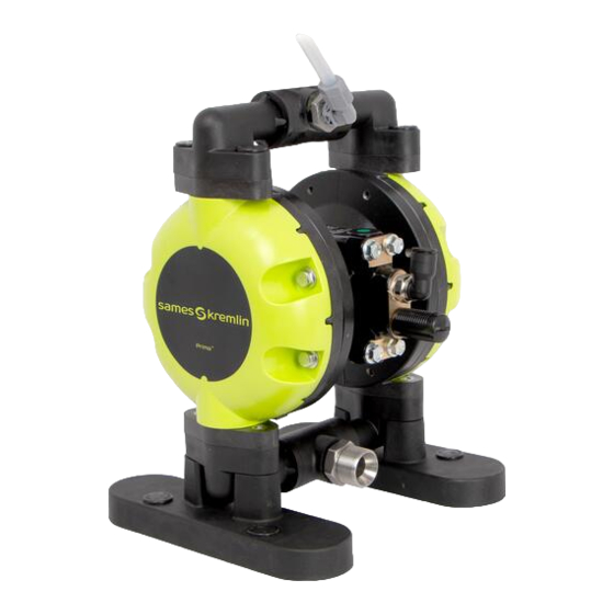
- Page 1 PRIMA 01D100 User Manual 582195110 2022-04-29 Index A Translation from the original instructions SAMES KREMLIN SAS 13 Chemin de Malacher 38240 Meylan www.sames-kremlin.com 33 (0)4 76 41 60 60...
- Page 2 Any communication or reproduction of this document, in any form whatsoever, and any exploitation or communication of its contents is prohibited, except with the express written consent of SAMES KREMLIN. The descriptions and features contained in this document are subject to change without notice.
-
Page 3: Table Of Contents
Contents CONTENTS ................................ 3 SAFETY INSTRUCTIONS ..........................9 ............................9 ERSONAL SAFETY ........................12 NTEGRITY OF THE MATERIAL DECLARATIONS ............................16 PRESENTATION OF THE MATERIAL ......................17 ........................... 17 OMPLETE SYSTEM 3.1.1 Visual generic presentation ......................17 ..................20 ESCRIPTION OF THE MAIN ELEMENTS OF THE SYSTEM IDENTIFICATION OF THE EQUIPMENT .................... - Page 4 Contents MAINTENANCE ............................53 ....................... 53 REVENTIVE AINTENANCE ................53 EQUIRED QUALIFICATION LEVELS INTERVENTION DESCRIBED ....................53 RECAUTIONS TO ENSURE MATERIAL INTEGRITY ....................55 AINTENANCE AND MONITORING PERIODS ............................... 55 LEANING ..................... 56 ISASSEMBLY EASSEMBLY OPERATIONS 9.6.1 Disassembly of the grounding cable (29) ..................58 9.6.2 Disassembly / Re-assembly of the pump ..................
- Page 5 Evolution table of the document Recording revisions Editor Object Revision Date Modified by C. HUSSON Pump, Week 12/2022 N. PLANTARD model 01D100 Dear customer, you have just purchased your new equipment and we thank you for it. We have taken the utmost care, from design to manufacture, so that this equipment gives you complete satisfaction.
- Page 6 SAMES KREMLIN is limited to the replacement of the Material in its entirety or to the partial replacement of the defective component. SAMES KREMLIN will only bear the cost of the parts necessary to replace the defective material. No guarantee will be granted by SAMES KREMLIN:...
- Page 7 Contents Meaning of the pictograms Danger, general signal Danger: high pressure Explosive materials Danger: Electricity (user) Harmful or irritating Danger of pinching, Toxic substances Corrosive materials materials crushing Risk of product Danger: hot parts or Danger of automatic Danger: flammability emanation surfaces start, moving parts...
- Page 8 Contents Personnel qualifications Tasks on the pump must only be performed in accordance with existing rules and statutory regulations, by personnel who have been instructed and are qualified in this regard, in compliance with due diligence obligations. The following requirements must be fulfilled: ...
-
Page 9: Safety Instructions
Misuse or operation can cause serious injury. Do not modify or transform the equipment. Parts and accessories must only be supplied or approved by SAMES KREMLIN. The equipment must be checked periodically. Defective or worn parts must be replaced. - Page 10 Safety instructions Security devices Attention Security devices are set up for safe use of the equipment. The manufacturer cannot be held responsible for any bodily injury as well as failures and / or damage to the equipment resulting from the destruction, hiding or total or partial removal of the safety devices.
- Page 11 Safety instructions Clean the surface of the pump housing regularly and remove the layers of dust or paint. The medium to be conveyed can corrode or destroy the pump or cause it to leak. This may lead to the formation of an explosive mixture. The conveying of explosive media and the employment in an explosion-hazardous area is only permitted according to regulations by Directive 2014/34/EU marked on the rating plate of the pump:...
-
Page 12: Integrity Of The Material
Check that the pressure relief and drain air valves are working properly. Use only genuine SAMES KREMLIN accessories and spare parts designed to withstand the operating pressure of the pump. Pump feeding phase / Pump paint phase and pressure gun / Flushing the pump / Pump defusing/ ... - Page 13 Safety instructions Hoses Recommendations for hoses. Keep hoses away from traffic areas, moving parts and hot areas. Never subject hoses to temperatures above 60 ° C / 140° F or below 0 ° C / 32° F. Do not use hoses to pull or move equipment. ...
- Page 14 It will determine the risks of immediate reactions or reactions due to repeated exposures to personnel. SAMES KREMLIN declines any responsibility, in case of: Physical or mental injury, Direct or indirect material damage due to the use of chemical substances.
- Page 15 Safety instructions Environment The equipment is installed on a horizontal, stable and flat floor (e.g. concrete slab). Non-movable equipment must be fixed to the ground by suitable mounting devices (spit, screws, bolts, etc.) to ensure its stability during use. To avoid risks due to static electricity, the equipment and its components must be grounded.
-
Page 16: Declarations
Declarations Material markings Each appliance is fitted with a nameplate bearing the name of the manufacturer, appliance reference number, important information for the use of the appliance (pressure, power, etc.) and sometimes the pictogram shown opposite. The equipment is designed and manufactured with high quality materials and components that can be recycled and reused. -
Page 17: Presentation Of The Material
Presentation of the material 3 Presentation of the material 3.1 Complete system 3.1.1 Visual generic presentation Description Description Pump Dissipative fluid hose FLUID AIR regulator Gauge GUN SPRAYING AIR regulator Gauge PUMP AIR regulator Gauge Air inlet valve Ground cable Suction rod Spraying gun* Dissipative air hose*... - Page 18 Easy flushing. This pump offers a wide range of applications for the industry. Combined with SAMES KREMLIN spray guns and Airspray hoses, it will allow you to apply your coatings with consistency and precision for an impeccable finish quality. It is compatible with most products thanks to the PTFE or PU diaphragms.
- Page 19 Presentation of the material Non-intended use or foreseeable misuse A use other than the use described in the paragraph, "Intended use" and in this operating manual, and any use that extends beyond the specified intended use, shall apply as non-intended use. The manufacturer shall not be liable damage resulting from non-intended use.
-
Page 20: Description Of The Main Elements Of The System
Presentation of the material 3.2 Description of the main elements of the system Expected use Easy design : easy operation and maintenance. Compact diaphragms technology: constant and extremely low pulsation delivery for superior finish. Distributor with spring to leave the piston in up stroke to prevent from the pump stopping. -
Page 21: Identification Of The Equipment
Identification of the equipment 4 Identification of the equipment 4.1 Description of the label marking Principles Paint pumps are designed to be installed in a paint booth. This equipment complies with the following provisions: ATEX Directive (2014/34 / EU : II 2 G - group II, category 2, gas). - Page 22 Great Britain (England, Wales, Scotland) on January 2021 P air (BAR/PSI) Maximum air pressure PMS (BAR/PSI) Maximum working pressure Number given by SAMES KREMLIN. SER.No The first 2 digits indicate the manufacture year. TYPE Model of the pump * Temperature class...
-
Page 23: Standards And Guidelines Applied
Identification of the equipment 4.2 Standards and guidelines applied The standards applied are as follows: EN ISO 80079-36 Juin 2016 / EN ISO 80079-36 June 2016: non-electrical equipment for use in potentially explosive atmospheres - Methodology and requirements - Explosive atmospheres. - Part 36: non-electrical equipment for use in potentially explosive atmospheres - Methodology and requirements. -
Page 24: Equipment Plans
Identification of the equipment 4.3 Equipment plans 4.3.1 Bare pump, model 01D100 582195110-Complete_Pump-PRIMA-01D100-EN-indA... -
Page 25: Pump, Model 01D100 + Air Equipment With 1 Regulator
Identification of the equipment 4.3.2 Pump, model 01D100 + air equipment with 1 regulator View with wall-mounting support cm / " 230 cm / 90.5" 161 cm / 63.4" 11 cm / 4.3" 10 cm / 3.9" 64 cm / 25.2" 85 cm / 33.4"... -
Page 26: Pump, Model 01D100 + Air Equipment With 2 Regulators (Pump Motor + Atomizing Air)
Identification of the equipment 4.3.3 Pump, model 01D100 + air equipment with 2 regulators (pump motor + atomizing air) cm / " 373 cm / 146.8" 188 cm / 74" Ø 14 Ø 7 F G 3/8" 22 cm / 8.6" 64 cm / 25.2"... -
Page 27: Pump, Model 01D100 + Air Equipment With 2 Regulators (Atomizing Air + Material Regulation Control)
Identification of the equipment 4.3.4 Pump, model 01D100 + air equipment with 2 regulators (atomizing air + material regulation control) cm / " 355 cm / 139.7" 188 cm / 74" Ø 14 Ø 7 F G 3/8" Ø 7 22 cm / 8.6"... -
Page 28: Pump, Model 01D100 + Air Equipment With 3 Regulators (Pump Motor + Atomizing Air + Material Regulation Control)
Identification of the equipment 4.3.5 Pump, model 01D100 + air equipment with 3 regulators (pump motor + atomizing air + material regulation control) cm / " 373 cm / 146.8" 189 cm / 74.4" Ø 14 Ø 7 F G 3/8" Ø... -
Page 29: Pump, Model 01D100 + Air Equipment + Wall-Mounted Support
Identification of the equipment 4.3.6 Pump, model 01D100 + air equipment + wall-mounted support cm / " Fixing Plate Ø 6.5 64 cm / 25.2" Ø 9 64 cm / 25.2" Filter / REGPro 40 cm / 15.7" 2 x M6 7 x M6 PRIMA 236 cm / 92.9"... - Page 30 Identification of the equipment cm / " 428.4 cm / 168.5" 451.6 cm / 177.5" 378.6 cm / 148.8" 486.2 cm / 191.3" 463.5 cm / 182.3" 307.1 cm / 120.9" 501.9 cm / 197.2" 433 cm / 170.5" 393.6 cm / 154.7" 582195110-Complete_Pump-PRIMA-01D100-EN-indA...
-
Page 31: Tripod Pump, Model 01D100
Identification of the equipment 4.3.7 Tripod pump, model 01D100 cm / " 397.1 cm / 156.3" 702.2 cm / 276.4" 1079.8 cm / 424.8" 582195110-Complete_Pump-PRIMA-01D100-EN-indA... -
Page 32: Cart Pump, Model 01D100
Identification of the equipment 4.3.8 Cart pump, model 01D100 cm / " 447.2 cm / 176" 578.3 cm / 227.5" 1085.1 cm / 427.2" 582195110-Complete_Pump-PRIMA-01D100-EN-indA... -
Page 33: Composition
Identification of the equipment 4.4 Composition The PRIMA 01D100 pump is available in PTFE or PU version: PRIMA 01D100 PTFE diaphragms pump, PRIMA 01D100 PU diaphragms pump (for abrasive materials). Please refer to the spare parts section for more information. 4.5 Options We offer you a wide choice of accessories... -
Page 34: Technical Features And Operating Principle
Technical features and operating principle 5 Technical features and operating principle 5.1 Technical features Capacity 50cc Delivery per cycle 100cc Fluid pressure ratio 1 : 1 Fluid inlet connection F 1/2" BSPP Fluid outlet connection F 3/8" BSPP Air inlet connection (with elbow) Hose 8x10 Air inlet connection (without elbow) G 3/8"... - Page 35 Technical features and operating principle Wetted parts 01D100 Standard Enamalled version version Fluid diaphragms PTFE Air diaphragms Rubber canvas Flanges PP 30% carbon fiber filled Collectors and ball cage PP 30% fiberglass Seals (fluid part) Seals (air part) Nitrile Seats and balls STEEL Pump central body (air part) Aluminium...
-
Page 36: Operating Principle
Technical features and operating principle 5.2 Operating principle NOTA The operating principle below mentions the materials you will need to purchase (air equipment, suction rod, regulator, etc.) to operate the PRIMA 01D100 pump correctly. Please refer to the Accessories section for more information. Operating principle with PRIMA 01D100 pump fitted with a 3 regulators air equipment... - Page 37 Technical features and operating principle This pumping technology is a pneumatic pump used for delivering fluid at low pressure. It can also be used for paint circulating system or as transfer pump. The pump consists of : A central air motor (1), ...
-
Page 38: Installation
Installation 6 Installation WARNING Personnel are in danger due to improper installation. Connections are to be used whose material is compatible with the pumped fluid and with the material of the pump. The pump has no separate pneumatic shut-off valve. If the pump cannot be switched off by simply, safely disconnecting or switching off the compressed air supply, an additional, easily accessible shut-off valve must be installed in front of the... -
Page 39: Transport
Comply with the rules in force in your locality. Examine the pump for any transport damage. Transport damage must be immediately communicated to the transport company and SAMES KREMLIN in writing. Protect the pump from further damage. Use the packing slip to verify the completeness of the delivery. -
Page 40: Storage
Installation 6.4 Storage Place the equipment away from moisture after closing the various air inlets and various openings (plugs). Storage conditions have a detrimental effect on the service life of the diaphragms. Thoroughly cleaning is mandatory before put away the pump for storage. -
Page 41: Start Up
Start up 7 Start up WARNING Please refer to § 1 Safety Instructions for more information. 7.1 Commissioning instructions During operation, make sure that the pump is always completely filled with liquid. Make sure that the outlet point of the fluid to be conveyed is not clogged or closed. -
Page 42: User Settings
Start up 7.2 User settings NOTA The start-up below mentions the materials you will need to purchase (air equipment, suction rod, regulator, etc.) to operate correctly the PRIMA 01D100 pump. Please refer to the Accessories section for more information. Visual with PRIMA 01D100 pump fitted with a 3 regulators air equipment Description... - Page 43 Start up Before starting up, connect the pump to the ground. Then : Turn counterclockwise the air regulators (B, C & D). Interconnect the equipment with the air pressure network (clean dry air, maximum air pressure = 6 bar / 87 psi). Install a water drop, model 3/8 if necessary.
-
Page 44: Diagnostic Help / Troubleshooting Guide
Diagnostic help / Troubleshooting guide 8 Diagnostic help / Troubleshooting guide Troubleshooting Before any intervention on the pump, hoses or outlet valve, it is imperative to carry out a general procedure of decompression and drain. In order to avoid the risk of personal injury, product injections, injuries caused by moving parts or arcing, it is essential to follow the following procedure before any intervention during system shutdown, assembly, cleaning or changing the nozzle. -
Page 45: Possible Symptoms Of Faults / Causes Of Faults / Remedies To Apply - Fast Operation
Diagnostic help / Troubleshooting guide 8.1 Possible symptoms of faults / Causes of faults / Remedies to apply - fast operation WARNING Before any intervention, it is imperative to follow the decompression procedure and the safety instructions. Shut off the air inlet then depressurize the fluid network by opening the gun. - Page 46 Diagnostic help / Troubleshooting guide Defaults Possible causes Remedies The pump does not work or Hose cross section too small Change the hose using an hose with works slowly a larger cross section. Defective air distributor Disassemble and inspect the air distributor and pilot spool.
- Page 47 Diagnostic help / Troubleshooting guide Defaults Possible causes Remedies Priming trouble Bubbles on the suction side Check the suction and tightness conditions between the pump and the suction rod (or cup). Bring the pump closer to the product. Check the condition of the seals on the collectors.
- Page 48 Diagnostic help / Troubleshooting guide Defaults Possible causes Remedies Air leakage on the suction Inspect all tightness seals and fittings side or presence of air in the - suction side. Replace them if product necessary. Check the condition of the air diaphragms.
- Page 49 Diagnostic help / Troubleshooting guide Defaults Possible causes Remedies Pump running slowly, Presence of ice Remove the muffler cover. Clean irregularly or stalling; poor and/or remove ice. Reassemble the flow muffler. Install an air dryer. Collectors clogged Clean the collectors to allow good circulation of the product.
- Page 50 Diagnostic help / Troubleshooting guide Defaults Possible causes Remedies Presence of pumped fluid in Disassemble the pump chambers. the muffler of the air exhaust Check for damage to the fluid line and/or air diaphragms. Replace them if necessary. Check the tightness of the diaphragm washers (tightening torque: 7.5 N.m.
- Page 51 Diagnostic help / Troubleshooting guide Defaults Possible causes Remedies Diaphragm damaged, Bubbles on the suction side Check the suction and tightness defective or leaking conditions between the pump and the suction rod (or cup). Bring the pump closer to the product. Check the condition of the seals on the collectors.
- Page 52 Diagnostic help / Troubleshooting guide Defaults Possible causes Remedies The pump operates but Valves clogged up Clean the pump with the does not convey fluid or appropriate cleaning solvent. stops Clean or change the valves. Valves worn or/and Check and change the parts. incorrectly mounted Exhaust hose clogged Clean or change the exhaust hose.
-
Page 53: Maintenance
Maintenance 9 Maintenance 9.1 Preventive Maintenance Plan WARNING Please refer to the preventive maintenance plan in § 11 Appendices more information. 9.2 Required qualification levels - intervention described As the pump is easy to disassemble, this type of intervention can be carried out by an authorized technician of average qualification, on site, with portable tools (wrench, screwdriver,...) defined by the maintenance instructions and the disassembly/reassembly procedures. - Page 54 Maintenance Make sure that the suction strainer is clean and in good condition. Regularly clean it and change it if necessary. Flush the pump as often as necessary, specially when spraying pigment-filled material. Ensure that the material hoses and other components are able to withstand the fluid pressure generated by this pump.
-
Page 55: Maintenance And Monitoring Periods
Maintenance 9.4 Maintenance and monitoring periods It is recommended to schedule a routine maintenance after a set number of hours of operation. This is defined by the user's maintenance department and is based on the product, the work rate and the usual pressure. This maintenance consists of replacing parts with cuts or wear and cleaning organs with compatible products without using abrasive materials that could damage them. -
Page 56: Disassembly / Reassembly Operations
Maintenance 9.6 Disassembly / Reassembly operations WARNING Before any intervention, it is imperative to follow the pressure relief procedure and the safety instructions. Preliminary operations If the pump is fitted with an air assembly Turn counterclockwise the spraying air regulator or disconnect spray gun air inlet. - Page 57 Maintenance Please refer to the corresponding disassembly/reassembly sections for more information : § 9.6.1: Grounding cable, § 9.6.2: Disassembly complete pump, Step 3 Disassembly of the exhaust valves, • Step 9: Disassembly of the suction valves, • Step 11: Disassembly of the diaphragms and of the pilot-spool, •...
-
Page 58: Disassembly Of The Grounding Cable (29)
Maintenance 9.6.1 Disassembly of the grounding cable (29) Time required 1 minute 50 Hold the grounding terminal with a 10 mm wrench and unscrew the lock nut (A) with the other key. Manually remove the washer (B), the lug (C) with its grounding wire and the washer (D). - Page 59 Maintenance Disassembly of the pump Step 1 Take off the plugs (1) by levering with a flat screwdriver, then unscrew the 4 screws (2) by means of a 10 mm socket wrench. Step 2 Separate the upper part of the pump that consists of the elbows (3) and couplings (4 and 5) assembly from the flanges (13).
- Page 60 Maintenance Disassembly of the exhaust valves 2 minutes - Time required Step 3 To remove the exhaust valves (9), use a 24 mm flat wrench. Remove the ball cage (9.2), the ball (9.3) and the seat (9.5) or remove the seat (9.5), the ball (9.3) and the ball cage (9.2) by means of a 7mm socket.
- Page 61 Maintenance Step 4 Unscrew the 4 screws (11) by means of a 10 mm socket wrench. Carry out the same procedure on the other side of the pump by unscrewing the 4 other screws (11). Step 5 Remove the covers (12). 582195110-Complete_Pump-PRIMA-01D100-EN-indA...
- Page 62 Maintenance Step 6 Unscrew the 4 screws (2) by means of a 10 mm socket wrench. Carry out the same procedure on the other side of the pump by unscrewing the 4 other screws (2). Step 7 Unscrew the 4 screws (8) located under the feet (7) by means of a 10 mm socket wrench.
- Page 63 Maintenance Step 8 Remove the 2 feet (7) from the flanges (13) as well as the lower part fo the pump that consists of the elbows (3) and coupling (4) assembly. To replace the seals in the elbows (3) and couplings (4) assembly, see steps and 29.
- Page 64 Maintenance Disassembly of the suction valves 2 minutes - Time required Step 9 To remove the suction valves (10), use a 24 mm flat wrench. Remove the ball cage (10.2), the ball (10.3) and the seat (10.5) or remove the seat (10.5), the ball (10.3) and the ball cage (10.2) by means of a 7mm socket.
- Page 65 Maintenance Disassembly of the diaphragms and of the pilot-spool 5 minutes - Time required Step 11 Unscrew the screw-washer fluid section (14) assembly by means of a 10 mm socket wrench. Counterlock on the other side using another 10 mm socket wrench. ...
- Page 66 Maintenance Step 13 Take off the 2 flat washers (21) and the 2 seals (22). Check that the seals are in place and in good condition. Change them if necessary. Step 14 Take off the pilot-spool (23) with the seals (24) by pushing them. Check that the seals are in place and in good condition.
- Page 67 Maintenance Disassembly of the distributor 6 minutes - Time required Step 15 Unscrew the 4 screws (8) by means of a 10 mm socket wrench to separate the distributor from the motor body. Step 16 Remove the plugs (30) using a flat screwdriver in the groove for leverage.
- Page 68 Maintenance Step 17 Take off the air valve spool (32) from the distributor body (37). Take off the seals (33 and 34) with a non-metal tools to avoid damaging the seals. Remove manually the muffler (38). Unscrew the fitting (39) by means of a 17 mm flat wrench. ...
- Page 69 Maintenance Reassembly of the distributor 6 minutes – Time required Step 18 Kluber petamo HY 133N Screw the fitting (39) by means of a 17 mm flat wrench. Install manually the muffler (38). Grease the inside of the distributor body (37). Caution: Do not apply too much grease to avoid clogging the holes.
- Page 70 Maintenance Step 19 Kluber petamo HY 133N Reinstall the seals (31) on the plugs (30) by greasing the entire seal contours evenly with grease. Reinstall the upper plug (30) with its seal (31) on the pump. A click is heard to indicate that it is in place.
- Page 71 Maintenance Step 20 Loctite Apply glue to the threads of the 4 screws (8) and screw them by means of a 10 mm torque wrench to reinstall the distributor on the motor body. Screwing torque : 7.5 N.m / 5.5 ft /lbs. Caution: If the screws (8) do not slide into their housings, there will be play between the parts.
- Page 72 Maintenance Step 22 Kluber petamo HY 133N Reinstall the 2 seals (22) and the 2 flat washers (21) greasing the entire seal contours evenly with grease. Caution: Observe the mounting direction of the spacer washers. A notch allows you to mount the washers in the right direction.
- Page 73 Maintenance Step 24 Kluber petamo HY 133N Reinstall the 2 seals (19) greasing the entire seal contours evenly with grease. Reinstall the coupling axis (27) by pushing it. Step 25 Kluber petamo HY 133N Reinstall the seals (18) greasing the entire seal contours evenly with grease, the washers (17), the new air diaphragms (16) and the new fluid diaphragms (15a / 15b).
- Page 74 Maintenance Step 26 Loctite Apply glue to the threads of the screw-washer fluid section assembly (14).and tighten the diaphragms with a 10 mm torque wrench, counter-clamping on the other side with a 10 mm pipe wrench. Screwing torque : 7.5 N.m / 5.5 ft /lbs. ...
- Page 75 Maintenance Caution: The screws (2) mounted in step 25 to help you when mounting the diaphragms must be removed first. Apply glue to the threads of the screws (2) and reinstall the 2 flanges (13) by screwing crosswise the screws (2) by means of a 10 mm torque wrench.
- Page 76 Maintenance Reassembly of the collector seals – Lower part 2 minutes - Time required Step 29 Kluber petamo HY 133N Reinstall the 2 seals (6) by greasing the entire seal contours evenly with grease. Reinstall the elbows (3) on the coupling (4). On reassembly, depending on the customer's requirements and its siting constraints, the coupling (4) can be turned thanks to the 4 notches provided for this purpose.
- Page 77 Maintenance Recommendations for suction and exhaust valves Warning : Comply with the installation direction of the valves. Risk of damaging the pump. There are two versions of valves : the suction valves and the exhaust valves. The suction valves cannot be installed in place of exhaust valves (different parts).
- Page 78 Maintenance Caution: Do not apply grease on the balls (9.3 and 10.3) and the seats (9.5 and 10.5) Risk of sticking. Caution: Make sure that the valves are installed in the correct direction. If the valves are installed in the wrong direction or if you have installed the exhaust valves instead of the suction valves or the exhaust valves onstead of the suction valves, there will be a gap between the parts.
- Page 79 Maintenance Reassembly of the suction valves 2 minutes - Time required Step 30 Kluber petamo HY 133N Change the seals (10.1) and (10.4) if necessary. Reinstall them by greasing the entire seal contours evenly with grease. Reinstall the parts (10.2), (10.3) and (10.5). Step 31 Loctite ...
- Page 80 Maintenance Step 32 Reinstall the covers (12). Step 33 Loctite Apply glue to the threads of the 4 screws (11) and screw them by means of a 10 mm torque wrench. Screwing torque : 7.5 N.m / 5.5 ft /lbs. ...
- Page 81 Maintenance Reassembly of the exhaust valves 2 minutes - Time required Step 34 Caution: Please refer section Recommendations for suction and exhaust valves. Kluber petamo HY 133N Change the seals (9.1) and (9.4) if necessary. Reinstall them by greasing the entire seal contours evenly with grease.
- Page 82 Maintenance Disassembly of the collector seals – Upper part 2 minutes - Time required Step 35 Separate the elbows (3) from the coupling (4). Remove the 2 seals (6). Check seals. Change them if necessary. Reassembly of the collector seals – Upper part 2 minutes - Time required Step 36...
- Page 83 Maintenance Step 37 Reinstall the upper part of the pump that consists of the elbow (3) and coupling (4 and 5) assembly on the flanges (13). Step 38 Loctite Apply glue to the threads of the screws (2) and reinstall them means torque wrench.
-
Page 84: Spare Parts
Spare parts 10 Spare parts Use only genuine SAMES KREMLIN accessories and spare parts designed to withstand the operating pressures of the pump. Please refer to the relevant sections for more information : § 10.1 : Exploded overview, § 10.2 : Diaphragm assembly and pilot chamber, ... -
Page 85: Exploded Overview
Spare parts 10.1 Exploded overview 582195110-Complete_Pump-PRIMA-01D100-EN-indA... -
Page 86: Diaphragms Assembly And Pilot Chamber
Spare parts 10.2 Diaphragms assembly and pilot chamber 582195110-Complete_Pump-PRIMA-01D100-EN-indA... -
Page 87: Upper Part And Exhaust Valves
Spare parts 10.3 Upper part and exhaust valves 582195110-Complete_Pump-PRIMA-01D100-EN-indA... -
Page 88: Lower Part And Suction Valves
Spare parts 10.4 Lower part and suction valves 582195110-Complete_Pump-PRIMA-01D100-EN-indA... -
Page 89: Distributor
Spare parts 10.5 Distributor 582195110-Complete_Pump-PRIMA-01D100-EN-indA... -
Page 90: Wear Part Numbers
Spare parts 10.6 Wear part numbers # Part number Description 144 936 500 PRIMA 01D100 PTFE diaphragms pump 144 936 550 PRIMA 01D100 PU diaphragms pump # Part number Description Level** 906 380 905 Plug 300F 931 231 277 Screw HM 6x20 CL. 8.8 black oxided (pack of 12) 144 936 512 Elbow... - Page 91 Spare parts # Part number Description Level** 144 936 093 Screw HM 6x25 CL. 8.8 zinc (pack of 8) 144 936 036 Cover 144 936 014 Fluid flange 144 936 040 Screw washer fluid section *15a PTFE fluid diaphragm included in pack *15b PU fluid diaphragm included in pack...
-
Page 92: Part Numbers For Spare Parts Or Repair Kits
Spare parts # Part number Description Level** 144 936 540 Complete air distributor 144 936 521 Plug for air distributor (pack of 2) 909 420 300 NBR black seal 70 SH Ø int 18.5 included in packs - Ø tore 1 144 936 241 Air valve spool ... - Page 93 Spare parts Packs of seals # Part numbers Description 31, 33, 144 936 022 Pack of seals for air distributor that consists of : - 2 NBR black seals 70 SH Ø int 18.5 - Ø tore 1, 34, 35 - 1 NBR black seal 80 SH Ø...
- Page 94 Spare parts Accessories Plates and their spare parts # Part number Description 151 751 206 Air plate 3 regulators (pump motor + atomizing air + material regulation control) 151 751 212 Air plate 2 regulators (pump motor + atomizing air) 151 751 213 Air plate 2 regulators (atomizing air + material regulation...
- Page 95 Spare parts Other accessories # Part number Description 144 907 070 Wall mounting bracket for diaphragm pump 149 596 150 Suction rod Ø 23 for drum 60L – F 26x 125 149 596 160 Suction rod Ø 25 for drum 200L –...
- Page 96 Spare parts # Part number Description 151 140 250 Gravity cup 6L with L adaptator 050 102 437 Fitting M 1/2 – M 26 X 125 stainless steel 155 581 641 LP low pressure filter - screen n°6 outlet 3/8 NPS (Refer to Doc.
- Page 97 Spare parts # Part number Description 151 757 010 Complete stainless steel circulating assembly for diaphragms pump 050 102 418 Fitting, MM 18 x 125 – 15 x 21 stainless steel 151 730 130 Tripod (Refer to Doc. 582.220.110) 151 730 140 Cart kit (tripod + wheels) (Refer to Doc.
-
Page 98: Consumable References
Spare parts 10.8 Consumable references # Part number Description 560 420 005 Box of grease (450 gr / 1lb) 560 440 005 Box of grease Kluber petamo HY 133N (1 Kg / 2.2 lbs) 554 180 010 Loctite 222 (50 ml / 1.7 oz) 554 180 015 Loctite 5772 (50 ml / 1.7 oz) 582195110-Complete_Pump-PRIMA-01D100-EN-indA... -
Page 99: Appendices
Appendices 11 Appendices 11.1 Appendix A Declarations 582195110-Complete_Pump-PRIMA-01D100-EN-indA... -
Page 100: Appendixb Preventive Maintenance Plan
This partly completed machinery must not be put into service until the final machinery in which it is to be incorporated has been declared in conformity with Directive 2006/42/CE on Machinery. SAMES KREMLIN is allowed to compil the technical documentation. SAMES KREMLIN undertakes to transmit, in response to a reasoned request by the national authorities, relevant information on the partly completed machinery in the most appropriate form. - Page 101 机构 Cette quasi-machine ne doit pas être mise en service avant que la machine finale dans laquelle elle doit être incorporée n'ait été déclarée conforme à la directive 2006/42/CE relative aux machines. SAMES KREMLIN est autorisée à établir la documentation technique. SAMES KREMLIN s'engage à transmettre, en réponse à une demande motivée des autorités nationales, les informations pertinentes sur la quasi-machine sous la forme la plus appropriée.
- Page 102 This partly completed machinery must not be put into service until the final machinery in which it is to be incorporated has been declared in conformity with Supply of Machinery (Safety) Regulations 2008. SAMES KREMLIN is allowed to compil the technical documentation. SAMES KREMLIN undertakes to transmit, in response to a reasoned request by the national authorities, relevant information on the partly completed machinery in the most appropriate form.
- Page 103 će se ugraditi u skladu s Pravilnikom o opskrbi strojevima (sigurnost) iz 2008. SAMES KREMLIN je ovlašten za izradu tehničke dokumentacije. SAMES KREMLIN...
- Page 104 Appendices 11.2 Appendix B Preventive Maintenance Plan 582195110-Complete_Pump-PRIMA-01D100-EN-indA...
- Page 105 Les périodicités mentionnées sont des moyennes basées sur l’expérience de Sames Kremlin. A charge des utilisateurs de les adapter aux conditions de leur installation notamment en fonction de la nature des produits utilisés, des vitesses de travail, etc. Sames Kremlin se réserve...
- Page 106 Pompe PRIMA 01D100 PMP582174110 PLAN DE MAINTENANCE PREVENTIVE / PREVENTIVE MAINTENANCE PLAN Pour 1 ensemble - For 1 assembly SAMES KREMLIN Acteurs Métiers Niveau 13, chemin de Malacher - Inovallée Temps prévu Notice Operators - skill Level Périodicité 38243 MEYLAN - France Sous ensemble Désignation de l'élément...
- Page 107 Boite de graisse 450g 560 420 005 Box of grease 450g Boite de graisse kluber petamo HY 133N 450kg 560 460 005 Box of grease kluber petamo HY 133N 1kg PMP582174110-PRIMA 01D100.xlsx, Spare Parts Page 3/4 Updated on 01.12.2021 C.Baillet...
- Page 108 Joint Bleu 70 SH Ø int 15,6 - Ø tore 1,78 109 420 283 O-ring Chambre de Joint U pilotage 109 060 301 O-ring Pilot chamber Joint Noir 90 SH 10,5 x 2,70 (notice 582174110) 909 130 411 O-ring PMP582174110-PRIMA 01D100.xlsx, Spare Parts Page 4/4 Updated on 01.12.2021 C.Baillet...
Need help?
Do you have a question about the PRIMA 01D100 and is the answer not in the manual?
Questions and answers