Pilz PSSuniversal Installation Manual
Programmable
Hide thumbs
Also See for PSSuniversal:
- Technical catalogue (167 pages) ,
- System description (89 pages)
Table of Contents
Advertisement
Quick Links
Advertisement
Table of Contents

Subscribe to Our Youtube Channel
Related Manuals for Pilz PSSuniversal


Summary of Contents for Pilz PSSuniversal
- Page 1 PSSuniversal Programmable control systems PSS Installation Manual-21262-EN-07...
- Page 2 Preface This document is a translation of the original document. All rights to this documentation are reserved by Pilz GmbH & Co. KG. Copies may be made for internal purposes. Suggestions and comments for improving this documentation will be gratefully received.
-
Page 3: Table Of Contents
Mechanical coding of the electronic modules 4.5.1 Removing the mechanical coding from an electronic module 4.5.2 Removing the mechanical coding from a base module Steps 4.6.1 Procedure for installing the PSSuniversal 4.6.2 Procedure for removing the PSSuniversal Section 5 Installing the modules Head modules 5.1.1 Installing the head module 5.1.2... - Page 4 Connecting the PSSu system Supply voltages Power supplies Earthing Separation of supply Wiring the base modules 6.5.1 Cable requirements 6.5.2 Connecting FS inputs and outputs Wiring the compact modules 6.6.1 Cable requirements Wiring test and function test Installation Manual PSSuniversal 21262-EN-07...
-
Page 5: Installation Manual Pssuniversal
System Description PSS 4000 PSSuniversal System Description The modules for the PSSuniversal are described in detail in the respective operating manu- als. This documentation is intended for instruction and should be retained for future reference. This documentation is valid for the PSSuniversal. - Page 6 Introduction INFORMATION This gives advice on applications and provides information on special fea- tures. Installation Manual PSSuniversal 21262-EN-07...
-
Page 7: Safety
Ensure VDE and local regulations are met, especially those relating to safety. The rel- evant safety regulations for the respective application must also be met. The PSSuniversal is exclusively designed for use in an industrial environment. It is not suitable for use in a domestic environment, as this can lead to interference. -
Page 8: Installation
2.3.2 Installation Please note: Install the PSSuniversal in a protected environment, e.g. in a control cabinet or a pro- tected interior compartment. Comply with the protection class required for the installation environment. Refer to the technical details of the relevant modules during installation. -
Page 9: Esd
PSSu system [ 16]. 2.3.3 NOTICE Damage due to electrostatic discharge! Electrostatic discharge can damage components. Ensure against discharge before touching the product, e.g. by touching an earthed, conductive sur- face or by wearing an earthed armband. Installation Manual PSSuniversal 21262-EN-07... -
Page 10: Electromagnetic Compatibility (Emc)
A cable can emit a signal as a radio wave. This wave is then picked up by another cable. – Typical sources of interference are transmitters such as radios, sparks from spark plugs, welding equipment, etc. Installation Manual PSSuniversal 21262-EN-07... -
Page 11: Making The Installation Emc-Compliant
Group 2: Data and supply lines for DC voltages from 60 V to 400 V and AC voltages from 25 V to 400 V. Group 3: Supply lines above 400 V Cabling inside buildings The cable groups listed above should be laid separately. Installation Manual PSSuniversal 21262-EN-07... -
Page 12: Connecting The Fieldbuses
Use copper or galvanised steel equipotential bonding cable. Connect equipotential bonding cables to the earth bar over as wide a surface area as possible. As short a distance as possible should be kept between the equipotential bonding cable and signal cable. Installation Manual PSSuniversal 21262-EN-07... -
Page 13: Screening
At the point where the cable enters the cabinet, connect the shield to the earth bar, without making a break in the cable. Use metal cable clamps which cover the shield over a wide surface area. Take the screen as far as the PSSuniversal, but do not lay it on top of the PSSuniversal. -
Page 14: Lighting In The Control Cabinet
Remove insulation or use special contact fix- ings; protect the connection from corrosion; connect the cabinet doors to the body of the cabinet using earthing straps Installation Manual PSSuniversal 21262-EN-07... - Page 15 PSSu must be wired with sup- pression elements. 24 VDC power supply? As regards safe separation, power supplies must conform to EN 60950-1, 02.2011, section 2.3, EN 61558-1, 11/2006 or EN 50178, 10/97 Installation Manual PSSuniversal 21262-EN-07...
-
Page 16: Installing The Pssu System
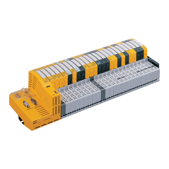
Installing the PSSu system Installing the PSSu system Modular structure The PSSuniversal is a modular, programmable system for controlling plant and machinery. The PSSuniversal Configurator/PSS 4000 system software is available for configuration. The PSSuniversal Assistant software/Tool Suite PAS4000 provides support when selecting components. -
Page 17: Module Layout
Module layout The first module on a PSSuniversal system is always a head module. If the head module does not have an integrated power supply, a supply voltage module is connected to the right of the head module. The supply voltage module is used –... -
Page 18: Connection Levels
– It is not possible to mix base modules with screw terminals and base modules with spring-loaded terminals in one PSSuniversal system. – The maximum number of input/output modules is determined through the defined system limits. -
Page 19: Colour Marking On The Connection Levels
10-pin connector strip. The function of the connections depends on the compact module. Terminal row 1 Connection of the inputs and outputs, periphery supply (24 V and 0 V). Installation Manual PSSuniversal 21262-EN-07... - Page 20 Input/output modules can be installed in any order. However, for the connection diagram to be consistent it makes sense to arrange input/output modules of the same type into groups. Single-row connector Three-row connector Terminal rows Terminal rows 24 V 24 V Inputs or Inputs or outputs outputs Installation Manual PSSuniversal 21262-EN-07...
-
Page 21: Installation Environment
The T-type PSSu modules are suitable for use where there are increased environmental re- quirements on temperature and humidity. Please refer to the technical details. With some T-type output modules, please also note the derating at higher temperatures. Installation Manual PSSuniversal 21262-EN-07... -
Page 22: Mounting Distances
The ambient temperature of the PSSu system in the control cabinet must not exceed the figure stated in the technical details for the modules, Air conditioning may otherwise be re- quired. 35 mm (1.378") 20 mm 20 mm (0.787") (0.787") 35 mm (1.378") Fig.: Mounting distances when installed horizontally Installation Manual PSSuniversal 21262-EN-07... -
Page 23: Mechanical Coding Of The Electronic Modules
Once a base module has been coded, it will only take electronic mod- ules with the same mechanical coding. The coding is identified by a letter and a colour. Codings with the same letters are mechan- ically identical and are distinguished through a different colour. Installation Manual PSSuniversal 21262-EN-07... - Page 24 Details of the mechanical coding of the electronic modules (type and colour) can be found in the technical details in the data sheet and operating manual. Coding element Coding element on counterpart Type Electronic module Base module Installation Manual PSSuniversal 21262-EN-07...
-
Page 25: Removing The Mechanical Coding From An Electronic Module
Prerequisite – Base module must be removed from the rail. Procedure: – Use a screwdriver for slotted-head screws (M2). – Insert the screwdriver into the coding. – Remove the coding element laterally. Installation Manual PSSuniversal 21262-EN-07... - Page 26 Installing the PSSu system Installation Manual PSSuniversal 21262-EN-07...
-
Page 27: Steps
Installing the PSSu system Steps 4.6.1 Procedure for installing the PSSuniversal We recommend the following procedure for installing a PSSuniversal. The individual steps are described in detail on the pages that follow. WARNING! Risk of electrocution! When voltage is applied, contact with live components could result in seri- ous or even fatal injury from an electric shock. - Page 28 Pull the electronic modules from the base modules. Remove the base module wiring. Remove the end bracket on the right with the terminating resistor. Remove the end bracket on the left. Remove the compact modules. Remove the base modules. Remove the head module. Installation Manual PSSuniversal 21262-EN-07...
-
Page 29: Installing The Modules
30 mm) or have been removed from the rail. Procedure: Using a screwdriver, push the rear locking element [1] upwards until the locking hook releases the anchor. Pivot the head module and screw driver forwards [2] and remove in a downward direc- tion [3]. Installation Manual PSSuniversal 21262-EN-07... -
Page 30: Base Modules
The mechanics of the base modules are designed for 50 plug in/out cycles. Procedure: We recommend that you wire up the base modules before inserting the electronic mod- ules. Slot the groove on the base module on to the mounting rail from below [1]. Installation Manual PSSuniversal 21262-EN-07... -
Page 31: Removing Base Modules
On the mounting rail, slide the base module to the right [3] Using a screwdriver, push the rear locking element [4] upwards [5] until the locking hook releases the anchor. Pivot the base module and screw driver forwards and remove in a downward direction. Installation Manual PSSuniversal 21262-EN-07... - Page 32 Installing the modules Installation Manual PSSuniversal 21262-EN-07...
-
Page 33: Electronic Modules
The mechanics of the electronic modules are designed for 50 plug in/out cycles. 5.3.1 Inserting an electronic module Procedure: The electronic module must audibly lock into position [1]. Mark the electronic module using the labelling strips [2]. Schematic representation: Installation Manual PSSuniversal 21262-EN-07... -
Page 34: Removing An Electronic Module
The mechanics of the compact modules are designed for 50 plug in/out cycles. Procedure: Slot the groove on the compact module on to the mounting rail from below [1]. Push the compact module back as far as it will go [2]. Installation Manual PSSuniversal 21262-EN-07... -
Page 35: Remove The Compact Modules
All the wiring must be removed All the compact modules to the right of the relevant base module must have been moved to the right (min. 30 mm) or have been removed from the rail. Procedure: Pull out the locking mechanism [1] Installation Manual PSSuniversal 21262-EN-07... -
Page 36: End Bracket
Place the end bracket on the mounting rail, to the left of the head module [1]. Slide the end bracket up close to the head module [2] Tighten up the end bracket [3]. Installation Manual PSSuniversal 21262-EN-07... -
Page 37: Install A Connection Plate On The Right
Insert the screwdriver into the terminating plate [5] Tighten up the integrated end bracket [6]. If an additional metallic end bracket is required to secure the system, this additional end bracket is installed to the right of the terminating plate. Installation Manual PSSuniversal 21262-EN-07... -
Page 38: Remove The End Bracket On The Left
Remove the end bracket on the left Procedure: Use a screwdriver for slotted-head screws (M2). Loosen the fixing screw on the end bracket until the terminals' clamping force is lifted. Remove the end bracket from the mounting rail. Installation Manual PSSuniversal 21262-EN-07... -
Page 39: Remove The Connection Plate On The Right
Please note: Do not damage the elements used to connect to the adjacent base mod- ule. Loosen the fixing screw on the end bracket until the terminals' clamping force is lifted. Remove the terminating plate and integrated end bracket from the mounting rail. Installation Manual PSSuniversal 21262-EN-07... -
Page 40: Connecting The Pssu System
The module supply and periphery supply have separate connections for the respective earth potential (Ground). Functional earth A contact spring on the base modules and compact modules connects the modules' functional earth to the mounting rail. Installation Manual PSSuniversal 21262-EN-07... - Page 41 VDC may not be connected parallel to the module supply. Insulation of supplies in a PSSu installation: Relay module C-rail Switch contact 1 Failsafe fieldbus Module Periphery C-rail supply supply Standard fieldbus Relay module Safe separation C-rail Switch contact 2 Basic insulation Functional insulation Installation Manual PSSuniversal 21262-EN-07...
-
Page 42: Power Supplies
PSSu system, even when the supply groups are different. The connection of the 0 V supply to the central earth bar or earth fault monitor must be in accordance with national regulations (e.g. EN 60204-1, NFPA 79:17-7, NEC: Art- icle 250). Installation Manual PSSuniversal 21262-EN-07... - Page 43 Earth bar Module Supply Periphery Supply Periphery Supply C-Rail C-Rail Module Supply Periphery Supply If the bridge is removed, Periphery Fieldbus -Sensors earth fault monitoring -Actuators must be used in accordance with EN 60204 / VDE 0113. Installation Manual PSSuniversal 21262-EN-07...
- Page 44 Mounting rail Functional earth Module Supply Earth bar Module Supply Periphery Supply Periphery Supply C-Rail C-Rail Module Supply Periphery Supply Earth fault monitoring Periphery Fieldbus is required in accordance -Sensors with EN 60204 / VDE 0113. -Actuators Installation Manual PSSuniversal 21262-EN-07...
- Page 45 Earth bar Module Supply Periphery Supply Periphery Supply C-Rail C-Rail Module Supply Periphery Supply If the bridge is removed, Periphery Fieldbus earth fault monitoring -Sensors must be used in -Actuators accordance with EN 60204 / VDE 0113. Installation Manual PSSuniversal 21262-EN-07...
-
Page 46: Earthing
The earthing terminal is available as an accessory. The mounting rail must be properly earthed to ensure interference-free operation in accordance with EMC regulations. The supplies on the PSSuniversal module bus (module supply, periphery supply, C-rail) are not connected to the functional earth through the contact spring. -
Page 47: Separation Of Supply
PSSu BS-R 2/8 C PSSu E F PS-P PSSu BS 1/8 S No refreshing (5 V is not PSSu BS 1/8 C separated). PSSu E F BSW PSSu BS 2/8 S PSSu BS 1/8 C Installation Manual PSSuniversal 21262-EN-07... -
Page 48: Wiring The Base Modules
If necessary, label the connection level with a colour marker [3]. Base module with screw terminals: – Use a screwdriver to loosen the screw on the screw terminal [1] – Insert the stripped cable into the round fixing hole [2], as far as it will go. Installation Manual PSSuniversal 21262-EN-07... -
Page 49: Cable Requirements
The maximum cable cross section for field connection terminals is: – Digital inputs: 1.5 mm (AWG16) – Digital outputs: 2.0 mm (AWG14) – Inputs/outputs on the counter modules: 1.5 mm (AWG16) – Analogue inputs/outputs: 1.5 mm (AWG16) – Communication cables: 1.5 mm (AWG16) – Test pulse outputs: 1.5 mm (AWG16) Installation Manual PSSuniversal 21262-EN-07... -
Page 50: Connecting Fs Inputs And Outputs
Using the screwdriver, press the actuator button on the spring-loaded terminal down as far as it will go [2], keep it held down and insert the stripped cable into the plug connec- tion as far as it will go [2]. Check that the cable is firmly seated [3]. Installation Manual PSSuniversal 21262-EN-07... -
Page 51: Cable Requirements
Terminal points per connection: 1 Stripping length: 8 mm Wiring test and function test CAUTION! The PSSuniversal may be damaged by wiring errors or by modules being inserted incorrectly. For this reason, please follow the correct sequence when commissioning. Prerequisite: Mechanical structure is complete. - Page 52 Connecting the PSSu system Procedure: Apply the supply voltage for the module supply. Do not apply any other voltages! Download configuration data to the PSSuniversal. – The head module checks that the hardware registry is correct. If an electronic mod- ule or compact module is inserted incorrectly, this will be detected and will lead to an error message.
- Page 53 Front cover Support Technical support is available from Pilz round the clock. Americas Australia Scandinavia Brazil +61 3 95600621 +45 74436332 +55 11 97569-2804 Spain Canada Europe +34 938497433 +1 888-315-PILZ (315-7459) Austria Switzerland +41 62 88979-30 Mexico +43 1 7986263-0...
Need help?
Do you have a question about the PSSuniversal and is the answer not in the manual?
Questions and answers