
Related Manuals for Xylem FLYGT Pareo DCM 711


Summary of Contents for Xylem FLYGT Pareo DCM 711
- Page 1 Installation, Operation, and Maintenance Manual 90010501_3.0 DCM 711 ™ Pareo DCM 711 Control Module/Pareo...
- Page 3 About this manual This manual describes the installation, operation, and maintenance of DCM 711. Other manuals • Installation, Operation, and Maintenance manual for the pump: For information about the safe and recommended procedure of installing, operating, and maintaining the pump –...
-
Page 5: Table Of Contents
Table of Contents Table of Contents 1 Introduction and Safety......................4 1.1 Introduction........................4 1.2 Safety terminology and symbols..................4 1.3 User safety........................5 1.3.1 Power lock-out......................5 1.3.2 Qualification of personnel..................5 1.4 End-of-life product disposal................... 5 1.5 Spare parts........................6 1.6 Warranty........................ - Page 6 Table of Contents 4.3.2 Electrical installation..................... 19 4.3.3 Optional parts......................21 4.4 Pareo DCM 711 control module.................. 21 4.4.1 Installation requirements..................21 4.4.2 Mechanical installation..................21 4.4.3 Electrical Installation..................... 22 5 System Setup and Operation..................... 24 5.1 Commissioning......................24 5.2 Run the Setup Wizard....................24 5.3 Common procedures....................
- Page 7 Table of Contents 9.1.2 Dimensions......................44 9.1.3 Environmental requirements................. 45 9.1.4 Electrical data....................... 45 9.1.5 Glass fuse properties.................... 45 9.1.6 Terminals......................46 9.2 Pareo DCM 711 control module.................. 47 9.2.1 Variants.........................47 9.2.2 Dimensions......................47 9.2.3 Environmental requirements................. 47 9.2.4 Electrical data....................... 47 9.2.5 Terminals......................
-
Page 8: Introduction And Safety
This includes any modification to the equipment or use of parts not provided by Xylem. If there is a question regarding the intended use of the equipment, please contact a Xylem representative before proceeding. -
Page 9: User Safety
Risk of electrical shock or burn. A certified electrician must supervise all electrical work. Comply with all local codes and regulations. All work on the product must be carried out by certified electricians or Xylem authorized mechanics. Xylem disclaims all responsibility for work done by untrained, unauthorized personnel. -
Page 10: Spare Parts
The use of unsuitable spare parts may cause malfunctions, damage, and injuries as well as void the warranty. 1.6 Warranty For information about warranty, see the sales contract. 1.7 Support Xylem only supports products that have been tested and approved. Xylem does not support unapproved equipment. DCM 711 Installation, Operation, and Maintenance Manual... -
Page 11: Product Description
2 Product Description 2 Product Description 2.1 Product design DCM 711 is a controller for a single-pump installation. The controller is part of the Pareo system. The controller is available as a control module or as a control box. Product Description Control module •... -
Page 12: System Parts
2 Product Description 2.2.2 System parts Number Part Description Pump module Pareo mode • Is installed in the pump • Connects to the pump sensors • Communicates with the controller • Stores running data and data plate information Controller DCM 711 •... -
Page 13: Approvals
2 Product Description – Export logs. – Update software. • The mobile software application gives similar possibilities as the integrated user interface. • Information about the status of the system also appears on the status lamp. 2.3 Approvals European Union Radio Equipment This product is in EU: Radio... -
Page 14: Data Plate
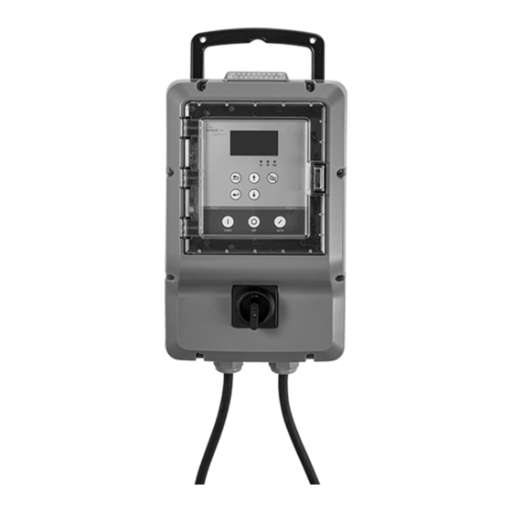
2 Product Description 1. Control box 2. Handle 3. Status lamp 4. On/off switch 5. Cable entry, pump 6. Cable entry, extra 7. Cable entry, power supply 8. Control module 2.5 Data plate Control box Serial No: “Bar Code” YYWWXXXXXXXXX Part No: “Bar Code”... -
Page 15: Function Description
3 Function Description 3 Function Description 3.1 Configuration Initial configuration Item Description Control box The control box is preconfigured for pumps with a specific voltage and current. Control module The control module must be configured to match the voltage and current of the pump. The control module can be configured with a configuration file or manually. -
Page 16: Standard Mode
3 Function Description 3.2.2 Standard mode The controller monitors sensors in the pump. There is no pump module installed in the junction box. Signals from the pump No signal from the pump Thermal contacts and leakage sensors connect to Internal thermal contact in the pump. the controller through the motor cable. -
Page 17: Hand Mode
3 Function Description • Hand • Off • Automatic 3.4.1 Hand mode The pump operates manually under the following conditions: • Signals from any installed float switches are ignored. • Detected snoring is ignored. • Minimum pause time is still applied. •... -
Page 18: Pause Time
3 Function Description 3.5 Pause time The pause time is the time that the pump is on standby in the hand mode or in the automatic mode. The pump does not operate during the pause time. The minimum and maximum pause time always have priority over other start and stop signals. -
Page 19: Alarms
3 Function Description 3.6 Alarms User Interface For more information about the LED behavior of the alarms, see on page 33. Priority level Priority level Description Class A • This alarm has the highest priority. • A Class A alarm stops the pump. It is not possible to start the pump until the alarm is inactive. - Page 20 3 Function Description Alarm Possible cause Remedy Priority level Reset Phase imbalance, There is a current Check the wiring Class A Automatic pump current imbalance in the and the phase leads of the connections to the pump. terminals. Phase imbalance, There is a voltage –...
-
Page 21: Installation
4 Installation 4 Installation 4.1 Precautions Before starting work, make sure that the safety instructions have been read and understood. DANGER: Electrical Hazard Before starting work on the unit, make sure that the unit and the control panel are isolated from the power supply and cannot be energized. -
Page 22: Electrical Installation
4 Installation • The unit complies with and is approved according to EMC Directive 2014/30/EU. In the European Union, equipment in which the unit is incorporated must also comply with the same directive. • The unit is approved as industrial equipment connected to a power network that is supplied by a dedicated high or medium voltage transformer. -
Page 23: Control Box
4 Installation 4.3 Control box 1. Power supply 2. Control box 3. Pump 4.3.1 Mechanical installation The control box is prepared to be installed on a wall. Select one of the following actions: Condition Action Installation 1. Drill four 6.5 mm (0.25 in) holes in the wall for the screws. with the pre- The image shows the drilling pattern. - Page 24 4 Installation 3. Open the control box. 4. Install the power cable and the pump cable through the cable entries. Parts For more information, see on page 9. 5. Connect the power supply leads to the power terminals. Terminals For more information, see on page 46.
-
Page 25: Optional Parts
4 Installation 8. Check that the cables are not pinched. 9. Close the control box. 4.3.3 Optional parts 4.3.3.1 Install the float switch • The extra cable entry of the control box must be open before starting the installation. Parts •... -
Page 26: Electrical Installation
4 Installation 184.5 mm (7.3 in) 184.5 mm (7.3 in) Ø 5 mm (0.2 in) 2. Make the opening. 3. Remove the back cover of the control module. 4. Push the back of the control module into the opening. 5. Tighten the back cover on the back of the control module with 12 screws. Use 4.6x16 mm (0.18x0.63 in) threaded screws for plastics. - Page 27 4 Installation 4.4.3.2 Cables NOTICE: The cables that are connected to the control module must meet the following requirements: • 0.75 mm² (AWG 18) • Minimum temperature rating: +105⁰C (+221⁰F) • Conductors must be copper. 4.4.3.3 Connection chart Terminals For more information, see on page 48.
-
Page 28: System Setup And Operation
5 System Setup and Operation 5 System Setup and Operation 5.1 Commissioning 1. Turn on the controller. 2. Select one of the following actions: Condition Action First start of a control box Run the Setup Wizard. The unit starts with the selected values. First start of a control 1. -
Page 29: Common Procedures
5 System Setup and Operation 5.3 Common procedures 5.3.1 Set the date and time 1. Go to Settings > Global > Date and time > Change date/time. 2. Change to the correct date and time. 5.3.2 Change the communication settings 1. -
Page 30: Set The Reference Power
5 System Setup and Operation 5.3.8 Set the reference power The controller uses the reference power of the pump to detect snoring. If the reference power is not known, then the parameter is configured in the Settings menu. Set the reference power. Condition Action Use of the default... -
Page 31: Maintenance
6 Maintenance 6 Maintenance 6.1 Precautions Before starting work, make sure that the safety instructions have been read and understood. DANGER: Electrical Hazard Before starting work on the unit, make sure that the unit and the control panel are isolated from the power supply and cannot be energized. -
Page 32: Cables
6 Maintenance • A short-circuit protection must be installed at the power supply to avoid electric shock and fire. The installation must follow the local rules and regulations. • An authorized local sales and service representative must replace the glass fuse in the Glass fuse properties control box. -
Page 33: Back Up The Application Settings
6 Maintenance d) Remove the WLAN unit. 2. Install the WLAN unit. a) Install the WLAN unit onto the printed circuit board. b) Install the back cover of the control module and tighten the screws. c) Connect the power leads. d) Install the holder. -
Page 34: Configuration
6 Maintenance 6.5 Configuration The configuration settings for the control module and the pump module are restored from the control module. 6.5.1 Configuration with a configuration file Contact the local sales and service representative to get the configuration file. 1. Save the configuration file to a USB drive. 2. -
Page 35: Cleaning
6 Maintenance Condition Action Software update: 1. Turn on the power to the control module. pump module 2. Go to Information > Controller information > About > Pump software upgrade. 3. Confirm the update. 6. Turn off the power. 7. Remove the USB drive. 6.7 Cleaning Make sure that the unit is clean from dust and dirt. -
Page 36: Troubleshooting
7 Troubleshooting 7 Troubleshooting 7.1 Precautions Before starting work, make sure that the safety instructions have been read and understood. DANGER: Electrical Hazard Troubleshooting a live control panel exposes personnel to hazardous voltages. Electrical troubleshooting must be done by a qualified electrician. DANGER: Electrical Hazard Before starting work on the unit, make sure that the unit and the control panel are isolated from the power supply and cannot be energized. -
Page 37: User Interface
8 User Interface 8 User Interface 8.1 LED indicators and buttons Table 1: LED indicators Position number Description Color Indication Pump status Green Automatic mode • The pump operates. • The pump is on standby. Hand mode • The pump operates. Yellow •... -
Page 38: Alarms
8 User Interface Position number Description Color Indication Pump status Constant green Automatic mode • The pump operates. Hand mode • The pump operates. Flashing green The pump is on standby. – The pump does not operate. Alarm There is a class A alarm. Yellow There is a class B alarm. - Page 39 8 User Interface Data plate For more information, see the Installation, Operation, and Maintenance manual of the pump. Part Description Product code The product code of the pump Product number The product number of the pump Serial number The serial number of the pump Curve number The curve number of the pump Number of phases...
-
Page 40: Controller Information
8 User Interface Part Description Pump thermal/FLS The state of the FLS • Open • Closed Controller temperature The temperature in the pump module Export Part Description Back up logs to USB The option to back up the log files to a USB drive 8.3.2 Controller information Communication WLAN... - Page 41 8 User Interface Controller I/O Part Description Voltage RMS The measured Voltage RMS values • L1 voltage • L2 voltage • L3 voltage • L1-L2 phase angle Power and current The measured power and current values • L1 current • L1 power •...
-
Page 42: Settings
8 User Interface Export Part Description Back up logs to USB The option to back up the log files to a USB drive 8.4 Settings Part Description Language A selection of all the available languages Language For more information, see on page 38. -
Page 43: Pump Control
8 User Interface 8.4.2 Pump control Part Default value Values Description Pump name – Four or more The option to change the name of the characters pump Site name – Four or more The option to change the name of the characters site Start condition... -
Page 44: Communication Settings
8 User Interface Alarm Default value Values Description 500 h Interval The delay from the time that the alarm is • 1–10000 h triggered, until the alarm is active again. Motor overtemperature Enabled Reset required • Disabled • Disabled The alarm resets automatically. -
Page 45: Global
8 User Interface Part Default value Values Description Slave address 1–247 The communication settings Baud 19200 • 1200 • 2400 • 4800 • 9600 • 19200 • 38400 • 57600 • 115200 Parity None • None • Even • Odd Number of data bits •... -
Page 46: Setup Wizard
8 User Interface Back up/restore Part Description Controller data plate The option to restore the controller ratings from an external USB drive • Restore from USB Pump data plate The option to restore the configuration of the pump data plate from an external USB drive •... - Page 47 8 User Interface Part Default value Values Description Start condition Timer • Timer The selection of the start condition of the automatic control mode • Float • Timer/Float Stop condition Snore • Snore The selection of the stop condition of the automatic control mode •...
-
Page 48: Technical Reference
9 Technical Reference 9 Technical Reference 9.1 Control box 9.1.1 Variants Part number Voltage Current Max short- Size Contactor Overload rating, V range, A circuit Bluetooth Bluetooth protection WLAN rating, A 8243500 8243510 380–690 0.8–2.7 Small AF16Z-30- EF19-2.7 01-21 8243502 8243512 380–690 1.9–6.3... -
Page 49: Environmental Requirements
9 Technical Reference Size Dimensions Large 1. 279.5 mm (11.0 in) 2. 440 mm (17.3 in) 3. 523 mm (20.6 in) 4. 209 mm (8.22 in) 9.1.3 Environmental requirements Parameter Value Operating temperature -20°C to 40°C (-4°F to 104°F) Maximum altitude Maximum 2000 m (6562 ft) Overvoltage category Category III... -
Page 50: Terminals
9 Technical Reference 9.1.6 Terminals GC ≥ 24 A GC ≤ 24 A Section Terminal Description Main lead Main lead Main lead Power cable Ground (earth) Ground check For AWG cables FS + Float switch FS – LS + Level sensor LS –... -
Page 51: Pareo Dcm 711 Control Module
9 Technical Reference 9.2 Pareo DCM 711 control module 9.2.1 Variants Part number Voltage rating, V Bluetooth Bluetooth WLAN 8261400 8261401 200–1000 9.2.2 Dimensions 1. 211.2 mm (8.3 in) 2. 223.6 mm (8.8 in) 3. 69.5 mm (2.7 in) 9.2.3 Environmental requirements Parameter Value Operating temperature... -
Page 52: Terminals
9 Technical Reference 9.2.5 Terminals Section Terminal Description USB Host, type A connector 500 mA Ethernet RJ45 10/100T +24 V Power, DC 500 mA, 24 VDC, SELV For more information, see on page 50. Tolerance: -10% to + 10% CT RED Analog input, AC CT BLACK 4 Current differential... -
Page 53: Standards And Approvals: Further Information
9 Technical Reference Section Terminal Description +24V RS-485 Modbus slave Cellular 120 R termination RS485 A 24 V Shield 250 mA cellular RS485 B 0V cellular 24 RL Y_COM 25 Common for all relays 30 VDC / 5A, (SELV) resistive RL Y_FWD 26 Output for forward contactor 250 VAC / 1A,... -
Page 54: Eu: Radio Equipment Directive
9.4 or Limited Power Source per UL 61010-1 or Class 2 per NEC. 9.3.3 EU: Radio Equipment Directive Hereby, Xylem Water Solutions Global Services AB declares that DCM 711 is in compliance with Directive 2014/53/EU. The full text of the EU Declaration of Conformity is available at the following internet address: http:// tpi.xyleminc.com. - Page 55 9 Technical Reference Operation is subject to the following two conditions: • This equipment or device may not cause harmful interference. • This equipment or device must accept any interference, including interference that may cause undesired operation. This product is not recommended for use at a distance of less than 20 cm from the human body.
- Page 56 For more information on how Xylem can help you, go to www.xylem.com Xylem Water Solutions Global Visit our Web site for the latest version of this document...
Need help?
Do you have a question about the FLYGT Pareo DCM 711 and is the answer not in the manual?
Questions and answers