Advertisement
Quick Links
Evaluates: MAX30001G
General Description
The MAX30001G evaluation kit (EV kit) provides a
single platform to evaluate the functionality and
features of the MAX30001G with Biopotential (ECG
and R-to-R) and Bioimpedance (BioZ) optimized for
Galvanic Skin Response (GSR) measurement capa-
bilities. The EV kit includes a MAX30001G evaluation
kit (EV kit) and a MAX32630FTHR Cortex-M4F micro-
controller for wearables. The MAX32630FTHR provides
power to the MAX30001G EV kit and contains the firm-
ware necessary to use the EV kit GUI program. The EV
kit ships with jumpers installed and supply voltages set to
typical operating values. Optional connections exist which
can be shunted to make use of different functionalities.
This EV kit is not a medical device.
Ordering Information
appears at end of data sheet.
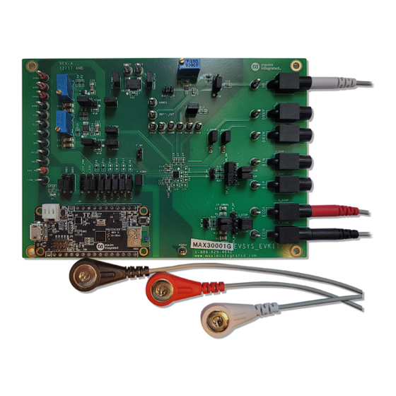
MAX30001G EV Kit Board Photo
Windows is a registered trademark and registered service mark of Microsoft Corporation.
© 2021 Analog Devices, Inc. All rights reserved. Trademarks and registered trademarks are the property of their respective owners.
One Analog Way, Wilmington, MA 01887 U.S.A.
Click
here
to ask an associate for production status of specific part numbers.
Features
● Convenient Platform to Evaluate the MAX30001G
● Many Easy-to-Reach Test Points
● Measure Individual Supply Currents
● Touchproof Cable Connectors
● Windows
● Fully Assembled and Tested
● Facilitates IEC 60601-2-47 Compliance Testing
● Ultra-Low-Power Design
EV kit Contents
● MAX30001G EV kit
● MAX32630FTHR
● USB A to micro-USB cable
● Three (3) ECG cables
|
Tel: 781.329.4700
|
MAX30001G Evaluation Kit
®
7/8/10 Compatible GUI software
© 2021 Analog Devices, Inc. All rights reserved.
319-100854; Rev 0; 11/21
Advertisement

Related Manuals for Analog Devices MAX30001G


Summary of Contents for Analog Devices MAX30001G
- Page 1 Windows is a registered trademark and registered service mark of Microsoft Corporation. 319-100854; Rev 0; 11/21 © 2021 Analog Devices, Inc. All rights reserved. Trademarks and registered trademarks are the property of their respective owners. One Analog Way, Wilmington, MA 01887 U.S.A.
-
Page 2: Quick Start
Micro-USB cable natively, go to Start | All Programs. Look for the ● Windows PC with USB port MAX30001G EVKitSoftware folder and click on the MAX30001G EVKitSoftware.EXE file inside the folder. Procedure 9) After the initial splash screen, when the GUI The EV kit is fully assembled and tested. - Page 3 MAX30001G Evaluation Kit Evaluates: MAX30001G Figure 1. The Connection Issue Dialog Box Appears If The GUI Does Not Detect the EV Kit. Figure 2. The Connection Screen Allows The User to Select Which COM Port Contains the EV Kit. Analog Devices │ 3...
-
Page 4: Tab Control
Changing these interactive Maximum Time allows the user to select how many controls triggers a write operation to the MAX30001G to seconds of data they want to be shown on the plot at update the register contents. Likewise, these controls are one time. - Page 5 MAX30001G Evaluation Kit Evaluates: MAX30001G Figure 4. Saving a Log File. Analog Devices │ 5 www.analog.com...
- Page 6 MAX30001G Evaluation Kit Evaluates: MAX30001G Home Tab The Home tab (Figure 5) provides an overview of the MAX30001G EV kit’s features. Figure 5. MAX30001G EV Kit GUI Home Tab Analog Devices │ 6 www.analog.com...
- Page 7 ADC sampling rate, are found in the ECG Channel block diagram. The R-to-R box configures R-to-R detection using the ECG input data. A detailed description of all ECG channel configuration settings and R-to-R functionality can be found in the MAX30001G data sheet.
- Page 8 ECG Bias, Resistive Bias Value set to 100MΩ, Positive Input Bias Enable and Negative Input Bias Enable set to Connected. DC Lead-Off Check, ULP Lead-On Check, and Calibration Test Voltage functionalities are detailed further in depth in the MAX30001G data sheet. Figure 7. MAX30001G EV Kit ECG MUX Tab Analog Devices │...
- Page 9 ECG Channel tab, controls on this tab configure the filters and amplifiers of the device’s BioZ channel. A detailed description of all BioZ channel configuration settings can be found in the MAX30001G data sheet. Figure 8. MAX30001G EV Kit BioZ Channel Tab.
- Page 10 As part of the BioZ self-test, a resistive load is available on the DRVP and DRVN pins. Clicking on Selectable Resistive Load will bring the GUI to the BioZ Load tab. Refer to the full MAX30001G data sheet for detailed descriptions of the BioZ MUX configurations.
- Page 11 Resistance Built-In-Self-Test (RMOD BIST) block. RMOD BIST Enable configures the BioZ channel to connect or detach the resistive load. Refer to the full MAX30001G data sheet for a description of the modulated resistive load. Figure 10. MAX30001G EV Kit BioZ Load Tab.
- Page 12 BioZ is disabled, the plot area will be occupied entirely by the ECG waveform. Likewise, if BioZ is enabled instead of ECG, the BioZ plot is maximized. When both measurement channels are enabled, the plotting space contains both ECG and BioZ data. Figure 11.MAX30001G EV Kit Plots Tab. Analog Devices │ 12 www.analog.com...
- Page 13 MAX30001G Evaluation Kit Evaluates: MAX30001G R-to-R data is shown in the ECG plot. R-to-R peak detection is indicated by a red circle at the peaks of the R waves. Heart rate information gathered from R-to-R detection can be found in the Heart Rate (from R-to-R) box below the plot- ting area.
- Page 14 Erase buttons, respectively. Pressing Advanced displays the current register contents to be written to an SD card The MAX30001G EV kit can use the SD card read/write setting file when Write is pressed. After confirming the functionality of the MAX32630FTHR to store and recall register configurations, select the type of data to save in log data to and from a microSD card.
- Page 15 The Registers tab (Figure 14) provides more direct access to the internal registers of the MAX30001G. From this tab, it is possible to read the contents of individual registers and to manually enter the desired bit settings for a write operation.
- Page 16 15) is accessible through the Options ToolStrip menu. The tab provides manual communication with the MAX30001G to bypass the GUI controls entirely. Enter the register address, as a hexadecimal value, in the Address field. Read data from a register by pressing the ReadReg button and the data will populate the Read Data field. To write data, enter the hexadecimal value in the Write Data field and press the WriteReg button.
- Page 17 32.768kHz crystal oscillator (U5) supplies FCLK to the IC, but external frequency generation is supported. Note: Ball C2 on the MAX30001G is called N.C. and should not be connected to anything. This PCB does The EV kit utilizes the MAX32630FTHR Cortex-M4F route this signal to the testpoint labeled AOUT.
- Page 18 MAX30001G Evaluation Kit Evaluates: MAX30001G Table 1. Description Of Jumpers (continued) JUMPER SHUNT POSITION DESCRIPTION Supply 1.8V to J_AVDD and J_DVDD from the MAX32630FTHR. 2-3* Supply an adjustable voltage to J_AVDD and J_DVDD from an LDO (U2). Supply 3.3V to J_OVDD and OVDDX from the MAX32630FTHR.
- Page 19 MAX30001G Evaluation Kit Evaluates: MAX30001G MAX 32630FTHR INTB INT2B AVDD DVDD OVDD J_AVDD INTB INT2B AVDD J_DVDD DVDD OVDD J_OVDD EP_UNBAL 0Ω J_ECGP ECGP ECGP EP_E N 0Ω J_ECGN ECGN ECGN EN_UNBAL 0Ω J_BIP MAX30001G BP_B N 100Ω 0Ω J_BIN...
- Page 20 ECG and BioZ lines. Capacitors C8 and C25 can create an The MAX30001G EV kit can be powered from an external external common mode filter for the ECG and BioZ lines, supply or directly from the MAX32630FTHR. To use an respectively.
- Page 21 MAX30001G Evaluation Kit Evaluates: MAX30001G EP_UNBAL 0Ω J_ECGP ECGP ECGP EP_EN J_ECGN 0Ω ECGN ECGN EN_UNBAL EP_BP EN_BN J_BIP 0Ω BP_BN 100Ω J_BIN 0Ω DP_BP DN_BN 220nF J_DRVP DRVP DRVP 220nF J_DRVN DRVN DRVN Figure 17. Default Measurement Channel Jumper Configurations EP_UNBAL 0Ω...
- Page 22 MAX30001G Evaluation Kit Evaluates: MAX30001G Galvanic Skin Response Measurement When using the BioZ channel for GSR measurements, two dry electrodes should be used to focus the measurement on the skin’s contact impedance. A lower current generator frequency, such as 125Hz, 250Hz, or 500Hz should be selected.
-
Page 23: Ordering Information
Susuma www.susuma-usa.com Taiyo Yuden www.t-yuden.com www.global.tdk.com TE Connectivity www.te.com Vishay Dale www.vishay.com Note: Indicate that you are using the MAX30001G EV kit when contacting these component suppliers. Ordering Information PART TYPE MAX30001GEVKIT# EV kit Analog Devices │ 23 www.analog.com... - Page 24 MAX30001G Evaluation Kit Evaluates: MAX30001G MAX30001G_EVSYS_EVKIT Bill of Materials ITEM REF_DES DNI/DNP MFG PART # MANUFACTURER VALUE DESCRIPTION 1V8, 3V3, BB_SEL, GND1, GND2, J_CSB, J_EXT_PWR, CONNECTOR; MALE; THROUGH HOLE; BREAKAWAY; — PCC03SAAN SULLINS PCC03SAAN J_INT2B, J_INTB, STRAIGHT THROUGH; 3PINS; -65 DEGC TO +125 DEGC...
- Page 25 MAX30001G Evaluation Kit Evaluates: MAX30001G MAX30001G_EVSYS_EVKIT Bill of Materials (continued) ITEM REF_DES DNI/DNP MFG PART # MANUFACTURER VALUE DESCRIPTION R1, R31 — ERA-6ARW513 PANASONIC RES; SMT (0805); 51K; 0.05%; +/-10PPM/DEGC; 0.1250W CRCW06031K00FK; VISHAY; R2, R3 — ERJ-3EKF1001; PANASONIC; RES; SMT (0603); 1K; 1%; +/-100PPM/DEGC; 0.1000W...
- Page 26 MAX30001G Evaluation Kit Evaluates: MAX30001G MAX30001G_EVSYS_EV Kit Schematic Diagrams Analog Devices │ 26 www.analog.com...
- Page 27 MAX30001G Evaluation Kit Evaluates: MAX30001G MAX30001G_EVSYS_EV Kit Schematic Diagrams (continued) Analog Devices │ 27 www.analog.com...
- Page 28 MAX30001G Evaluation Kit Evaluates: MAX30001G MAX30001G_EVSYS_EVKIT PCB Layout Diagrams 1.0’’ MAX30001G_EVSYS_EVKIT—Top Silkscreen Analog Devices │ 28 www.analog.com...
- Page 29 MAX30001G Evaluation Kit Evaluates: MAX30001G MAX30001G_EVSYS_EVKIT PCB Layout Diagrams (continued) 1.0’’ MAX30001G_EVSYS_EVKIT—Top View Analog Devices │ 29 www.analog.com...
- Page 30 MAX30001G Evaluation Kit Evaluates: MAX30001G MAX30001G_EVSYS_EVKIT PCB Layout Diagrams (continued) 1.0’’ MAX30001G_EVSYS_EVKIT—Layer 2 Analog Devices │ 30 www.analog.com...
- Page 31 MAX30001G Evaluation Kit Evaluates: MAX30001G MAX30001G_EVSYS_EVKIT PCB Layout Diagrams (continued) 1.0’’ MAX30001G_EVSYS_EVKIT—Layer 3 Analog Devices │ 31 www.analog.com...
- Page 32 MAX30001G Evaluation Kit Evaluates: MAX30001G MAX30001G_EVSYS_EVKIT PCB Layout Diagrams (continued) 1.0’’ MAX30001G_EVSYS_EVKIT—Bottom View Analog Devices │ 32 www.analog.com...
- Page 33 MAX30001G Evaluation Kit Evaluates: MAX30001G MAX30001G_EVSYS_EVKIT PCB Layout Diagrams (continued) 1.0’’ MAX30001G_EVSYS_EVKIT—Bottom Silkscreen Analog Devices │ 33 www.analog.com...
-
Page 34: Revision History
Information furnished by Analog Devices is believed to be accurate and reliable. However, no responsibility is assumed by Analog Devices for its use, nor for any infringements of patents or other rights of third parties that may result from its use.Specifications subject to change without notice. No license is granted by implicationor otherwise under any patent or patent rights of Analog Devices.
Need help?
Do you have a question about the MAX30001G and is the answer not in the manual?
Questions and answers