Advertisement
Quick Links
General Description
The MAX42410 evaluation kit (EV kit) provide a proven
design to evaluate the MAX42410 synchronous buck
converter with 10μA quiescent current. The EV kit comes
with a MAX42410AFOB+ (1.5MHz) installed, as well as
various test points and jumpers for evaluation. The EV kit
output voltage is variable and is set to 3.3V. It can be easily
configured to 0.8V to 6V (1.5MHz) or up to 10V (400kHz)
with minimum component changes. The EV kit is designed
to deliver up to 10A with input voltage 4.5V to 36V. The
output voltage quality can be monitored by observing the
PGOOD signal.
Benefits and Features
•
Input Supply Range from 4.5V to 36V
•
Adjustable output voltage from 0.8V to 6V (1.5MHz)
•
Delivers Up to 8A/10A
•
Frequency-Synchronization Input
•
Enable Input
•
Voltage Monitoring PGOOD Output Available
•
Proven PCB Layout
•
Fully Assembled and Tested
Ordering Information
appears at end of data sheet.
319-101037; Rev 0; 11/23
O n e A n a l o g W a y , W i l m i n g t o n , M A 0 1 8 8 7 - 2 3 5 6 , U . S . A .
Evaluation Board User Guide
MAX42410 Evaluation Kit
Evaluates: MAX42408/MAX42410
Quick Start
Required Equipment
•
MAX42410 EV kit
•
36V, 10A DC power supply (PS)
•
Appropriate resistive load, or an electronic load that
can sink 10A
•
Digital multimeter (DMM)
•
Oscilloscope
Procedure
The EV kit is fully assembled and tested. Do the following
steps to verify board operation:
1. Verify that all jumpers are in their default positions, as
shown in
Table
2. Connect the positive and negative terminals of the
power supply to the VSUP and GND test pads,
respectively.
3. Set the power-supply voltage to 14V.
4. Turn on the power supply.
5. Using the DMM, verify the OUT is approximately 3.3V.
6. Verify that the switching frequency is approximately
1.5MHz by monitoring the inductor switching voltage
with the oscilloscope.
7. Turn off the power supply.
8. Connect the positive and negative terminals of the
electronic load to VOUT and GND2, respectively.
9. Set the electronic load to the required current at or
below 10A or use an equivalent resistive load with an
appropriate power rating.
10. Adjust current-limit on the power supply as necessary.
11. Turn on the power supply and electronic load.
12. Verify that voltage across the VOUT and GND2 PCB
pads is 3.3V ± 2%.
DOCUMENT FEEDBACK
T e l : 7 8 1 . 3 2 9 . 4 7 0 0
© 2 0 2 3 A n a l o g D e v i c e s , I n c . A l l r i g h t s r e s e r v e d .
1.
TECHNICAL SUPPORT
Advertisement

Related Manuals for Analog Devices MAX42410


Summary of Contents for Analog Devices MAX42410
- Page 1 MAX42410 Evaluation Kit Evaluates: MAX42408/MAX42410 Quick Start General Description Required Equipment The MAX42410 evaluation kit (EV kit) provide a proven design to evaluate the MAX42410 synchronous buck • MAX42410 EV kit converter with 10μA quiescent current. The EV kit comes •...
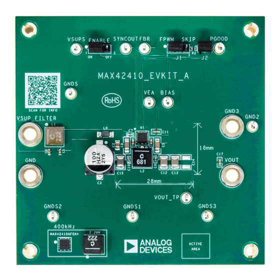
- Page 2 MAX42410 Evaluation Kit Evaluation Board User Guide EV Kit Board Photos Figure 1. MAX42410 EV Kit Board Photo—Top Figure 2. MAX42410 EV Kit Board Photo—Bottom analog.com Rev. 0 2 of 10...
- Page 3 This MAX42410 EV kit data sheet must be used with the MAX42408/MAX42410 IC data sheet. The MAX42410 EV kit provides a proven layout for the MAX42408/MAX42410 synchronous buck regulator IC. The IC accepts input voltages as high as 36V and delivers up to 10A. The EV kit can handle an input supply transient up to 42V.
-
Page 4: Ordering Information
MAX42410 Evaluation Kit Evaluation Board User Guide Table 1. Jumper Connection Guide JUMPER DEFAULT CONNECTION FEATURE ENABLE Buck enabled Forced PWM Installed PGOOD pulled up to BIAS. Ordering Information PART TYPE MAX42410EVKIT# 3.3V/1.5MHz EV kit #Denotes RoHS-compliant. analog.com Rev. 0... - Page 5 MAX42410 Evaluation Kit Evaluation Board User Guide MAX42410 EV Kit Bill of Materials PART MFG PART # MANUFACTURER VALUE DESCRIPTION 2.2UH XGL6060-222ME COILCRAFT 2.2UH INDUCTOR; SMT; COMPOSITE; 2.2UH; 20%; 17.2A BIAS, FBR, GND2, 5012 KEYSTONE TEST POINT; PIN GNDS, GNDS1- DIA=0.125IN;...
- Page 6 MAX42410 Evaluation Kit Evaluation Board User Guide MAX42410 EV Kit Bill of Materials (continued) PART MFG PART # MANUFACTURER VALUE DESCRIPTION PEC02SAAN SULLINS PEC02SAAN CONNECTOR; MALE; THROUGH HOLE; BREAKAWAY; STRAIGHT; 2PINS FBMJ4516HS720N TAIYO YUDEN INDUCTOR; SMT (1806); FERRITE-BEAD; 72 IMPEDANCE AT 100MHZ;...
- Page 7 MAX42410 Evaluation Kit Evaluation Board User Guide MAX42410 EV Kit Schematic analog.com Rev. 0 7 of 10...
- Page 8 MAX42410 Evaluation Kit Evaluation Board User Guide MAX42410 EV Kit PCB Layout MAX42410 EV Kit Component Placement Guide—Top MAX42410 EV Kit PCB Layout—Layer 2 Silkscreen MAX42410 EV Kit PCB Layout—Top MAX42410 EV Kit PCB Layout—Layer 3 analog.com Rev. 0 8 of 10...
-
Page 9: Revision History
MAX42410 Evaluation Kit Evaluation Board User Guide MAX42410 EV Kit PCB Layout (Continued) MAX42410 EV Kit PCB Layout—Bottom MAX42410 EV Kit Component Placement Guide—Bottom Silkscreen Revision History REVISION REVISION DESCRIPTION PAGES NUMBER DATE CHANGED 11/23 Initial release — analog.com Rev. 0... - Page 10 Evaluation Board User Guide ASSUMED BY ANALOG DEVICES FOR ITS USE, NOR FOR ANY INFRINGEMENTS OF PATENTS OR OTHER RIGHTS OF THIRD PARTIES THAT MAY RESULT FROM ITS USE. SPECIFICATIONS ARE SUBJECT TO CHANGE WITHOUT NOTICE. NO LICENCE, EITHER EXPRESSED OR...
Need help?
Do you have a question about the MAX42410 and is the answer not in the manual?
Questions and answers