Advertisement
Quick Links
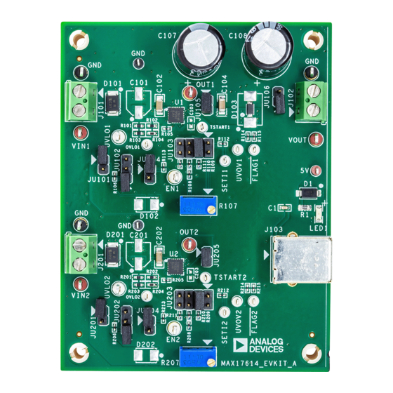
MAX17614 Evaluation Kit
General Description
The MAX17614 evaluation kit (EV kit) is a fully
assembled and tested circuit board that demonstrates
the MAX17614 ideal diode/power source selector in a
20-pin TQFN-EP package. The EV kit allows two power
sources to be connected as inputs. The load gets power
from the higher voltage power source for ideal diode
applications. For power source selector applications, the
load gets power from either of the two power sources by
driving respective EN pins. The EV kit configurations
allow independent settings for the two instances to
demonstrate adjustable overvoltage, undervoltage,
reverse current blocking, three current-limit types
(autoretry, continuous, and latch-off) with different
programmable current-limit thresholds (from 0.15A to
3A). For more details about the IC benefits and features,
refer to the MAX17614 IC data sheet.
© 2023 Analog Devices, Inc. All rights reserved. Trademarks and registered trademarks are the property of their respective owners.
Click
here
to ask an associate for production status of specific part numbers.
Evaluates: MAX17614 in Ideal
Diode/Power Source Selector
Features
• 4.5V to 40V Operating Input Voltage Range
(Remove the TVS Diodes D101, D201, and Open
Jumpers JU101, JU201 to Extend the Operating
Range up to 60V)
• 40V TVS Diodes (D101 and D201) across the Input
Terminals
• Schottky Diode (D103) across the Output Terminals
• Evaluates Undervoltage Lockout (UVLO1, UVLO2),
Overvoltage Lockout (OVLO1, OVLO2), Three
Current-Limit Types, and Current-Limit Thresholds
• UVLO Programmed to 4.5V for Both Input Voltages
• OVLO Programmed to 40.2V for Both Input
Voltages
• Internally Pulled-Up Active High Enable Inputs
• Jumper-Configurable Current Limits (Selected as
0.3A by Default)
• Jumper-Configurable (JU102, JU202) Current-Limit
Types (Selected as Autoretry by Default)
• Programmable Startup Blanking Times (C103,
C203)
• Fault Indication Signals (UVOV1, UVOV2, FLAG1,
FLAG2)
• Proven PCB Layout
• Fully Assembled and Tested
Ordering Information
Applications
appears at end of data sheet.
319-101000; Rev 0; 6/23
Advertisement

Related Manuals for Analog Devices MAX17614


Summary of Contents for Analog Devices MAX17614
- Page 1 • Proven PCB Layout • Fully Assembled and Tested Ordering Information appears at end of data sheet. 319-101000; Rev 0; 6/23 © 2023 Analog Devices, Inc. All rights reserved. Trademarks and registered trademarks are the property of their respective owners.
-
Page 2: Quick Start
USB power source or 5V DC power supply Equipment Setup and Test Procedure A typical bench setup for MAX17614 EV Kit is shown in Figure 1. The EV kit is fully assembled and tested. Follow the steps to verify board operation. - Page 3 Evaluates: MAX17614 in Ideal MAX17614 Evaluation Kit Diode/Power Source Selector Applications 8. Gradually decrease VIN1 and verify that VOUT voltage (J102) is restored back when the input voltage reaches approximately 38.8V. Also check that UVOV1 status changes from 5V to 0V.
- Page 4 Power Source Selector The EN pin of the MAX17614 allows a system microcontroller to turn ON/OFF power to the load, thus enabling the system to select a power source based on operating conditions. Configure shunt position not installed for jumpers JU104 and JU204 and drive the EN pins of devices U1 and U2 high or low for selection of input supply voltages.
-
Page 5: Current Monitoring
*Default Position Current Monitoring The MAX17614 features read out of the current flowing from IN-to-OUT. The current from IN-to-OUT is mirrored with a ratio of 3032 (C ) and flows out through the SETI pin, into the external current-limit resistor. The voltage on the SETI... - Page 6 × 5µ TSTART2 C203 ≥ × 5µ For more details about startup requirements, refer to the MAX17614 IC data sheet. Output Load Capacitor Configure Jumper JU106 to connect output to 470µF capacitors (see Table Table 5. Output Load Capacitor (JU106) Settings...
- Page 7 Evaluates: MAX17614 in Ideal MAX17614 Evaluation Kit Diode/Power Source Selector Applications MAX17614 EV Kit Typical Operating Characteristics = 1µF, C = 4.7µF, V = 24V, V = 20V, V = 5V, I = 3A, CLMODE1 = CLMODE2 = Autoretry, LIMIT1 LIMIT2 = 40.2V, T...
- Page 8 JU105, JU205, respectively) IN1_OVR IN2_OVR Component Suppliers SUPPLIER WEBSITE Murata Americas www.murata.com Vishay www.vishay.com Panasonic www.panasonic.com Taiyo Yuden www.taiyoyuden.com Diodes Incorporated www.diodes.com Bourns, Inc. www.bourns.com Note: Indicate that you are using MAX17614 when contacting these component suppliers. www.analog.com Analog Devices | 8...
- Page 9 Evaluates: MAX17614 in Ideal MAX17614 Evaluation Kit Diode/Power Source Selector Applications MAX17614 EV Kit Bill of Materials S.NO PART REFERENCE DESCRIPTION MANUFACTURER PART NUMBER 1µF 10% 25V X7R ceramic capacitor (0603) TAIYO YUDEN TMK107B7105KA 1µF 10% 100V X7R ceramic capacitor...
- Page 10 Evaluates: MAX17614 in Ideal MAX17614 Evaluation Kit Diode/Power Source Selector Applications S.NO PART REFERENCE DESCRIPTION MANUFACTURER PART NUMBER SULLINS ELECTRONICS CORP. SU1-SU11 Shunt Connector, Black Closed Top STC02SYAN J101, J102, J201 2-Pin Green PC Terminal Block TE CONNECTIVITY 282837-2 J103...
- Page 11 Evaluates: MAX17614 in Ideal MAX17614 Evaluation Kit Diode/Power Source Selector Applications MAX17614 EV Kit Schematics www.analog.com Analog Devices | 11...
- Page 12 Evaluates: MAX17614 in Ideal MAX17614 Evaluation Kit Diode/Power Source Selector Applications www.analog.com Analog Devices | 12...
- Page 13 Evaluates: MAX17614 in Ideal MAX17614 Evaluation Kit Diode/Power Source Selector Applications MAX17614 EV Kit PCB Layout MAX17614 EV Kit PCB Layout—Top Layer MAX17614 EV Kit PCB Layout—Top Silkscreen MAX17614 EV Kit PCB Layout—Layer 2 MAX17614 EV Kit PCB Layout—Layer 3 www.analog.com...
-
Page 14: Ordering Information
Evaluates: MAX17614 in Ideal MAX17614 Evaluation Kit Diode/Power Source Selector Applications MAX17614 EV Kit PCB Layout (Continued) MAX17614 EV Kit PCB Layout—Bottom Layer MAX17614 EV Kit PCB Layout—Bottom Silkscreen Ordering Information PART TYPE MAX17614EVKIT# EV Kit #Denotes RoHS compliance. www.analog.com... -
Page 15: Revision History
Information furnished by Analog Devices is believed to be accurate and reliable. However, no responsibility is assumed by Analog Devices for its use, nor for any infringements of patents or other rights of third parties that may result from its use. Specifications subject to change without notice. No license is granted by implication or otherwise under any patent or patent rights of Analog Devices.
Need help?
Do you have a question about the MAX17614 and is the answer not in the manual?
Questions and answers