Table of Contents
Advertisement
Quick Links
MAX31334 Evaluation Kit
General Description
The MAX31334 shield evaluation kit (EV kit) is a fully
assembled and tested PCB to evaluate the MAX31334, an
ultra-low power, low-cost, real-time clock (RTC) with
integrated power switch, I
management. The shield EV kit operates from a single
supply (either from USB or external power supply) and the
onboard crystal provides a 32.768kHz clock signal. This
device is accessed through an I
by a MAX32625PICO board connected to a PC by a USB
port.
The MAX31334 shield EV kit provides the hardware and
software graphic user interface (GUI) necessary to
evaluate the MAX31334. The kit includes an installed
MAX31334. It connects to the PC through a MAX32625
PICO board and a micro-USB cable.
Features
•
Easy Evaluation of the MAX31334
•
+1.1V to +5.5V Single-Supply Operation
•
Proven PCB Layout
•
Fully Assembled and Tested
EV Kit Contents
•
Assembled circuit board, including the MAX31334
•
Assembled MAX32625PICO I
•
Micro-USB cable
MAX31334 EV Kit Files
FILE
MAX31334EVKIT.exe
Installs EV kit files onto computer
Ordering Information
appears at end of data sheet.
Windows is a registered trademark and registered service mark
of Microsoft Corporation.
One Analog Way, Wilmington, MA 01887 U.S.A. | Tel: 781.329.4700 | © 2022 Analog Devices, Inc. All rights reserved.
2
C interface, and power
2
C serial interface provided
2
C circuit board
DESCRIPTION
Evaluates: MAX31334
Quick Start
Required Equipment
•
One DC power supply capable of supplying +1.1V to
+5.5V (typical +3.0V used in the following instructions)
•
One pico ammeter for measuring the current
•
One oscilloscope
•
One micro-USB cable
•
One assembled MAX32625PICO I
•
One MAX31334 shield EV kit
Procedure
The EV kit is fully assembled and tested. Note: In the
following sections, software-related items are identified by
bolding. Text in bold refers to items directly from the
evaluation software. Text in bold and underlined refers to
items from the Windows® operating system. Follow these
steps to verify board operation.
1. Place the MAX31334 EV kit on a nonconductive surface to
ensure that nothing on the PCB gets shorted to the
workspace.
2. Set the jumpers to their default positions as shown in
1
to test the WLP package variant (U1) of MAX31334.
3. With the output of the power supply set to +3.0V and
disabled, connect the positive terminal of the DC
supply to VCC_EXT and the negative terminal to the
GND of the EV kit.
4. Connect the MAX32625PICO I
EV kit at its location
(Figure
5. Connect
the
micro-USB
MAX32625PICO board and PC/laptop.
6. Enable the +3.0V DC power supply.
7. Click on the Design and Development tab on the
product folder page
to download the latest version of
the MAX31334 real-time clock EV kit software, then run
the control software.
8. Open the MAX31334 real-time clock EV kit software;
this displays the MAX31334 Real-Time Clock EV Kit
Software Monitor page and shows "USB Connected"
in the lower right corner.
9. Verify that the clock has started counting by checking
the "Auto Update" box under Real Time Monitoring.
10. Configure the desired date and time in the Date/Time
Configuration section and click the SET button to
update it in the Real Time Monitoring section.
2
C circuit board
Table
2
C circuit board to the
1).
cable
between
the
319-100946; Rev 0; 8/22
Advertisement
Table of Contents

Related Manuals for Analog Devices MAX31334


Summary of Contents for Analog Devices MAX31334
- Page 1 10. Configure the desired date and time in the Date/Time Configuration section and click the SET button to update it in the Real Time Monitoring section. 319-100946; Rev 0; 8/22 One Analog Way, Wilmington, MA 01887 U.S.A. | Tel: 781.329.4700 | © 2022 Analog Devices, Inc. All rights reserved.
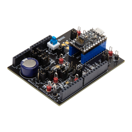
- Page 2 MAX31334 Evaluation Kit Evaluates: MAX31334 EV Kit Photo Figure 1. MAX31334 EV Kit Board Connections www.analog.com Analog Devices | 2...
- Page 3 MAX31334 Evaluation Kit Evaluates: MAX31334 Table 1. Jumper Connection Guide SHUNT JUMPER DESCRIPTION POSITION 1–2* Connects VBAT pin to TP2. 1–3 Connects VBAT pin to GND. 1–4 Connects VBAT pin to supercapacitor. 1–2* System VCC is powered by VCC_EXT at TP5.
-
Page 4: Detailed Description
It features an integrated high-side power pass switch that enables ultra-low- power idle modes on duty-cycled applications by disconnecting power to other devices on the system. The MAX31334 supports a wide range of 32.768kHz crystals. Crystals with any capacitive loading (CL) spec can be used, which broadens the pool of usable crystals for this device. -
Page 5: Timer Interrupt
The TimeStamp Overwrite toggle button can be used to log the first four events or the last four events. Using the RESET button clears all the four TimeStamp Registers. Refer to the TimeStamp section in the MAX31334 data sheet for more information. RAM Register Mode On the TimeStamp tab in the TimeStamp Configuration section, disable the TimeStamp Enable toggle button (default) to use the TimeStamp Mode. - Page 6 MAX31334 Evaluation Kit Evaluates: MAX31334 MAX31334 EV Kit Bill of Materials REF DES MFG PART # VALUE DESCRIPTION C2, C7, C8, C15 CL05B105KQ5NQNC CAP; SMT (0402) C3, C5, C9, C16-C18 CL05B104KQ5NNN 0.1UF CAP; SMT (0402) C4, C11, C13, C19 C1005X7R1C104K050BC 0.1UF...
- Page 7 MAX31334 Evaluation Kit Evaluates: MAX31334 MAX31334 EV Kit Schematic www.analog.com Analog Devices | 7...
- Page 8 MAX31334 Evaluation Kit Evaluates: MAX31334 MAX31334 EV Kit PCB Layout MAX31334 EV Kit PCB Layout—Top Silkscreen MAX31334 EV Kit PCB Layout—Top Layer MAX31334 EV Kit PCB Layout—Bottom Layer MAX31334 EV Kit PCB Layout— Bottom Silkscreen www.analog.com Analog Devices | 8...
-
Page 9: Revision History
Information furnished by Analog Devices is believed to be accurate and reliable. However, no responsibility is assumed by Analog Devices for its use, nor for any infringements of patents or other rights of third parties that may result from its use. Specifications subject to change without notice. No license is granted by implication or otherwise under any patent or patent rights of Analog Devices.
Need help?
Do you have a question about the MAX31334 and is the answer not in the manual?
Questions and answers