Table of Contents
Advertisement
Quick Links
Evaluates: MAX14916
General Description
The MAX14916PMB (peripheral module board) provides
the hardware to evaluate the MAX14916 Octal 1A / Quad
2A industrial high-side switch with diagnostics. Refer to
the MAX14916 IC data sheet for detailed information on
the operation of the IC. The module takes advantage of
the features in the MAX14916, which allow each channel
to independently be toggled on and off and continuously
monitored for faults. Note the module provides a
subset of the MAX14916 features. For greater flexibility,
refer to the MAX14916 evaluation kit.
The MAX14916PMB# has a 12-pin Pmod™-compatible
connector for serial peripheral interface (SPI) commu-
nication. The peripheral module can be used in various
ways; Analog Devices sells low-cost USB2PMB2#
and USB2GPIO# adapter boards that use the Munich
GUI software for SPI communication through a USB
cable. This is not included with this board but is availa-
ble from Analog Devices or one of its distributors.
Alternatively,
use
any
programmable gate array (FPGA) with a 12-pin Pmod-
compatible connector for SPI communication.
The PCB dimension is 62mm long x 22.6mm wide, with
the width determined by the size of the DO terminal block.
Ordering Information
appears at end of data sheet.
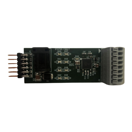
Figure 1. MAX14916PMB# Board Photo
Pmod is a registered trademark of Digilent Inc.
©
2022 Analog Devices, Inc. All rights reserved. Trademarks and registered trademarks are the property of their respective owners.
One Analog Way, Wilmington, MA 01887 U.S.A.
Click
microcontroller
or
field
|
Tel: 781.329.4700
here
to ask an associate for production status of specific part numbers.
Features
● Easy Evaluation of the MAX14916
● Internal Clamps for Fast Inductive Load
Demagnetization
● Individual Channel Fault Detection
● Supports Load Currents of up to 2.4A per Channel
● Works with USB2PMB2# or USB2GPIO# Adapter
and Munich GUI Software
● Fully Assembled and Tested
● Proven PCB Layout
● RoHS Compliant
Contents
● MAX14916PMB# with the MAX14916AFM+
● 24V DC (2.71A max.) power adapter
MAX14916PMB EV Kit Files
FILE
Munich
GUISetupV2.26.exe
or later
|
© 2022 Analog Devices, Inc. All rights reserved.
MAX14916PMB
DESCRIPTION
Munich GUI software for use with
the USB2PMB2# or USB2GPIO#
adapter
319-100958; Rev 0; 10/22
Advertisement
Table of Contents

Related Manuals for Analog Devices MAX14916PMB


Summary of Contents for Analog Devices MAX14916PMB
- Page 1 Pmod is a registered trademark of Digilent Inc. 319-100958; Rev 0; 10/22 © 2022 Analog Devices, Inc. All rights reserved. Trademarks and registered trademarks are the property of their respective owners. One Analog Way, Wilmington, MA 01887 U.S.A. Tel: 781.329.4700...
-
Page 2: Quick Start
Munich GUI software. Text in bold and underline files directory. refers to items from the MS Windows operating system. 5) Connect the 24V DC power adapter to J2 of the MAX14916PMB# to power up the board. The V Procedure DDOK LED (DS9 - green) turns on. - Page 3 Disconnected in the bottom right meter reads 24V. corner. To configure the MAX14916PMB#, go to the 12) Observe that when the output channel is turned on Device tab, select Industrial Digital, then select the and is shorted to GND, the Status LED turns off MAX14916PMB.
- Page 4 25ºC ambient temperature. For full details about the high- face. An optional USB2PMB2# or USB2GPIO# adapter side switch characteristics, refer to the MAX14916 IC data sheet. Figure 4. MAX14916PMB# Connected in Munich GUI (Short-VDD and Global Faults Enabled) Analog Devices │ 4 www.analog.com...
- Page 5 SPI address. For more Light-Emitting Diodes (LEDs) information on SPI device address selection, refer to the The MAX14916PMB# comes with a 4 x 2 LED matrix, MAX14916 IC data sheet. providing four green LEDs indicating per-channel input or output status, and four red LEDs indicating per channel Table 1.
- Page 6 3). In this case, select figure the ON and OFF time, first set up the Ton for each Industrial Digital, then select the MAX14916PMB. Use channel, and then adjust Toff only for one channel. The the Scan Adapters option to search for the USB2PMB2#...
-
Page 7: Diagnostic Features
High-Side Switch Operation Six global faults are provided on SDO in each SPI cycle and are displayed in the Monitoring section in the Munich All channels of the MAX14916PMB# are configured in GUI, which include short-to-V (SHTVDD), open-wire High-Impedance mode by default after power up. The... -
Page 8: Ordering Information
Evaluates: MAX14916 Figure 7. Pulse Generation Ordering Information PART TYPE MAX14916PMB# Peripheral Module #Denotes RoHS compliance. Analog Devices │ 8 www.analog.com... - Page 9 MAX14916PMB Evaluates: MAX14916 MAX14916PMB Bill of Materials NOTE: DNI --> DO NOT INSTALL (PACKOUT); DNP --> DO NOT PROCURE ITEM REF_DES MFG PART # MANUFACTURER VALUE DESCRIPTION C3225X7S1H106K250AB; CGA6P3X7S1H106K250AB; CAP; SMT (1210); 10µF; 10%; 50V; X7S; TDK;TDK;MURATA;TDK 10µF GCM32EC71H106K; CERAMIC CGA6P3X7S1H106K250AE CAP;...
- Page 10 Evaluates: MAX14916 MAX14906PMB Schematic Analog Devices │ 10 www.analog.com...
- Page 11 MAX14916PMB Evaluates: MAX14916 MAX14916PMB# PCB Layouts 1” 1” MAX14916PMB—Silk Top MAX14916PMB—Layer3 1” 1” MAX14916PMB—Top MAX14916PMB—Botoom 1” 1” MAX14916PMB—Layer2 MAX14916PMB—Silk Bottom Analog Devices │ 11 www.analog.com...
-
Page 12: Revision History
Information furnished by Analog Devices is believed to be accurate and reliable. However, no responsibility is assumed by Analog Devices for its use, nor for any infringements of patents or other rights of third parties that may result from its use.Specifications subject to change without notice. No license is granted by implication or otherwise under any patent or patent rights of Analog Devices.
Need help?
Do you have a question about the MAX14916PMB and is the answer not in the manual?
Questions and answers