Advertisement
Quick Links
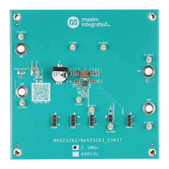
Evaluates: MAX25262/MAX25263
General Description
The MAX25262/MAX25263 evaluation kits (EV kits) come
fully assembled and tested. The EV kits demonstrate the
MAX25262/MAX25263 synchronous buck converters. The
EV kits operate over a wide 3.5V to 65V input range. The
MAX25262EVKIT is populated with the MAX25262AFOA/
VY+, and the MAX25263EVKIT is populated with the
MAX25263AFOC/VY+. The EV kit output voltage is fixed
and easily configured with minimum component changes.
Other converters in the family can be tested on the same
EV kit; however, changing the IC or the output voltage
may also require changing other components. Consult
the IC data sheet for guidance on selecting the proper ICs
and external components. Output voltage quality can be
monitored by observing the PGOOD signal.
Benefits and Features
● Input Supply Range from 3.5V to 65V
● Output Voltage: 3.3V/5V Fixed and Adjustable
from 1V to 20V
● 2A/3A Output-Current Capability
● Frequency - Synchronization Input
● Spread Spectrum Available
● Voltage Monitoring PGOOD Output Available
● Proven PCB Layout
● Fully Assembled and Tested
Ordering Information
appears at end of data sheet.
©
2021 Analog Devices, Inc. All rights reserved. Trademarks and registered trademarks are the property of their respective owners.
One Analog Way, Wilmington, MA 01887 U.S.A.
Click
here
to ask an associate for production status of specific part numbers.
Quick Start
Required Equipment
● MAX25262EVKIT/MAX25263EVKIT
● 65V, 3A power supply
● Appropriate resistive load, or an electronic load that
can sink 3A
● Digital multimeter (DMM)
● Oscilloscope
Procedure
The EV kit is fully assembled and tested. Follow the steps
below to verify board operation:
1) Verify that all jumpers are in their default positions, as
shown in
2) Connect the positive and negative terminals of the
power supply to the SUP and GND1 test pads, re-
spectively.
3) Set the power supply voltage to 24V and current limit
to 3A.
4) Turn on the power supply.
5) Using the DMM, verify that OUT is as requested.
6) Verify that the switching frequency is 2.1MHz/400kHz
(approximately) by monitoring the inductor switching
voltage with the oscilloscope.
7) Connect the positive and negative terminals of the
electronic load to OUT and GND, respectively.
8) Set the electronic load to the desired current at or
below 3A, or use an equivalent resistive load with an
appropriate power rating.
9) Adjust current limit on the power supply as necessary.
10) Turn on the power supply and electronic load.
11) Verify that voltage across the V
requested.
|
Tel: 781.329.4700
|
MAX25262/MAX25263
Evaluation Kit
Table
1.
OUT
319-100605; Rev 1; 12/21
© 2021 Analog Devices, Inc. All rights reserved.
and GND is as
Advertisement

Subscribe to Our Youtube Channel
Related Manuals for Analog Devices MAX25262


Summary of Contents for Analog Devices MAX25262
- Page 1 319-100605; Rev 1; 12/21 © 2021 Analog Devices, Inc. All rights reserved. Trademarks and registered trademarks are the property of their respective owners. One Analog Way, Wilmington, MA 01887 U.S.A. Tel: 781.329.4700 © 2021 Analog Devices, Inc. All rights reserved.
-
Page 2: Ordering Information
Detailed Description of Hardware Spread Spectrum Option The spread spectrum is pin selectable using the SPS pin. The MAX25262 and MAX25263 EV kits provide a Pull the pin high to enable spread spectrum. When spread proven layout for the MAX25262 and MAX25263 synchro- spectrum is enabled, the operating frequency is varied nous buck regulator ICs, respectively. - Page 3 MAX25262/MAX25263 Evaluates: MAX25262/MAX25263 Evaluation Kit MAX25262/MAX25263 EV Kit Bill of Materials REF DES MFG PART # MANUFACTURER VALUE DESCRIPTION RESISTOR; 0603; 20KΩ; 5%; CRCW060320K0JN VISHAY DALE 200PPM; 0.10W; METAL FILM RES; SMT (0603);0;1%; R2, R3 MC0603SAF0000T5E MULTICOMP ±400PPM/DEGC;0.1W R4, R5, R6 RES 0603 INDUCTOR;...
- Page 4 MAX25262/MAX25263 Evaluates: MAX25262/MAX25263 Evaluation Kit MAX25262/MAX25263 EV Kit Bill of Materials (continued) MAX25262EVKIT# Variant (2.1MHz, 5V) REF DES MFG PART # MANUFACTURER VALUE DESCRIPTION MAX25262AFOA/VY+ Analog Devices Buck converter IC XAL5030-332ME Coilcraft 3.3µH C13, C14, C16, C18 CGA4J1X7S1E106K125AC 10µF CAP CER 10µF 25V X7S 0805...
- Page 5 MAX25262/MAX25263 Evaluates: MAX25262/MAX25263 Evaluation Kit MAX25262/MAX25263 EV Kit Schematic Diagram See the BOM for precise component values. Analog Devices │ 5 www.analog.com...
- Page 6 Evaluation Kit MAX25262/MAX25263 EV Kit PCB Layout Diagrams 1” 1” MAX25262/MAX25263 EV Kit PCB Layout — Top Silkscreen MAX25262/MAX25263 EV Kit PCB Layout — Top Layer 1” MAX25262/MAX25263 EV Kit PCB Layout — Internal Layer 2 Analog Devices │ 6 www.analog.com...
- Page 7 Evaluation Kit MAX25262/MAX25263 EV Kit PCB Layout Diagrams (continued) 1” 1” MAX25262/MAX25263 EV Kit PCB Layout — Internal Layer 3 MAX25262/MAX25263 EV Kit PCB Layout — Bottom Layer 1” MAX25262/MAX25263 EV Kit PCB Layout — Bottom Silkscreen Analog Devices │ 7...
-
Page 8: Revision History
Information furnished by Analog Devices is believed to be accurate and reliable. However, no responsibility is assumed by Analog Devices for its use, nor for any infringements of patents or other rights of third parties that may result from its use.Specifications subject to change without notice. No license is granted by implication or otherwise under any patent or patent rights of Analog Devices.
Need help?
Do you have a question about the MAX25262 and is the answer not in the manual?
Questions and answers