Table of Contents
Advertisement
Quick Links
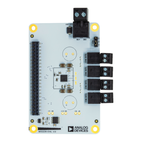
Evaluation Board for Quad Smart Serial-Controlled Driver
MAX22216-EVAL Evaluation Board
319-101029, Rev 1: 03/24
The MAX22216-EVAL allows evaluation of the MAX22216 in combination with the TRINAMIC eval-
uation board system or as stand-alone-board. It uses the standard schematic and offers several
options to test different modes of operation. The MAX22216-EVAL can also be used in the evalua-
tion of the MAX22217 by setting SNSF[1:0] = "10" for all channels while in use.
DO NOT CONNECT/DISCONNECT LOAD WHILE POWER IS CONNECTED.
WARNING
Applications
• Solenoid Valves and Relays
• Real-Time Current
Measurement
Simplified Block Diagram
©2024 TRINAMIC Motion Control GmbH & Co. KG, Hamburg, Germany
Terms of delivery and rights to technical change reserved.
Download newest version at www.analog.com.
Read entire documentation.
• Proportional Valves
• DC Motors
EVALUATION BOARD
Features
• Quad smart serial-controlled 36V half
bridges up to 1.7A/3.2A full scale
• Supply voltage 4.5V to 36V DC
• SPI and OTP registers
• Highly flexible control methods
(e.g. Bridge-Tied Load)
• Two-level current/voltage sequencer
• Detection of plunger movement
• Power-saving features
• Advanced diagnostics
• Full set of protections
• Digital-Output Interface
• Bi-stable Latching
Solenoid Valves
Advertisement
Table of Contents

Related Manuals for Analog Devices MAX22216-EVAL


Summary of Contents for Analog Devices MAX22216-EVAL
- Page 1 It uses the standard schematic and offers several options to test different modes of operation. The MAX22216-EVAL can also be used in the evalua- tion of the MAX22217 by setting SNSF[1:0] = "10" for all channels while in use.
-
Page 2: Table Of Contents
MAX22216-EVAL Evaluation Board • 319-101029, Rev 1: 03/24 2/17 Contents 1 Order Codes 2 Getting Started First Start-Up .......... - Page 3 MAX22216-EVAL Evaluation Board • 319-101029, Rev 1: 03/24 3/17 2 Getting Started Required Equipment Precautions • MAX22216-EVAL evaluation board • Do not mix up connections or short-circuit pins. • Landungsbruecke with latest firmware • Avoid bundling I/O wires with load wires.
- Page 4 1. Make sure that the latest version of the TMCL-IDE is installed. TMCL-IDE can be downloaded from www.analog.com TMCL-IDE. 2. Open TMCL-IDE and connect the Landungsbruecke with the attached MAX22216-EVAL by USB to the computer. For Windows® 8 and higher, no driver is needed. For Windows 7, TMCL-IDE installs the driver automatically.
- Page 5 MAX22216-EVAL Evaluation Board • 319-101029, Rev 1: 03/24 5/17 3 Hardware Information All design files for TRINAMIC evaluation boards are available for free. The original ECAD files, Gerber data, the BOM, and PDF copies are available. Typically, the ECAD files are in KiCAD format. Some (older) evalu- ation boards may only be available in Eagle, Altium, or PADS format.
- Page 6 NOTE voltage regulator. In the rare case of the OTP output voltage being used, neither selection should be present. This happens when the MAX22216-EVAL is started after the V output has been configured by the OTP setting. Figure 6: +VCC_IO Selection Near the EEPROM...
- Page 7 7/17 3.3 Onboard Connectors The MAX22216-EVAL has seven onboard connectors. The following table contains information on the con- nector type and mating connectors. The connector pinning and signal names can be derived from the board design and schematic files avail-...
- Page 8 MAX22216-EVAL Evaluation Board • 319-101029, Rev 1: 03/24 8/17 3.3.1 Landungsbruecke Connector All signals are connected to the MAX22216 directly without any additional protec- NOTE tion. Refer to the MAX22216 data sheet for electrical ratings. Figure 7: Pin Assignment on Landungsbruecke Connector...
- Page 9 MAX22216-EVAL Evaluation Board • 319-101029, Rev 1: 03/24 9/17 3.3.2 Load Connector The MAX22216-EVAL consists of four plugs to attach loads (see Figure 5). Each of the four plugs has one COM and one OUT_ connection. All COM pins are connected to the selection jumper (see the...
-
Page 10: Tmcl-Ide Evaluation Features
Figure 8: Configuring MAX22216 General Settings To get the MAX22216-EVAL started, set the part to ACTIVE, clear the flags within the EvalBoard Flags Tool, and select the desired output configuration through CHS. For a more stable SPI communication, CRC can be enabled. -
Page 11: Chipclick
4.2 ChipClick To configure the control pins for the MAX22216-EVAL, open the Chip Click tool by clicking the appropriate entry in the tool tree. By hovering the mouse over a pin in the graphical view, a description of the pin’s possible configurations is shown. -
Page 12: Solenoid Sequencer
Figure 10: Sequencer Configuration of One MAX22216 Channel 4.4 Solenoid Inductance To measure a specific channel of the MAX22216-EVAL, open the Solenoid Inductance by clicking the appro- priate entry in the tool tree. This tool shows the required settings for dithering or inductance/resistance measurement. -
Page 13: Bemf/Dpm Tuning
13/17 4.5 BEMF/DPM Tuning To tune a specific channel of the MAX22216-EVAL, open the BEMF/DPM Tuning tool by clicking the appro- priate entry in the tool tree. A prerequirement for this tool is a working actuation within the Solenoid Se- quencer. -
Page 14: Rapid Fire Tool
MAX22216-EVAL Evaluation Board • 319-101029, Rev 1: 03/24 14/17 4.6 Rapid Fire Tool To turn on or off a specific channel repetitvely, open the Rapid Fire tool by clicking the appropriate entry in the tool tree. This tool controls the on and off time for the selected channel. The Rapid Fire tool requires... -
Page 15: Parameter And Register Scope
15/17 4.8 Parameter and Register Scope The MAX22216-EVAL is capable of using the Parameter & Register Scope. To collect the data, the Lan- dungsbruecke buffers the desired values in real time to send them through the slower USB connection to the connected IDE. Depending on the selected sample count and number of measurement channels, this process can take some time. -
Page 16: Otp Programming
16/17 4.9 OTP Programming To configure the one-time programmable (OTP) registers for the MAX22216-EVAL, open the OTP Program- mer tool by clicking the appropriate entry in the tool tree. By pressing Refresh, currently set registers within the Registry Browser can be applied to this tool. There is a short waiting period while the register values are loaded. -
Page 17: Document Revision
MAX22216-EVAL Evaluation Board • 319-101029, Rev 1: 03/24 17/17 5 Revision History 5.1 Document Revision Version Date Description Rev 0 10/23 Initial release Rev 1 03/24 Added MAX22217 support explanation Table 4: Document Revision...
Need help?
Do you have a question about the MAX22216-EVAL and is the answer not in the manual?
Questions and answers