Advertisement
Evaluates: MAX25561, MAX25560
General Description
The MAX25561 evaluation kit (EV kit) demonstrates the
MAX25561 and MAX25560 integrated 6-channel high-
brightness LED drivers with boost controller and I
interface for automotive displays supporting ASIL B
(MAX25561 only).
The EV kit operates from a DC supply voltage between 7V
(4.5V if the LED current per string is set to 150mA or less)
and 36V, and the switching frequency can be either set at
2.2MHz or at 400kHz. The EV kit can only be configured
2
to operate in I
C mode. Spread-spectrum mode (SSM) is
enabled by default for EMI improvement, but it can be
disabled by acting on a register bit. The EV kit
demonstrates
phase-shifted,
(PWM) dimming. Dimming can be performed either
externally using a PWM signal applied to the DIM PCB pad
or internally by programming the desired dimming
frequency and individual duty cycle through I
dimming signal is applied through the DIM PCB pad,
readback of measured dimming duty cycle and frequency
will be made available on dedicated I
The hybrid dimming feature can also be enabled through
a register bit to reduce EMI.
The EV kit features a LED current foldback option as a
function of the temperature by means of an on-board NTC
2
sensor. I
C-programmable automatic fading functionality
is also available.
Finally, the EV kit demonstrates short-LED, open-LED,
boost output undervoltage and overvoltage, boost input
overcurrent, LED current/duty cycle mismatch, and
overtemperature-fault protection. Additional ASIL B
features like LED current measurement, boost input
current
measurement,
measurement are also demonstrated.
For operation at switching frequencies other than 2.2MHz
or 400kHz, the external components should be chosen
according to the calculations in the MAX25561 IC and
MAX25560 IC data sheets.
The EV kit provides an I
conjunction with the MAX32625PICO adapter or a third-
2
party I
C controller. Windows
interface (GUI) software is available for use with the EV kit
and can be downloaded on the
product pages (under the Evaluation Kits tab). A Windows
7 or newer Windows operating system is required to use
the EV kit software.
© 2023 Analog Devices, Inc. All rights reserved. Trademarks and registered trademarks are the property of their respective owners.
pulse-width
modulation
2
C. When the
2
C registers.
and
boost
output
2
C interface that can operate in
®
-based graphical-user
MAX25561
and
MAX25560
Features and Benefits
•
Demonstrates
MAX25560
•
7V (4.5V if LED Current per String Is Set to 150mA or
2
C
Less) to 36V Input Operating Range (up to 42V Load
Dump)
•
Powers HB LEDs (up to Six Strings) for Medium-to-
Large-Sized LCD Displays in Automotive and Display
Backlight Applications
•
400kHz to 2.2MHz Resistor-Programmable Switching
Frequency with Spread-Spectrum Option
•
Phase-Shift Dimming Option
•
Demonstrates
Thermal-Shutdown Features
•
Demonstrates Wide Dimming Ratio
•
Demonstrates Hybrid Dimming for Better EMI and
Acoustic Performance and Higher Dimming Ratio
•
Demonstrates Fade in/out for Smooth Brightness
Transition
•
Designed to Show Thermal Foldback Function
•
2
I
C Programmability
•
Dedicated GUI
•
Proven PCB and Thermal Design
•
Fully Assembled and Tested
MAX25561 EV Kit Files
MAX25561SetupV1_0_0000.exe
voltage
Ordering Information
Windows is a registered trademark of Microsoft Corporation.
MAX25561 Evaluation Kit
Robustness
of
Cycle-by-Cycle
Current-Limit
FILE
DESCRIPTION
Installs EV kit files onto
computer
appears at end of data sheet.
319-101042; Rev 1; 2/24
MAX25561
and
and
Advertisement
Table of Contents

Related Manuals for Analog Devices MAX25561


Summary of Contents for Analog Devices MAX25561
- Page 1 (under the Evaluation Kits tab). A Windows 7 or newer Windows operating system is required to use the EV kit software. 319-101042; Rev 1; 2/24 © 2023 Analog Devices, Inc. All rights reserved. Trademarks and registered trademarks are the property of their respective owners.
-
Page 2: Quick Start
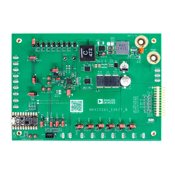
C bus for available target addresses on the bus and selects the Install the EV kit software (GUI) on your PC by running first one (in this case, the MAX25561 I C address). the MAX25561SetupV1_0_0000.exe program. The Press OK once the MAX25561 I... - Page 3 Evaluates: MAX25561, MAX25560 MAX25561 Evaluation Kit MAX25561 EV Kit Photo www.analog.com Analog Devices | 3...
- Page 4 Detailed Description of Hardware The MAX25561 EV kit demonstrates the MAX25561 and the MAX25560 HB LED drivers with an integrated step-up DC- DC preregulator followed by six linear current sinks to drive up to six strings of LEDs. The preregulator switches at 2.2MHz (or at 400kHz) and operates as a current-mode-controlled regulator, providing up to 1.35A for the linear current sinks as...
-
Page 5: Switching Frequency
Switching Frequency Jumper J18 is used to set the switching frequency of the MAX25561 to either 2.2MHz or 400kHz. When J18 is closed, the switching frequency is set to 2.2MHz. When J18 is open, the switching frequency is nominally 400kHz. See Table 4 for jumper settings. - Page 6 V18, and its function will be disabled. Only one of the above listed jumpers at a time must be closed. Table 5 for jumper settings. Refer to the LED Current Control section in the MAX25561 IC and MAX25560 IC data sheets for more information. Table 5. LED Current Initial Setting through ISET Resistor (J2 and J7-J14) ISET RESISTOR VALUE...
-
Page 7: Channel Operation
Note: By checking TON Master, it is possible to set the same on time for all the channels. For additional information on the device’s digital dimming feature, refer to the Dimming section in the MAX25561 IC and MAX25560 IC data sheets. - Page 8 HDIM Thres dropdown menu). To enable the hybrid dimming feature, check Hybrid Dimming Enable. For additional information on the device’s dimming feature, refer to the Hybrid Dimming section in the MAX25561 IC and MAX25560 IC data sheets.
-
Page 9: Ordering Information
R45 is 1kΩ, VOUT_OVP is the overvoltage-protection threshold desired, and R44 is the new resistor value for obtaining the desired overvoltage protection. Refer to the Open-LED Management and Overvoltage Protection section in the MAX25561 IC and MAX25560 IC data sheets for additional information. - Page 10 Evaluates: MAX25561, MAX25560 MAX25561 Evaluation Kit C1608X7R1H223K080AA; GCJ188R71H223KA01 C6, C52 — C0603C100K1GAC CAP; SMT (0603); 10PF; 10%; 100V; C0G; CERAMIC — C0603H101J5GAC CAP; SMT (0603); 100PF; 5%; 50V; C0G; CERAMIC C9, C15, C19, C35, — CC0603KRX7R0BB104; CAP; SMT (0603); 0.1UF; 10%; 100V; X7R; CERAMIC C38, C53, C68 GRM188R72A104KA35;...
- Page 11 Evaluates: MAX25561, MAX25560 MAX25561 Evaluation Kit JMP2-JMP7 — 22-28-4043 CONNECTOR; MALE; THROUGH HOLE; FLAT VERTICAL BREAKAWAY; STRAIGHT; 4PINS — SRP1238A-R60M INDUCTOR; SMT; SHIELDED; 0.6UH; 20%; 29A — XAL1510-472ME INDUCTOR; SMT; COMPOSITE; 4.7UH; 20%; 29A — BSS84 ENHANCEMENT MODE FIELD EFFECT TRANSISTOR, P-CHANNEL, SOT-23, PD=0.36W,...
- Page 12 Evaluates: MAX25561, MAX25560 MAX25561 Evaluation Kit — CRCW06034K30FK RES; SMT (0603); 4.3K; 1%; +/-100PPM/DEGK; 0.1000W — CRCW06031K80FK RES; SMT (0603); 1.8K; 1%; +/-100PPM/DEGC; 0.1000W — ERJ-3RQF4R7 RES; SMT (0603); 4.7; 1%; +/-100PPM/DEGC; 0.1000W — CRCW060310R0FK; RES; SMT (0603); 10; 1%; +/-100PPM/DEGC;...
- Page 13 Evaluates: MAX25561, MAX25560 MAX25561 Evaluation Kit C23, C24 GRM32ER71H106KA12; CAP; SMT (1210); 10UF; 10%; 50V; X7R; CERAMIC CL32B106KBJNNN; UMJ325KB7106KMH; 12105C106K4Z2A C26-C30, C32, GRM1885C1H102FA01 CAP; SMT (0603); 1000PF; 1%; 50V; C0G; CERAMIC C33, C75, C77, C79, C81, C83 C31, C76, C78, GRM1885C1H102JA01;...
- Page 14 Evaluates: MAX25561, MAX25560 MAX25561 Evaluation Kit MAX25561 EV Kit Schematics www.analog.com Analog Devices | 14...
- Page 15 Evaluates: MAX25561, MAX25560 MAX25561 Evaluation Kit MAX25561 EV Kit Schematics (continued) www.analog.com Analog Devices | 15...
- Page 16 Evaluates: MAX25561, MAX25560 MAX25561 Evaluation Kit MAX25561 EV Kit Schematics (continued) www.analog.com Analog Devices | 16...
- Page 17 MAX25561 Evaluation Kit MAX25561 EV Kit PCB Layouts MAX25561 EV Kit Component Placement Guide—Top MAX25561 EV Kit PCB Layout—Top Layer Silkscreen MAX25561 EV Kit PCB Layout—Internal Layer 2 MAX25561 EV Kit PCB Layout—Internal Layer 3 www.analog.com Analog Devices | 17...
- Page 18 Evaluates: MAX25561, MAX25560 MAX25561 Evaluation Kit MAX25561 EV Kit PCB Layouts (continued) MAX25561 EV Kit PCB Layout—Bottom Layer MAX25561 EV Kit Component Placement Guide—Bottom Silkscreen www.analog.com Analog Devices | 18...
-
Page 19: Revision History
Information furnished by Analog Devices is believed to be accurate and reliable. However, no responsibility is assumed by Analog Devices for its use, nor for any infringements of patents or other rights of third parties that may result from its use. Specifications subject to change without notice. No license is granted by implication or otherwise under any patent or patent rights of Analog Devices.
Need help?
Do you have a question about the MAX25561 and is the answer not in the manual?
Questions and answers