Advertisement
Quick Links
Evaluates: MAX30001
MAX30002
General Description
The MAX30001 evaluation system (EV system) provides
a single platform to evaluate the functionality and features
of the MAX30001 with Biopotential (ECG, R-to-R, and
Pace Detection) and Bioimpedance (BioZ) measurement
capabilities. The EV system includes a MAX30001 evaluation
kit (EV kit) and a MAX32630FTHR Cortex-M4F
microcontroller for wearables. The MAX32630FTHR
provides power to the MAX30001 EV kit and contains the
firmware necessary to use the EV kit GUI program. The
EV kit ships with jumpers installed and supply voltages set
to typical operating values. Optional connections exist which
can be shunted to make use of different functionalities.
Note that the MAX30002 is register compatible with the
MAX30001. By disabling the ECG, PACE, and R-to-R
blocks, the MAX30001 is equivalent to the MAX30002
and the EV kit evaluates the MAX30002 functionality and
performance.
This EV system is not a medical device.
Ordering Information
appears at end of data sheet.
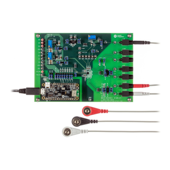
MAX30001 EV Kit Photo
Windows is a registered trademark and registered service mark of Microsoft Corporation.
One Analog Way, Wilmington, MA 01887 U.S.A.
Click
here
to ask an associate for production status of specific part numbers.
MAX30001 Evaluation System
Features
● Convenient Platform to Evaluate the MAX30001
● Many Easy-to-Reach Test Points
● Measure Individual Supply Currents
● Touchproof Cable Connectors
● Windows
● Fully Assembled and Tested
● Facilitates IEC 60601-2-47 Compliance Testing
● Ultra-Low-Power Design
EV System Contents
● MAX30001 EV kit
● MAX32630FTHR
● USB A to micro-USB cable
● Three (3) ECG cables
Note:
1.
The GUI setup files can be obtained by the Procedure
in the
2.
EVKIT design files are attached at the end of this
document.
|
Tel: 781.329.4700
|
®
7/8/10 Compatible GUI software
Quick Start
section
© 2024 Analog Devices, Inc. All rights reserved.
319-100083; Rev 2; 4/24
Advertisement

Subscribe to Our Youtube Channel
Related Manuals for Analog Devices MAX30001


Summary of Contents for Analog Devices MAX30001
- Page 1 (EV kit) and a MAX32630FTHR Cortex-M4F microcontroller for wearables. The MAX32630FTHR ● Fully Assembled and Tested provides power to the MAX30001 EV kit and contains the ● Facilitates IEC 60601-2-47 Compliance Testing firmware necessary to use the EV kit GUI program. The ●...
-
Page 2: Quick Start
MAX30001 Evaluation System Evaluates: MAX30001 MAX30002 MAX30001 Evaluation System Files FILE DECRIPTION MAX30001EVKit.exe PC GUI Program Quick Start “The publisher could not be verified. Are you sure you want to run this software?” appears, select Required Equipment the Yes option. - Page 3 MAX30001 Evaluation System Evaluates: MAX30001 MAX30002 Figure 1. The Connection Issue Dialog Box Appears If The GUI Does Not Detect the EV Kit. Figure 2. The Connection Screen Allows The User to Select Which COM Port Contains the EV Kit.
-
Page 4: Options Menu
Changing these interactive default, the maximum time is 10 seconds. controls triggers a write operation to the MAX30001 to update the register contents. Likewise, these controls are Load Register Settings allows the user to quickly set refreshed when reading from the device. - Page 5 MAX30001 Evaluation System Evaluates: MAX30001 MAX30002 Figure 4. Saving a Log File. Analog Devices │ 5 www.analog.com...
- Page 6 Start Settings description. To load a Quick Start Setting, click on the desired setting in the left box and click on Apply Settings. The MAX30001 will be written with the specified configuration. These presets allow users to quickly verify the functionality of the EV kit.
- Page 7 ADC sampling rate, are found in the ECG Channel block diagram. The R-to-R box configures R-to-R detection using the ECG input data. A detailed description of all ECG channel configuration settings and R-to-R functionality can be found in the MAX30001 data sheet.
- Page 8 ECG Bias, Resistive Bias Value set to 100MΩ, Positive Input Bias Enable and Negative Input Bias Enable set to Connected. DC Lead-Off Check, ULP Lead-On Check, and Calibration Test Voltage functionalities are detailed further in depth in the MAX30001 data sheet. Figure 7. ECG MUX Tab Analog Devices │...
- Page 9 ECG Channel tab, controls on this tab configure the filters and amplifiers of the device’s BioZ channel. A detailed description of all BioZ channel configuration settings can be found in the MAX30001 data sheet. Figure 8. BioZ Channel Tab.
- Page 10 As part of the BioZ self-test, a resistive load is available on the DRVP and DRVN pins. Clicking on Selectable Resistive Load will bring the GUI to the BioZ Load tab. Refer to the full MAX30001 data sheet for detailed descriptions of the BioZ MUX configurations.
- Page 11 MAX30001 Evaluation System Evaluates: MAX30001 MAX30002 BioZ Load The BioZ Load tab (Figure 10) configures the resistive load used for the self-test of the BioZ channel. The nominal resistance and modulation frequency are set by the Nominal Resistance and Frequency controls in the Modulated Resistance Built-In-Self-Test (RMOD BIST) block.
- Page 12 MAX30001 Evaluation System Evaluates: MAX30001 MAX30002 Pace Channel Tab The Pace Channel tab (Figure 11) configures the input channel for pace detection. In addition to setting the channel gain and detection thresholds, this tab can route signals at various points in the input path to AOUT using the Signal Selection control.
- Page 13 MAX30001 Evaluation System Evaluates: MAX30001 MAX30002 Plots Tab The Plots tab (Figure 12) enables real time monitoring of ECG and BioZ waveforms. By default, both ECG and BioZ plots are visible. Toggling the controls in Channel/Plot Enable changes which of the two plots is displayed. If ECG is enabled and BioZ is disabled, the plot area will be occupied entirely by the ECG waveform.
- Page 14 MAX30001 Evaluation System Evaluates: MAX30001 MAX30002 R-to-R and Pace data is shown in the ECG plot. R-to-R peak detection is indicated by a red circle at the peaks of the R waves. Pace data appears as teal arrows on the rising and falling slopes of the pace signal. Heart rate information gathered from R-to-R detection can be found in the Heart Rate (from R-to-R) box below the plotting area.
- Page 15 Erase buttons, respectively. Pressing Advanced displays the current register contents to be written to an SD card The MAX30001 EV kit can use the SD card read/write setting file when Write is pressed. After confirming the functionality of the MAX32630FTHR to store and recall register configurations, select the type of data to save in log data to and from a microSD card.
- Page 16 The Registers tab (Figure 15) provides more direct access to the internal registers of the MAX30001. From this tab, it is possible to read the contents of individual registers and to manually enter the desired bit settings for a write operation.
- Page 17 16) is accessible through the Options ToolStrip menu. The tab provides manual communication with the MAX30001 to bypass the GUI controls entirely. Enter the register address, as a hexadecimal value, in the Address field. Read data from a register by pressing the ReadReg button and the data will populate the Read Data field. To write data, enter the hexadecimal value in the Write Data field and press the WriteReg button.
- Page 18 GUI. When the to test the MAX30001 under several conditions. A list of EV kit operates without a host PC, pressing SW2 on the all jumpers and their respective functions is available in...
- Page 19 MAX30001 Evaluation System Evaluates: MAX30001 MAX30002 Table 1. Description Of Jumpers (continued) JUMPER SHUNT POSITION DESCRIPTION Supply 1.8V to J_AVDD and J_DVDD from the MAX32630FTHR. 2-3* Supply an adjustable voltage to J_AVDD and J_DVDD from an LDO (U2). Supply 3.3V to J_OVDD and OVDDX from the MAX32630FTHR.
- Page 20 MAX30001 Evaluation System Evaluates: MAX30001 MAX30002 MAX32630FTHR INTB INT2B AVDD DVDD OVDD J_AVDD INTB INT2B AVDD J_DVDD DVDD OVDD J_OVDD EP_UNBAL 0Ω J_ECGP ECGP ECGP EP_EN 0Ω J_ECGN ECGN ECGN EN_UNBAL 0Ω J_BIP MAX30001 BP_BN 100Ω 0Ω J_BIN 47nF J_DRVP...
- Page 21 MAX30002 Powering the EV Kit Configuring the Board for Measurement The MAX30001 EV kit can be powered from an external The MAX30001 EV kit offers several potential connection supply or directly from the MAX32630FTHR. To use an and component configurations to enable a variety of tests.
- Page 22 Figure 19 illustrates these connections. configuration to measure ECG with pace detection. Refer to the MAX30001 data sheet for details on configuring Alternatively, EP_BP and EN_BN can be left open and a BioZ measurement. Note that the default setting of the J_BIP and J_BIN shunted.
- Page 23 MAX30001 Evaluation System Evaluates: MAX30001 MAX30002 EP_UNBAL 0Ω J_ECGP ECGP ECGP EP_EN J_ECGN 0Ω ECGN ECGN EN_UNBAL EP_BP EN_BN J_BIP 0Ω BP_BN 100Ω J_BIN 0Ω DP_BP DN_BN 47nF J_DRVP DRVP DRVP 47nF J_DRVN DRVN DRVN Figure 19. BioZ Measurement with 100Ω Test Impedance.
-
Page 24: Ordering Information
Susuma www.susuma-usa.com Taiyo Yuden www.t-yuden.com www.global.tdk.com TE Connectivity www.te.com Vishay Dale www.vishay.com Note: Indicate that you are using the MAX30001 EV kit when contacting these component suppliers. Ordering Information PART TYPE MAX30001EVSYS# EV System Analog Devices │ 24 www.analog.com... - Page 25 MAX30001 Evaluation System Evaluates: MAX30001 MAX30002 MAX30001 EV Kit Bill of Materials (BOM) ITEM REF_DES DNI/DNP MFG PART # MANUFACTURER VALUE DESCRIPTION 1V8, 3V3, GND1, GND2, J_CSB, CONNECTOR; MALE; THROUGH HOLE; BREAKAWAY; J_SDI, J_SDO, J_SYS, BB_SEL, PCC03SAAN SULLINS PCC03SAAN STRAIGHT THROUGH; 3PINS; -65 DEGC TO +125 DEGC...
- Page 26 MAX30001 Evaluation System Evaluates: MAX30001 MAX30002 MAX30001 EV Kit Schematic Analog Devices │ 26 www.analog.com...
- Page 27 MAX30001 Evaluation System Evaluates: MAX30001 MAX30002 MAX30001 EV Kit Schematic (continued) Analog Devices │ 27 www.analog.com...
- Page 28 MAX30001 Evaluation System Evaluates: MAX30001 MAX30002 MAX30001 EV Kit PCB Layout Diagrams 1.0’’ MAX30001 EV Kit—Top Silkscreen Analog Devices │ 28 www.analog.com...
- Page 29 MAX30001 Evaluation System Evaluates: MAX30001 MAX30002 MAX30001 EV Kit PCB Layout Diagrams (continued) 1.0’’ MAX30001 EV Kit—Top Analog Devices │ 29 www.analog.com...
- Page 30 MAX30001 Evaluation System Evaluates: MAX30001 MAX30002 MAX30001 EV Kit PCB Layout Diagrams (continued) 1.0’’ MAX30001 EV Kit—Layer 2 Analog Devices │ 30 www.analog.com...
- Page 31 MAX30001 Evaluation System Evaluates: MAX30001 MAX30002 MAX30001 EV Kit PCB Layout Diagrams (continued) 1.0’’ MAX30001 EV Kit—Layer 3 Analog Devices │ 31 www.analog.com...
- Page 32 MAX30001 Evaluation System Evaluates: MAX30001 MAX30002 MAX30001 EV Kit PCB Layout Diagrams (continued) 1.0’’ MAX30001 EV Kit—Bottom Analog Devices │ 32 www.analog.com...
- Page 33 MAX30001 Evaluation System Evaluates: MAX30001 MAX30002 MAX30001 EV Kit PCB Layout Diagrams (continued) 1.0’’ MAX30001 EV Kit—Bottom Silkscreen Analog Devices │ 33 www.analog.com...
-
Page 34: Revision History
Information furnished by Analog Devices is believed to be accurate and reliable. However, no responsibility is assumed by Analog Devices for its use, nor for any infringements of patents or other rights of third parties that may result from its use.Specifications subject to change without notice. No license is granted by implication or otherwise under any patent or patent rights of Analog Devices.
Need help?
Do you have a question about the MAX30001 and is the answer not in the manual?
Questions and answers