
Related Manuals for Intec ColorSplash CS4000


Summary of Contents for Intec ColorSplash CS4000
- Page 1 Intec ColorSplash CS4000 and CS5000 Enhanced Print Production Envelope Feeder Installation and Set Up Guide Version 2 NOV 2015...
-
Page 2: Table Of Contents
1.1. ColorSplash EPP Envelope Feeder Components 1.2. Control Panel Components and Features 2. InStallatIon GUIdE 2.1. Preparing the INTEC CS4000 / CS5000 Printer for use with your Intec EPP Envelope Feeder 2.1.1. Removing the MPT Tray/Door 2.1.2. Removing the Outer Separation Pad 2.1.3. -
Page 3: Getting Started
1. GEttInG StartEd 1.1. ColorSplash EPP Envelope Feeder Components Back Wedge assembly Paper guide assembly Bridge Feed belts Paper guide hopper adjustment knob Acceleration table Buckle separator assembly paper guide Envelope hold Acceleration table down strap paper guide Optical sensor Acceleration table (RESTART envelopes) Optical sensor (STOP envelopes) -
Page 4: Control Panel Components And Features
1.2. Control Panel Components and Features Timeout reset / Jog button* Mains power switch Speed adjust knob 24 Vdc power input jack Ready/Feed switch Fuse holder (5 amp fuse) *tIMEoUt FEatUrE The colorSplash’s EPP Envelope Feeder The variable speed control can be features a timeout function. -
Page 5: Installation Guide
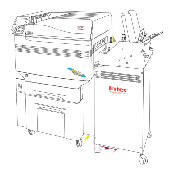
2. InStallatIon GUIdE The Intec colorSplash’s EPP Envelope Feeder is designed to operate with the new Intec colorSplash digital production printers. This guide will show the proper way to prepare the printer for the envelope feeder and installation and operation of the feeder. -
Page 6: Removing The Outer Separation Pad
2.1.2. removing the outer Separation Pad Step 5. Open the right side cover on the printer by pulling on the latch shown here: Step 6. With the right side door fully open, lift the feed roller assembly to gain access to the feed roller and sheet separator area. -
Page 7: Assembly Of The Intec Colorsplash Envelope Feeder
2.2. assembly of the Intec ColorSplash Envelope Feeder Step 1. After removing the feeder from the shipping container, carefully place the feeder and cabinet in the upright position. Step 2. Open the door on the rear of the cabinet and remove the accessories box. -
Page 8: Assembly Of Top Plate
2.2.1. assembly of top Plate Step 4. Using the included 1/8" Allen wrench, remove the four button head screws from the top of the back plate of the feeder. Step 5. Attach the top plate to the feeder using the four button head screws removed in Step 4. -
Page 9: Fitting The Paper Hold Down Strap
2.2.3. Fitting the Paper hold down Strap Step 11. Remove the shoulder screw from the paper hold down strap pivot block. Pivot block for paper hold down strap Shoulder screw Step 12. Place the end of the hold down strap (opposite pivot block end) underneath the acceleration table cross bar and on top of the transport belt. -
Page 10: Positioning The Envelope Buckle Separator
2.2.4. Positioning the Envelope Buckle Separator Step 15. Loosen the locking knob holding the envelope buckle separator in position on the bridge. Step 16. Slide the buckle separator to the center of the feeder and position the yellow tip at the bottom between the two center feed belts as shown in the photo. -
Page 11: Operating Guide
3. oPEratInG GUIdE IMPortant: It is recommended that you set up the feeder for your envelopes before moving the feeder into position with the printer. This will ensure complete access to the paper guides on the acceleration table and make testing the feeder easy. The colorSplash’s EPP Envelope Feeder can feed a variety of envelope sizes and types into the printer via the printer’s manual feed tray. - Page 12 Step 3. Loosen the locking knobs on the acceleration table paper guide blocks and slide the acceleration table paper guides outward. Grasp the paper guide block to move the guides. Locking knobs Step 4. Loosen the back wedge assembly locking knob and slide the back wedge back away from the feed belts for easy access to the envelope hopper area.
-
Page 13: Setting The Envelope (Buckle) Separator(S)
3.2. Setting the Envelope (Buckle) Separators(s) The colorSplash EPP Envelope Feeder utilizes a patented technique for separating the bottom envelope from the stack called 'buckle separation'. This unique method separates the envelopes by buckling them downward between feed belts. This results in simple sheet separation and minimizes envelope scuffing and paper jams. You will notice in the following instructions that the separator(s) are positioned between the feed belts, not over them. - Page 14 3.2 Setting the Envelope Separator(s) (continued) Step 1. If using a single separator (recommended), ensure that the buckle separator is positioned in the gap between the two center feed belts. Step 2. Rotate the separator height adjustment knob clockwise several turns to raise the separator tip up above the level of the feed belts.
- Page 15 Step 5. continue to slowly lower the separator tip until the envelope is buckled downward between the belts slightly (approx 2mm (1/16") to 3mm (1/8"). Lower the separator tip to 'buckle' the envelope down between belts NOTE: Ensure that the separator tip is between feed belts so it does not 'pinch' the envelope. Step 6.
-
Page 16: Setting Up The Back Wedge
3.3. Setting up the Back Wedge The back wedge, attached to the rear plate of the feed hopper is a very important tool that must be set properly to obtain the best results. 3.3.1. Purpose of the Back Wedge The back wedge performs several important functions: 1. - Page 17 Step 4. With one hand, raise the back end of the envelope stack up and then slide the back wedge into position underneath the back end of the stack. Lock the wedge in place with the locking knob. as shown in the pictures above and left, the back wedge should be in just far enough to hold the back edge of the envelope stack up off the belts.
-
Page 18: Setting The Back Wedge For Large Envelopes
3.3.3. Setting the Back Wedge for large envelopes In addition to setting the paper guides properly for large envelopes, the back wedge will need to be adjusted. For larger (longer) envelopes, you will need to move the back wedge further away from the bridge. Back wedge locking knob Larger (longer) envelopes have a tendency to 'sag' downward in the middle, which can cause double feeding or inconsistent gaps between envelopes. -
Page 19: Setting The Acceleration Table Paper Guides
3.4. Setting the acceleration table Paper Guides The patented 'floating' or tilting delivery table on the colorSplash EPP envelope feeder is designed to advance the envelopes that the feed belts deliver, one at a time, into the printer’s manual feed tray feed roller. The acceleration table is equipped with self centering paper guides, an envelope drive belt and a stop photo sensor at the end. - Page 20 Step 3. Set the speed control knob on the control panel to approximately 20% to test the feeder. Step 4. With the green feed switch in the off position, turn on the feeder power with the red power switch. Step 5. Move the green feed switch to the 'resume feeding' position to start the feeder.
-
Page 21: Checking Your Feeder Setup
4. ChECkInG yoUr FEEdEr SEtUP Step 1. Pull the first envelope out of the end of the acceleration table. The feeder should advance the next envelope into position over the stop photo sensor. Repeat this procedure to ensure that the feeder is functioning properly. -
Page 22: Daily Operation (Running Envelopes With Your Printer)
5. daIly oPEratIon (running envelopes with your printer) 5.1. Mounting/Connecting your Envelope Feeder Step 1. Prepare the printer to work with the envelope feeder as described in the first section of this manual. Step 2. Set the feeder and acceleration table for your envelopes and ensure consistent feeding away from the printer as described in the previous section. -
Page 23: Envelope Feeder's Latch Mechanism
Step 7. When the end of the acceleration table is 25-50mm (several inches) into the manual feed tray, let the acceleration table down to rest on the manual feed tray. continue to push the feeder in towards the printer ensuring that the ends of the dark gray side plates enter the manual feed tray opening. -
Page 24: Setting The Feeder's Speed Control
5.3. Setting the Feeder’s speed control Step 9. Set the speed control on the feeder to approximately 50 to 60% of maximum if you are running standard size envelopes. For larger envelopes, set the speed control to approximately 80 to 100%. 5.4. -
Page 25: Paper Jam Or Feeder Out Condition
IMPORTANT NOTES: The printer will only recognize that the feeder is ready if the envelopes have been advanced down the acceleration table (Stopping at the STOP Optical Sensor) AND the “Feeder Ready” lever has been pushed forward. If you want to pause printing, simply move the 'Feeder Ready Lever' back (right) and the printer will consider this an envelope out condition, similar to taking paper out of the paper tray. -
Page 26: Setting The Intec Colorsplash Envelope Feeder's Speed Control
5.6. Setting the Intec ColorSplash Envelope Feeder’s Speed Control Testing of various sized envelopes has resulted in the following suggestions for speed settings : EU – DL envelopes / US - #10 envelopes, (landscape orientation) - 50% to 60 % speed EU –... -
Page 27: Troubleshooting
6. troUBlEShootInG 6.1. note on new ColorSplash printers The new generation of these printers offers high speeds, excellent print quality and the ability to print envelopes well. Setting the colorSplash’s EPP Envelope Feeder properly to achieve consistent envelope delivery to the printer is imperative as the printer does not 'retry' in the manual feed tray. - Page 28 © 2015 Intec Printing Solutions. Intec brand names and products are the intellectual property and copyright of Intec Printing Solutions. Equipment specifications are subject to change without prior notice. Print speed may vary depending on system configuration and software applications, driver and printer settings. This specification sheet was printed on the Intec cP3000. E&OE...
Need help?
Do you have a question about the ColorSplash CS4000 and is the answer not in the manual?
Questions and answers