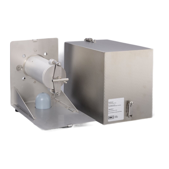
M&C SP Series Instruction Manual

M&C SP Series Instruction Manual

Gas sample probe
Hide thumbs Also See for SP Series:
Table of Contents

Advertisement

Gas Sample Probe Series SP
®
SP3200V /.../HEX5-x.08,
SP3200 /.../RS/HEX5-x.08
II 3 GD
Instruction Manual
Version 1.00.04

Advertisement

Table of Contents
loading

Summary of Contents for M&C SP Series

  • Page 1 Gas Sample Probe Series SP ® SP3200V /.../HEX5-x.08, SP3200 /.../RS/HEX5-x.08 II 3 GD Instruction Manual Version 1.00.04...
  • Page 2 Dear customer, Thank you for buying our product. In this manual you will find all necessary information about this M&C product. The information in the manual is fast and easy to find, so you can start using your M&C product right after you have read the manual. If you have any question regarding the product or the application, please don’t hesitate to contact M&C or your M&C authorized distributor.
  • Page 3: Table Of Contents

    Contents General information ........................ 5 Declaration of conformity ....................... 6 Safety information ........................7 Information for use in hazardous areas ..................8 Warranty ........................... 8 Terms and signals used in this manual ..................9 Application ..........................11 Description ..........................11 SP3200V and SP3200 (combustible gases and dust): ............
  • Page 4 Tables Table 1 Sample tube for use with probe SP3200(V) ............... 12 Table 2 Possible filters and preliminary filters for use inside the probe ........... 13 Table 3 Extension tubes ......................... 13 Table 4 Maximum surface temperatures for the use of heating HEX5-x.08 ........22 Table 5 Temperature classes for use of heating HEX5-x.08 ............
  • Page 5: General Information

    Head Office M&C TechGroup Germany GmbH  Rehhecke 79  40885 Ratingen  Germany Telephone: 02102 / 935 - 0 Fax: 02102 / 935 - 111 E - mail: info@mc-techgroup.com www.mc-techgroup.com GENERAL INFORMATION The product described in this instruction manual has been built and tested in our production facility. All M&C products are packed to be shipped safely.
  • Page 6: Declaration Of Conformity

    DECLARATION OF CONFORMITY CE - Certification The product described in this operating manual complies with the following EU directives: ATEX-Directive The product described in this manual is produced in accordance with the EU directive for devices and protection systems for appropriate use in hazardous areas 2014/34/EU appendix II. The respective type of protection depends on the variant (see table 4).
  • Page 7: Safety Information

    SAFETY INFORMATION Observe the following fundamental safety precautions when using the device: • Read these operating instructions carefully before start-up and use of the device! The information and warnings given in these operating instructions must be observed. • Work on electrical equipment may only be carried out by qualified personnel in accordance with up-to- date regulations.
  • Page 8: Information For Use In Hazardous Areas

    INFORMATION FOR USE IN HAZARDOUS AREAS Please see the identification of the individual variants in table 4. Detailed information and a copy of the declaration of conformity are contained in the ap- pendix to these operating instructions. The devices must be installed and used in accord- ance with the conditions and installation instructions given in the EX-Certificate (see ap- pendix).
  • Page 9: Terms And Signals Used In This Manual

    TERMS AND SIGNALS USED IN THIS MANUAL The ‘Danger’ warning sign indicates that death, serious injury and/or significant material damage will be the consequence, if the appropri- ate precautions should not be taken. Danger The ‘Warning’ warning sign indicates that death, serious injury or damage to property may occur if the relevant precautionary measures are not observed.
  • Page 10 Corrosive! These substances destroy living tissue and equipment upon contact. Do not breathe vapors; avoid contact with skin and eyes. Wear protective gloves! Working with chemicals, sharp objects or extremely high tempera- tures requires wearing protective gloves. Wear safety glasses! Protect your eyes while working with chemicals or sharp objects.
  • Page 11: Application

    APPLICATION The probes of type SP3200V.. and SP3200.. are used for continuous gas sampling in dust-laden processes or processes with high temperatures (according to table 5, chapter 10) or high gas moisture. The modular con- struction of the probes and the variety of possible options guarantee optimum adaptation of the probes to complex process and environmental conditions.
  • Page 12: Figure 1 Probe Sp3200(V) Without Options With Preliminary Filter V20

    After the filtration, i.e. at the outlet of the gas sample probe, the sample gas is free of dust. This means that in the absence of explosive sample gas downstream analysers can be used without any special protective measures. The following figure shows the basic version of the gas sample probe SP3200(V) with prefilter. Figure 1 Probe SP3200(V) without options with preliminary filter V20 SP3200V / SP3200:...
  • Page 13: Table 2 Possible Filters And Preliminary Filters For Use Inside The Probe

    Dimension Type Part No. Material Filter porosity[µm] [mm] Filter in the probe: 90F0126 S-3 SS150 1.4404 150 x 30 S-2K150 90S0020 Ceramic Aerolith 150 x 30 Option spun glass cartridge FW Spun glass, high tempera- Filter FW (spun glass) 93S2083 ture resistant Preliminary filters to be selected: PTFE needled felt (anti-...
  • Page 14: Options

    OPTIONS The following options are suitable for use in hazardous areas. Please read the identification for the respective zone in table 4. When selecting options, attention must be paid to the operating parameters. Warning Entnahmesonde Entnahmesonde S ample P robe S ample P robe Meßgasausgang Meßgasausgang...
  • Page 15: Backflush Unit Type /Rs

    General safety instructions for back flushing and feeding of calibration gas A backflushing gas suitable for the sampling point must be selected for backflushing. The backflushing pressure / calibration gas pressure must always be higher than the process pressure. This minimum pressure must be monitored with a press switch at the inlet side of the accumulator or the check valve.
  • Page 16: Option /C/I Test Gas Feeding Via Check Valve Behing The Probe Filter With Pneumatic Stop Valve Of The Probe Outlet To The Process

    During the feeding of test gas, the analyse system remains connected. The quantity of test gas should be at least 25 % higher than the quantity of sample gas which is taken in by the analysing system, thus avoiding a mixture with the test gas.
  • Page 17: Option /3Va Test Gas Feeding And Backflushing Via 3/2-Way Ball Valve

    OPTION /3VA TEST GAS FEEDING AND BACKFLUSHING VIA 3/2-WAY BALL VALVE With the 3/2-way ball valve, you can execute both functions „backflushing“ and „test gas feeding“ one after the other. Only one operation each may be automated via the pneumatic actuation. This kind of gas feeding provides the advantage that during backflushing the downstream analyse system is automatically separated from the probe respectively, the probe is automatically separated from the process during test gas feeding.
  • Page 18: Ball Valve Drive Ms1

    BALL VALVE DRIVE MS1 The following drives are available: Pneumatic drive with spring return type MS/ NC or NO Hereby 2 operating conditions can be realised: a. Using a shut off ball valve VA the conditions: "Open=measuring" and "shut". b. Using a 3/2-way ball valve 3VA either the conditions: "Open=measuring"...
  • Page 19: Technical Data

    10 TECHNICAL DATA Gas sample probe type SP3200V (up to 185 °C) SP3200 (more than 185 °C) Part No. 20S5705 20S5700 Weather protection shield Filter housing material Stainless steel 316/316Ti Sealing materials Graphite, FKM Graphite Probe flange sealing material Graphite Pre-filter/sample tubes Optional, see data sheet 2.17 and 2.14 Sample pressure max.
  • Page 20 Low temperature alarm contact − 5 °C to T , capacity 250 V 3 A AC, 0.25 A DC, 1 contact NO, dry contacts Excess temperature limiter +5°C to T , manual reset Option back purge unit type RS Part No. 20S5560(a) Power supply 230 V 50/60 Hz 9 W or 115 V 50/60 Hz 9 W (a)
  • Page 21 Option test gas valve / shut-off valve /C + /I Part No. 20S9011 + 20S9009 Way of test gas Via sample gas outlet with shut-off to the process Check valve Check valve 1/4” Opening pessure > 0.7 bar Connection 6 mm tube Shut-off valve Bellow-type valve with pneumatic drive Pressure control air...
  • Page 22: Maximum Surface Temperature Of The Gas Sample Probe

    10.1 MAXIMUM SURFACE TEMPERATURE OF THE GAS SAMPLE PROBE: The maximum surface temperature of the gas sample probe depends on the tem- perature of the process medium and the options used (heating HEX5-x.08 and backflush /RS). Under no circumstances, the sample probes SP3200(V)… must ex- ceed the maximum surface temperature fixed by the temperature class.
  • Page 23: Receipt Of Goods And Storage

    11 RECEIPT OF GOODS AND STORAGE • The probe and any special accessories should be unpacked carefully immediately upon delivery and checked against the delivery note for completeness. • The delivery should be checked for transport damage and the transport insurer notified immediately of any damage.
  • Page 24: Preparations For Installation

    12 PREPARATIONS FOR INSTALLATION First make sure that conditions at the intended place of use correspond to the data on the rating plate. The temperature of the process must be taken into account when selecting the sam- pling point. Heating of the probe above the temperature limit given in table 5 must be prevented. It must be ensured that the temperature class of the probe corresponds to the ignition temperatures of the combustible gases/vapours.
  • Page 25: Installation

    The prevailing operating parameters must be checked against the following table prior to installation: Operating parameters for the combustible gas (SP3200(V)) Gas composition  corrosive  toxic  explosive Zone classification process side Zone classification environment Ignition temperature of the gases/vapours °C Corresponds to tem- (>max.
  • Page 26: Figure 4 Schematic Drawing Of The Filter Housing Cover

    The following procedure is recommended: • Remove the probe cover after opening the two toggle-type fasteners. Figure 4 Schematic drawing of the filter housing cover • Turn handle A about one full turn anticlockwise so that the cover is lifted. •...
  • Page 27: Figure 5 Removal Of The Filter Housing Cover

    The following figures illustrate the steps described above. Figure 5 Removal of the filter housing cover • Check that the filter element is screwed on firmly. • Insert the filter holder part again. The filter holder part is closed in reverse order. •...
  • Page 28: Connection Of The Sample Line

    13.1 CONNECTION OF THE SAMPLE LINE • A ¼” NPT internal thread is provided on the probe side for connection of the sample line. Suitable con- necting unions for explosion-protected lines in the sizes Ø 6 mm (standard), 8 mm or 10 mm can be screwed into this thread using PTFE sealing tape.
  • Page 29 When using the option backflushing unit /RS the corresponding line must be connected to the accumulator. A backflushing gas suitable for the sampling point must be selected for backflushing. The backflushing pressure must always be higher than the process pressure. This min- imum pressure must be monitored at the inlet side of the accumulator with a pressure monitoring switch.
  • Page 30: Electrical Connection

    14 ELECTRICAL CONNECTION A wrong supply voltage can damage the device. Make sure that the supply voltage Warning corresponds to the voltage shown on the rating plate before connecting the device. The requirements of VDE 0100 and its associated standards and regulations must be observed when erecting high-voltage power installations with rated voltages of up to 1000 V! In any case, we recommend the use of heat-resistant cables.
  • Page 31: Starting-Up

    15 STARTING-UP The requirements of VDE 0100 and its associated standards and regulations must be observed when erecting high-voltage power installations with rated voltages of up to 1000 V. An external main switch must be provided. For option /RS, the control circuit of the solenoid valve must be protected with a 0.1 A fuse for 230 V/50 Hz, a 0.2 A fuse for 115 V/60 Hz or a 1 A fuse for 24 V.
  • Page 32: Replacement Of The Filter Element

    Work on the gas sample probe must only be carried out when the environment has been declared as non-hazardous area, i.e. it is free of explosive atmospheres. The process side must also be declared as non-hazardous area – free of explosive Warnung atmospheres –...
  • Page 33: Replacement Of The Preliminary Filter

    16.2 REPLACEMENT OF THE PRELIMINARY FILTER The complete probe unit must be removed from the process before replacing the preliminary filter. The pre- liminary filter can, depending on the type and degree of contamination, be cleaned mechanically or in an ul- trasonic bath and is then reusable.
  • Page 34: Spare Parts List

    19 SPARE PARTS LIST Wear, tear and replacement part requirements depend on specific operating conditions. The recommended quantities are based on experience and they are not binding. Gas sample probe SP3200 and SP3200V (C) Consumable parts (R) Recommended spare parts (S) Spare parts Recommended quantity being in operation [years]...
  • Page 35: Figure 6 Sp3200 Rs, Hex5-1.08

    Figure 6 SP3200 RS, HEX5-1.08 www.mc-techgroup.com SP3200.. | 1.00.04...
  • Page 36: Figure 7 Sp3200 Rs, Hex5-2.08

    Figure 7 SP3200 RS, HEX5-2.08 SP3200.. | 1.00.04 www.mc-techgroup.com...
  • Page 37 www.mc-techgroup.com SP3200.. | 1.00.04...
  • Page 38 SP3200.. | 1.00.04 www.mc-techgroup.com...
  • Page 39 www.mc-techgroup.com SP3200.. | 1.00.04...
  • Page 40 SP3200.. | 1.00.04 www.mc-techgroup.com...
  • Page 41 www.mc-techgroup.com SP3200.. | 1.00.04...
  • Page 42 SP3200.. | 1.00.04 www.mc-techgroup.com...

Table of Contents