
Related Manuals for M&C GenTwo PMA1000V2.4


Summary of Contents for M&C GenTwo PMA1000V2.4
- Page 1 Multigas Analyzer GenTwo® GenTwo® PMA1000 V2.4 Instruction Manual Version 1.00.00 Software Version: starting at 2.24...
- Page 2 Quick support If you have any questions about this product regarding commissioning, handling or technical service - feel free to contact us. We will support you directly, quickly and of course free of charge with our experience and product knowledge. Please contact our service center in Ratingen, Germany, for US Service Ventura, California Please help us by providing this information about the device, if...
-
Page 3: Table Of Contents
Table of Contents 1 About this instruction manual 2 Important safety information Intended use 2.2 Personal safety 2.3 Warning signs and definitions 2.4 Safety instructions 2.5 Working on electrical and electronic devices 2.6 Not certified in hazardous areas 3 Introduction 4 Product overview 5 Receiving the analyzer 5.1 Rack-housing: warning symbols and product label... - Page 4 8 Using the analyzer 8.1 Graphical user interface (GUI) 8.2 How to use the touch screen 8.3 Menu structure 8.3.1 System status line 8.3.2 Main menu bar 8.3.3 Main display area 8.3.4 Language selection 8.3.5 M1/S1 and M1/S2 - M&C contact and GUI version number 8.3.6 M1/S4 - Operating hours counter 8.3.7...
- Page 5 14 Appendix 14.1 Trouble shooting 14.2 AK protocol 14.3 Modbus protocol 14.4 Additional Information 14.5 Declaration of conformity 14.6 Certificates 14.7 Warranty 14.8 Liability and disclaimer 14.9 Storage 14.10 Shipping and handling 14.11 Proper disposal of the device 15 About us 15.1 M&C‘s group of companies 15.2 The quality-oriented M&C catalog 15.3 Technical consulting services...
-
Page 6: About This Instruction Manual
About this instruction manual Welcome to the M&C instruction manual. The goal of this document is to give a broad overview of the main functions of the GenTwo® PMA1000 V2.4. It will help you to get start- ed with using the GenTwo® analyzer. If you have any questions about this instruction manual, please contact M&C or one of our official distributors. -
Page 7: Important Safety Information
Important safety information Read this important safety information carefully before installing the GenTwo® PMA1000 V2.4. Follow these safety precautions during commissioning, start-up and regular operation. Intended use This GenTwo® PMA1000 V2.4 gas analyzer is intended for use in general purpose areas (non-hazardous environments). - Page 8 NOTICE NOTICE is used to address practices not related to physical injury. High Caution, risk of electric shock! Voltage! High Caution, system might be under pressure. Pressure! Hot Surface! Caution, hot surface! Do not touch! Hazardous Caution, hazardous and toxic gas! Do not inhale! Gas! “Qualified personnel”...
-
Page 9: Safety Instructions
2.4 Safety instructions Follow these safety directions and instructions regarding installation, commissioning and operation of the GenTwo® PMA1000 V2.4. Installation, commissioning, maintenance, inspections and any repairs Qualified of all M&C products and components must be carried out by quali- personnel fied personnel in compliance with the current regulations. -
Page 10: Working On Electrical And Electronic Devices
2.5 Working on electrical and electronic devices Only qualified and authorized personnel are permitted to work on equipment which op- erates on 115 or 230 V AC supply voltage. Observe the generally accepted engineering standards and all of your national and local regulations. Before connecting the device, please make sure that the supply Note voltage matches the specified voltage on the product label. -
Page 11: Introduction
Introduction Congratulations on your purchase of the GenTwo® PMA1000 V2.4 analyzer. We know from experience that you surely will enjoy this reliable and durable M&C product. M&C is one of the premium and performance-driven companies in the business. With this in mind, our customers benefit from a number of significant advantages. -
Page 12: Product Overview
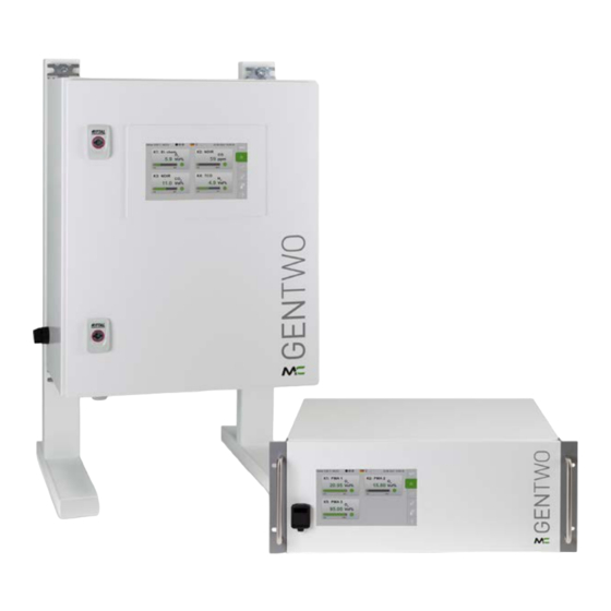
Product overview The oxygen analyzer PMA1000 V2.4, a device of the GenTwo® series, is suitable for the con- tinuous measurement of the oxygen content in gases. Directly streaming the measure- ment cell with a small gas volume of just 2 ml [≈ 0.122 in3] provides a very fast response time of the analyzer. -
Page 13: Receiving The Analyzer
Receiving the analyzer Wall-mount housing: Heavy device! Risk of injury when handling heavy equipment. CAUTION Do not lift, move or carry the device without help. A second person is required to lift, move or carry the device. The GenTwo® PMA1000 V2.4 is usually delivered in one package. You will find the following items in the box: GenTwo®... -
Page 14: Wall-Mount Housing: Warning Symbols And Product Label
5.2 Wall-mount housing: warning symbols and product label Fig. 2: Product label on the side of the wall-mount housing Product label Fig. 3: Warning symbol at the bottom of the wall-mount housing Label: max. gas pressure: Atm. Warning symbol regarding max. gas pressure at the ±200 mbar sample gas in and outlets, and regarding hazardous gases according to hazard assessment... -
Page 15: Fig. 4: Warning Symbols Inside Wall-Mount Housing
Fig. 4: Warning symbols inside wall-mount housing Warning symbol regarding high voltage at Warning symbol regarding relays switching the mains supply voltage connection high voltage under the protective cover Fig. 5: Warning symbol close to the relay connections (cover removed) Warning symbol regarding relays switching high voltage GenTwo®... -
Page 16: Measuring Principles
Measuring principles The O2 analyzer PMA1000 V2.4 of the GenTwo® series utilizes the paramagnetic dumbbell principle of operation to measure the oxygen concentration. This physical measuring principle is characterized by its accuracy, absolute linearity and low-drift, long-term stable measurement in the range of 0 to 100 vol% oxygen without consuming sensor material or auxiliary materials. -
Page 17: Fig. 7: Electronic Evaluating System To Measure Oxygen Concentration
If there is oxygen in the sample gas, it is drawn into the area between the magnetic pole pieces and tries to displace the dumbbell located there from the zero position. This is counteracted by a current through the loop wire and the resulting compensation magnet- ic field. -
Page 18: Technical Data Basic Instrument
Technical data basic instrument Multigas Analyzer GenTwo V2.4 Short enclosure with Viton® gas 08A2020 path, Part No. Long enclosure with Viton® gas 08A2025 path, Part No. Wall-mount housing with Viton® 08A2030 gas path, Part No. Short enclosure with stainless 08A2035 steel gas path, Part No. - Page 19 Multigas Analyzer GenTwo V2.4 Display 7“ capacitive color touchscreen Analog output signal 1 x 0-20 mA/4-20 mA, max. 500 Ohms burden, short-circuit proof, electrically isolated Status relay outputs 4 x relay output (1 x status, 1 x Cal. mode, 1 x pump, 1 x Cal.
-
Page 20: Dimensions 19" Rack Housing
7.1 Dimensions 19" rack housing Fig. 8: 19" rack housing front view Fig. 9: 19" rack housing side view (long housing) GenTwo® PMA1000 V2.4 | 1.00.00 www.mc-techgroup.com... -
Page 21: Dimensions Wall-Mount Housing
7.2 Dimensions wall-mount housing Fig. 10: Wall-mount housing, front and side-view 7.3 Connections 19"-rack device Fig. 11: Back view of 19" rack housing with connections (max. equipped) CAN bus connector (optionally): contact 1: CAN Ethernet connector High, contact 2: CAN Low, contact 3: not assigned Power supply plug with power switch mA-output (measurement value) with 2-pin connectors per channel... -
Page 22: Fig. 12: Bottom-View Of Wall-Mount Device With Connections
Fig. 12: Bottom-view of wall-mount device with connections Power switch with key Cable gland for Ethernet connector 4 x Cable glands for various cables Cable gland for mains power supply Sample gas input “1” Sample gas output “1” Additional 2 x sample gas in- and outputs Fig. -
Page 23: Fig. 14: Signal Connections Inside Wall-Mount Device (Max. Equipped)
Fig. 14: Signal connections inside wall-mount device (max. equipped) GenTwo® PMA1000 V2.4 | 1.00.00 www.mc-techgroup.com... -
Page 24: Electrical Interfaces: 19" Rack Housing
7.4 Electrical interfaces: 19" rack housing * The actual number of the analog and digital outputs depends on the configuration of the device (see technical data) ** Only equipped with the Autocal function *** G 1/4“ female, if internal tubing is made of Viton®; 1/8“ NPT female, if internal tubing is made of stainless steel Fig. -
Page 25: Electrical Interfaces: Wall-Mount Housing
7.5 Electrical interfaces: wall-mount housing * The actual number of the analog and digital outputs depends on the configuration of the device (see technical data) ** Only equipped with the Autocal function *** G 1/4“ female, if internal tubing is made of Viton®; 1/8“ NPT female, if internal tubing is made of stainless steel Fig. -
Page 26: System Functions
7.6 System functions 7.6.1 Status alarm Here you will find a description of the function of the status alarm R1 (X31 = Alarm): Status signal R1 (X31 = Alarm) „ The alarm output is a collective alarm with various single alarms connected in series. -
Page 27: Using The Analyzer
Using the analyzer 8.1 Graphical user interface (GUI) The GenTwo® PMA1000 V2.4 is equipped with a 7” touch screen and an intuitive graphical user interface (GUI). The GUI is designed to easily navigate through the menus and sec- tions. The concept behind the interface is as intuitive as operating a smart phone. Fig. -
Page 28: Menu Structure
Please tap on a button from the menu bar on the right side of the screen to select the menu item and wipe horizontally on the display to navigate through the corresponding sectionss (S1 to S4). The horizontal wipe function can only be executed on areas without a vertical scroll function, e.g. -
Page 29: System Status Line
Please note, that depending on the operation mode, the actual display on your device can differ from the screen shots in this instruc- Note tion manual. We recommend you get familiar with navigating through the menus and sections directly at the GenTwo®... -
Page 30: Main Menu Bar
Internal data bus indicator (green blinking light: 1 Hz pulse; red light = error) „ LAN interface „ Wi-Fi (not supported by the current GUI version) „ USB interface „ On the right side of the system status line, the date and the actual time in your time zone is displayed. -
Page 31: Main Display Area
8.3.3 Main display area Fig. 21: Main display area M2/S2 Message box Info button (changes color depending on status) Channel name: channel ID Zoom button Measured value mA display (measuring range) Molecule (sensor type) Unit of the measured value 8.3.4 Language selection The language can be selected from any section displayed on the screen. -
Page 32: M1/S1 And M1/S2 - M&C Contact And Gui Version Number
8.3.5 M1/S1 and M1/S2 - M&C contact and GUI version number You will reach menu 1 (M1) by tapping on the button with the M&C logo on the right hand side. If you tap on the M&C logo, the first section opens. Fig. -
Page 33: Fig. 25: M1/S2 - Analyzer Configuration
Fig. 25: M1/S2 - Analyzer configuration Software version, fabrication ID and Button for more detailed information components After tapping on the green button, a scection with more detailed information about the current software version of the GUI opens. Fig. 26: Detailed information about the GUI software version To get back to the M1/S1 section, please swipe horizontally to the right side or tap on the M&C button M1. -
Page 34: M1/S4 - Operating Hours Counter
8.3.6 M1/S4 - Operating hours counter The operating hours counter shows the days and hours that the entire device and the in- dividual channels are in operation. Under” Service” the operating times are listed, accord- ing to which the components of the used channels should be serviced. Fig. -
Page 35: Fig. 29: M2/S1 - Start Screen Of The Home Button
Fig. 29: M2/S1 - Start screen of the home button Home button M2 Indicator light (status: green, yellow or red) The second section M2/S2 shows a more detailed view of the measuring parameters. The info button on this screen is green, that indicates that the instrument is in standard operation mode. -
Page 36: Fig. 32: M2/S2 - Detailed View During Warm-Up Period
During the warm-up period the info button on the M2/S2 screen turns yellow, to show that the device is not ready for operation yet. The mA output is not active during the warm-up phase. The default value of the mA out- put is set to zero and the mA-display no longer appears on the screen. -
Page 37: M2/S3 - Event List
Fig. 34: Zoomed and highlighted area 8.3.8 M2/S3 - Event list This screen shows an overview of all events in chronological order. A complete event list can be selected for each channel present in your device. The notifications on the event list are color-coded: Green: „... -
Page 38: M3/S1 - Data Logger/History Archive
8.3.9 M3/S1 - Data logger/history archive The data logger screen opens, when you tap on M3 the third menu item of the menu bar. This screen shows the recorded data in a diagram. Fig. 36: M3/S1 data logger screen Edit button Please tap on the edit button. -
Page 39: M4/S1 - Measuring Range Selection, Sensor Evaluation, Lim Settings
With the ‘Export *.csv’ button recorded data can be stored in the analyzer for a period of one hour with the selected start time. This data can also be stored on a USB stick in CSV format. The CSV format can be opened in spreadsheet programs such as MS Excel. To export data, please select the month, day and hour of the desired data recording. -
Page 40: Fig. 39: M4/S1 Edit Buttons For Measuring Range And Operational Parameter Settings
Fig. 39: M4/S1 Edit buttons for measuring range and operational parameter settings Edit button for measuring range selection Edit button for sensor evaluation list Edit button for operational limit Lim1 Settings button M4 Edit button for operational limit Lim2 Measuring range selection „... -
Page 41: Fig. 41: Sensor Evaluation List
In gereral four measuring ranges (MR) can be selected. MR1 is the smallest possible physi- cal measuring range and MR4 the largest possible physical measuring range. MR1 and MR4 cannot be modified by the operator. The values displayed and the units of the mea- suring ranges depend on the configuration of the instrument. -
Page 42: Fig. 42: Highlighted Scroll Bars To Set Operational Parameter Lim1
The relative position of a real gradient or offset value on the distance between the factory value and the range end value (min. or max.) is displayed as a percentage below the green bar “% number for mx deviation / % number for b deviation”. “0 / 0” is displayed on deliv- ery. -
Page 43: M4/S2 - Settings Menu/ Parameters
The operational parameter Lim2 can be changed in the same way as Lim1, by clicking on the corresponding Edit button. A scroll bar will open, where you can select numbers be- fore and after the decimal point. The selected value needs to be displayed in the gray frame in the middle of the operational parameter scroll bar. -
Page 44: Fig. 44: M4/S2 Screen With "Restart" Button
Fig. 44: M4/S2 screen with “Restart” button Scroll bar “Restart” button After tapping on the “Restart” button, a screen opens where you need to confirm the re- start of the analyzer. The restart of the analyzer interrupts the measurement and deletes all data collected during this day. -
Page 45: Fig. 45: Channel Settings
Analyzer is not ready to set alarm after tapping “Online” or during parameter setting! NOTICE Alarm and warning messages will not be updated! Dangerous situation! Close the parameter screen immediately after changing settings. When a settings screen is open, the display stays on this settings Note screen. -
Page 46: Fig. 46: Basic Settings For Channel 1
Fig. 46: Basic settings for channel 1 “Selection” button Channel selection scroll bar Edit field Highlighted field Here you can enter the new channel name. Fig. 47: Keypad Please tap on the “<Enter> = To save into database“ button to confirm your new channel name. -
Page 47: Fig. 48: Channel-Specific Settings List
By tapping on the items of the list, you will reach the corresponding screen to enter the settings. Fig. 48: Channel-specific settings list “Selection” button Channel-specific settings list The following list contains a selection of the most common parameters which belong to the “1 = Channel K1-Kn settings”. - Page 48 Parameter description Default value* span gas [unit*] 20.960* Calibration: gradient (mx) 1.000 Calibration: Offset (+b) 0.000 Holding time [s] of digital out 2, Cal. mode after calibration Calibration: MIN range zero gas [vol%*] -2.000* Calibration: MAX range zero gas [vol%*] 2.000* Calibration: MIN range span gas [vol%*] 19.000*...
-
Page 49: Fig. 49: System Settings
2 = System settings „ The system parameters are the second group of parameters which can be set by the user. To go from the channel settings screen to the system settings, please tap on the settings button M4. The section M4/S1 opens. Please swipe horizontally to reach section M4/S2 with the scroll bar. -
Page 50: Fig. 50: Scroll Bar With "4=Updates" Displayed In The Gray Frame
3 = not available „ This feature is not available. 4 = Updates „ To update the firm ware, please open the “Updates”-screen. Fig. 50: Scroll bar with “4=Updates” displayed in the gray frame Fig. 51: Buttons to get information and install hardware and software updates “Hardware versions querry”... -
Page 51: Fig. 52: Screen To Confirm The Update Of The Application Software
Fig. 52: Screen to confirm the update of the application software Please insert a USB stick with the correct software version into the USB port on the back and confirm the start of the update. The currently running measuring operation is terminated by this. After a software update, it may also be necessary to update the database. -
Page 52: Fig. 54: Select Factory Settings
Fig. 54: Select factory settings Calibration reset Factory reset 6 = Database (DB) „ Fig. 55: Database settings With the “1 = DB Update” button database files can be imported. With the button “2 = DB Backup” data can be exported. The exported files have the extension exp (instead of csv). If you tap on the “3 = DB Restore”... -
Page 53: Fig. 56: Ip Address Input Screen
Save your data to a flash memory before turning off the analyzer. This Note ensures that all events of the current day are stored even if the analyzer is turned off. The ring buffer assigned to the measured values consists of a series of individual day files. Each day a file with channel number and date is created for each channel. -
Page 54: Fig. 57: Date And Time Settings
To enter a new IP address, please tap on the first block of numbers. A keypad to enter numbers opens. Please enter the first block of numbers and press the “Next” button. Then you can enter the second block of numbers. For the last block of numbers, the “Done” button appears on the screen. -
Page 55: Fig. 58: Supervisor Settings For Administrators
Fig. 58: Supervisor settings for administrators If you tap on the hidden password "Online“ here, the section M2/S1 Note will open. A = PDF1 update „ This function can be used to permanently upload documentation provided by M&C on a specially formatted USB stick to the analyzer. -
Page 56: Fig. 60: Scroll Bar With "B=Diagnosis" Displayed In The Gray Frame
B = Diagnosis „ Fig. 60: Scroll bar with “B=Diagnosis” displayed in the gray frame Fig. 61: Schematic for diagnosis Hidden password IO1 hardware component PMA2 hardware component IOAC hardware component (for AutoCal only) Changing settings can only be done by qualified personnel. After Qualified tapping on the hidden password the analyzer usually stops the personnel... -
Page 57: Fig. 62: Io1 Component: Do1 To 4, Relay Outputs R1, R2 And Ma Output
Fig. 62: IO1 component: DO1 to 4, relay outputs R1, R2 and mA output Here all of the DO- and relay-outputs with the mA-output of IO1 are displayed on the left side of the screen. The switches are active, and you can test them by switching them off (“0”) or on (“1”). -
Page 58: M5/S1 And M5/S2 Calibration Menu
You need to tap on the Home button M2 to re-initialise the internal data bus and to set all DO and relay-output settings back to the initial Note values. A 60 seconds reset phase starts. This reset is necessary to delete the test data. C = Service „... -
Page 59: M6/S1 Help Button
Fig. 66: Adjust pressure gauges and flow sensor This section shows the actual value and the set point of the pressure gauges and flow sensor. By tapping on the set point values, the temperature, pressure or flow rate can be adjusted. -
Page 60: Mounting And Installation
Mounting and installation Wall-mount housing: Heavy device! Risk of injury when handling heavy equipment. CAUTION Do not lift, move or carry the device without help. A second person is required to lift, move or carry the device. 9.1 General The GenTwo® PMA1000 V2.4 is enclosed in a 19“-rack or in a wall-mount housing. This gas analyzer is intended for use as a stationary device. -
Page 61: Wall-Mount Housing: Electrical Connection
9.2 Wall-mount housing: electrical connection Wrong supply voltage can destroy the analyzer! ATTENTION When connecting the equipment, make sure that the supply voltage is identical with the information provided on the product plate! When installing power installations with nominal voltages up to 1000 V, the requirements of VDE 0100 and its relevant standards and regulations must be observed! Note... -
Page 62: Fig. 67: Power Supply Connections Inside Wall-Mount Housing
Fig. 67: Power supply connections inside wall-mount housing Terminals for N and L Ground connection Mains power supply without protective cover Cable gland for mains power supply GenTwo® PMA1000 V2.4 | 1.00.00 www.mc-techgroup.com... -
Page 63: Starting-Up And Operating The Analyzer
10 Starting-up and operating the analyzer 10.1 Preparations for start-up Observe the generally accepted engineering standards, and all of your national and local regulations before starting up the analyzer. Ensure that the specified voltage displayed on the product label matches the available supply voltage before connecting the device to the supply voltage. -
Page 64: Fig. 69: Analyzer Is Ready To Operate
Fig. 69: Analyzer is ready to operate The measuring mode is interrupted while the parameter menu is open. Within M4/S2, the measuring operation of the analyzer is interrupted when the following selection wheel functions are selected: 4 = Updates 7 = IP config 8 = Date/Time NOTICE B = Diagnosis... -
Page 65: Confirm System Messages
10.3 Confirm system messages In many applications, the analyzers run in 24/7 continuous operation and are not regularly inspected on site. If an error message occurs during operation, e.g. due to a flow error, this message is displayed on the M2/S2 screen (see on page 30 chapter 'Main display area' ). In this case, the Info button lights up red and the message “Malfunction”... -
Page 66: Calibration
11 Calibration 11.1 General Depending on the configuration, the GenTwo® PMA1000 V2.4 is equipped with the Auto- Cal automatic calibration function in addition to the manual calibration function ManuCal. To perform a calibration, you need a test gas with a known gas concentration. During the calibration of a sensor, the mA output which corresponds to the value of the gas concen- tration in the applied test gas is displayed. -
Page 67: Fig. 71: Setting The Channel-Specific Calibration Parameters
The measuring range in which the calibration is to be performed is shown in brackets next to the current measuring range. In Fig. 75, the current measuring range is “4” and the mea- suring range of the calibration is “1”. The test gas concentration, here “0.00”, is shown above the green arrow on the right hand- side at the bottom of the screen. -
Page 68: Fig. 73: First Step Of The Manual Calibration Procedure
The concentration of the sample gas and the test gas must be within the maximum calibration range. If you change the test gas concentration, you must adjust the Note maximum calibration range to the new test gas concentration. An error message appears if the test gas used does not fit within the maximum calibration range. -
Page 69: Fig. 75: Third Step Of The Manual Calibration Procedure
The label on the start button changes to “2. Step” button. Now you have to wait until the measured value is stabilized. When the measured value on the screen displays a stable reading, please tap on the “2. Step” button. The label on the start button changes to “3. Step”... -
Page 70: Fig. 77: Data Logger Screen With Calibration Symbols
Fig. 77: Data logger screen with calibration symbols Calibration procedures are shown in the data logger M3/S1 screen. The green symbols indicate successfully completed calibrations, and red symbols failed calibration procedures. Termination of a manual calibration procedure „ Fig. 78: A terminated manual calibration procedure A manual calibration procedure can be terminated before the measured values are con- firmed and saved. -
Page 71: Fig. 79: Manual Calibration Error
Errors during manual calibration procedure „ Fig. 79: Manual calibration error An error occurs during the manual calibration procedure, when the test gas has the wrong gas concentration or the actual value does not fit into the predefined measuring range of the gas concentration (calibration range limits). -
Page 72: Automatic Calibration (Autocal)
Fig. 81: Screen showing details about a single calibration procedure A screen with detailed information about the failed calibration procedure opens. In this example it says that the measured value is too high. The measuring range needs to be adjusted to include the measured value. Manual calibration with “Zero gas”... - Page 73 : Select the calibration gas. Zero gas (AutoZero calibration), span gas or span „ gas and zero gas. : Select the starting hour of the first AutoCal interval, e.g. 11:00 a.m. of the „ currently running or upcoming day. : Select the time between two AutoCal intervals, e.g. an automatic calibration „...
-
Page 74: Autocal For External Mounting Of The Solenoid Valves
Tapping the symbol box opens a switch field on the left side. This switch field can be used to test the switching outputs DO 1, 2, 3 (DO 4 is not used) and the relays R1, R2. Fig. 83: Diagnostic diagram: Opening the output card “IOAC 0” Fig. -
Page 75: Fig. 85: Autocal Extern. Valves: Zero And Span Gas Via Gas Cylinder
Fig. 85: AutoCal extern. valves: zero and span gas via gas cylinder Fig. 86: AutoCal ext. valves: span gas via filter and pump, zero gas via gas cylinder Solenoid valves, suction filter and pump (if applicable) are mounted outside the analyzer. Y1 and Y2 are used to supply test gases. -
Page 76: Example: Autozero With Zero Gas
11.3.2 Example: AutoZero with zero gas (N Fig. 87: AutoZero with gas cylinder for zero gas (N A compressed gas, e.g. N cylinder gas, is used as zero gas. Solenoid valve Y7 connects the process gas input and output during calibration, Y0 is used to supply zero gas. In all cases of test gas application, care must be taken to ensure that no under- or overpressure builds up in the process gas flow during calibration, which could possibly lead to a pressure surge after... -
Page 77: Setting The Ma Behaviour During Calibration
Fig. 88: AutoCal-Start without setting an AutoCal interval Start button Select calibration type To do this, set selection wheel to the nominated device channel, set selection wheel to AutoCal and then tap on the Start button . All valves for switching between sample and test gas(es) switch identically to the predefined time-controlled sequence.. -
Page 78: Parameter Settings For Automatic Calibration
1 = the value stored in the parameter „Substitute value mA during calibration“ „ is displayed. A separate value can be defined for each device channel. 2 = Freezing and displaying the last mA value - only applies to manual „... -
Page 79: Adjust Pressure Gauges And Flow Sensor
11.4 Adjust pressure gauges and flow sensor Pressure gauges and the flow sensor can be adjusted in the M5/S2 section. You can reach this section by tapping on the Calibration button and swiping left. While this screen is open, the analyzer is still in operating mode. Fig. -
Page 80: Cross-Sensitivity Of Coexisting Gases
If you change the P-IN set point and don’t disconnect the gas connections, both P-IN and P-OUT will accept the same value. In this Note case the gas flow rate is set to zero and the flow measurement after this change will not reflect the true flow value. The sample gas flow can be adjusted, when a preset gas flow is present. -
Page 81: Fig. 93: Formula To Calculate The Effects Of Coexisting Gases
will be used for the zero point adjustment. The cross-sensitivity values from the table are referring to 100 vol% of the corresponding gases. Therefore, a volume conversion to the actual volume concentration must be made. In general the following formula is applicable: Fig. - Page 82 Chemical formula + 20 °C [+68 °F] +50 °C [+122 °F] Cross-sensitivity values n-Butane - 1.10 - 1.22 Chlorine - 0.83 - 0.91 Hydrogen chloride - 0.31 - 0.34 Nitrous oxide - 0.20 - 0.22 Diacetylene (CHCl) - 1.09 - 1.20 Ethane - 0.43 - 0.47...
- Page 83 Chemical formula + 20 °C [+68 °F] +50 °C [+122 °F] Cross-sensitivity values Vinyl chloride - 0.68 - 0.74 Vinyl fluoride - 0.49 - 0.54 Water (steam) - 0.03 - 0.03 Hydrogen + 0.23 + 0.26 Xenon - 0.95 - 1.02 GenTwo®...
-
Page 84: Service And Maintenance
12 Service and maintenance Before starting any service or maintenance work, please make sure that any work done on the analyzer is in compliance with all relevant regulations and standards. Qualified Service and maintenance work should be carried out by M&C or your personnel authorized M&C distributor only. -
Page 85: Recommended Maintenance Work
When sending the device to M&C customer service for repair, please indicate the gas composition of the gas measured. For this purpose, use the form on our homepage at https://www. Note mc-techgroup.com/en/service-support/return-of-products. Before shipping the analyzer, remove hazardous or aggressive contaminations from all parts of the device! 12.2 Recommended maintenance work The routine maintenance work is only limited to monitoring the zero point or limit point,... -
Page 86: Options And Spare Parts List
13 Options and spare parts list Options for Viton® gas path Type Description Part No. GenX AutoZero basic AutoZero base module AZF1 for automatic zero 08A2991 module AZF1 VI calibration, for integration into gas paths with Viton® tubing GenX valve Y8 with cal. Additional 3/2-way valve Y8 to upgrade the 08A2994 gas OUT for AZF1... - Page 87 Options for Viton® gas path: Filter elements for front filter FPF+ Type Description Part No. F-20SS Filter element type F-20SS. length: 75 mm, material: SS 316L, 90F0010 pore size: 20 μm FW-1 Filter wool holder element FW-1 for universal filters, without 90F0115 filling, material: SS 316Ti FW-2...
- Page 88 The replacement interval for spare parts and consumables depends on the specific oper- ating condition of the analyzer. The product label with the serial number is located on the back of the GenTwo® PMA1000 V2.4. Please refer to this serial number if you need to order spare parts or consumables. Spare parts: Fuses Type Description...
-
Page 89: Appendix
14 Appendix 14.1 Trouble shooting For easy access to information, please look at the technical documentation in section M6/ S1. You will reach this screen by tapping on the Help button. Do you need Please contact M&C, if you need help with trouble shooting! help? 14.2 AK protocol This communication protocol is an excerpt from the document "GenTwo®... - Page 90 GenTwo® PMA1000 V2.4 | 1.00.00 www.mc-techgroup.com...
- Page 91 GenTwo® PMA1000 V2.4 | 1.00.00 www.mc-techgroup.com...
-
Page 92: Modbus Protocol
14.3 Modbus protocol This communication protocol is an excerpt from the document "GenTwo® Modbus Proto- col Description with Applications", Version 1.00.00, software version 2.00.100. The Modbus protocol description with applications is available as a Note separate document. GenTwo® PMA1000 V2.4 | 1.00.00 www.mc-techgroup.com... - Page 93 GenTwo® PMA1000 V2.4 | 1.00.00 www.mc-techgroup.com...
- Page 94 GenTwo® PMA1000 V2.4 | 1.00.00 www.mc-techgroup.com...
- Page 95 GenTwo® PMA1000 V2.4 | 1.00.00 www.mc-techgroup.com...
- Page 96 GenTwo® PMA1000 V2.4 | 1.00.00 www.mc-techgroup.com...
- Page 97 GenTwo® PMA1000 V2.4 | 1.00.00 www.mc-techgroup.com...
- Page 98 GenTwo® PMA1000 V2.4 | 1.00.00 www.mc-techgroup.com...
- Page 99 GenTwo® PMA1000 V2.4 | 1.00.00 www.mc-techgroup.com...
-
Page 100: Additional Information
14.4 Additional Information More information about the analyzer can be found on our website: www.mc-techgroup.com 14.5 Declaration of conformity CE - Certification The GenTwo® PMA1000 V2.4 complies with the following EU directives: EMC directives The GenTwo® PMA1000 V2.4 complies with the EC directive 2014/30/EU “Electromagnetic compatibility”. -
Page 101: Certificates
Declaration of conformity The EU Declaration of conformity can be downloaded from the M&C website or directly requested from M&C. 14.6 Certificates Certificates are available on our website: www.mc-techgroup.com 14.7 Warranty In case of a device failure, please contact M&C immediately or your authorized M&C dis- tributor. -
Page 102: Storage
14.9 Storage Wall-mount housing: Heavy device! Risk of injury when handling heavy equipment. CAUTION Do not lift, move or carry the device without help. A second person is required to lift, move or carry the device. If you plan to store your M&C product before installing and operating, please follow these storage recommendations. -
Page 103: About Us
About us 15.1 M&C‘s group of companies The M&C group of companies with its German headquarter and world wide market activ- ities, has earned the reputation as one of the well-known and strongest partners in the market. Our company, our products, special systems and overall services are well established in the market. -
Page 104: The Quality-Oriented M&C Catalog
15.2 The quality-oriented M&C catalog M&C offers national and international services, project planning and construction of spe- cial systems with a wide range of products. Our catalog covers a large variety of high quality products with in-depth knowledge of various customer applications. Our product excellence and innovative solutions continues to make M&C a world class company. -
Page 105: Technical Consulting Services
15.3 Technical consulting services M&C has earned a reputation as one of the most capable and experienced companies in the world, especially when it comes to difficult or complex measurement projects. We are proud that our customers have confidence in our products and continue to experience repeat business. - Page 106 Table of Illustrations Fig. 1: Warning symbols and product label on the back Fig. 2: Product label on the side of the wall-mount housing Fig. 3: Warning symbol at the bottom of the wall-mount housing Fig. 4: Warning symbols inside wall-mount housing Fig.
- Page 107 Fig. 44: M4/S2 screen with “Restart” button Fig. 45: Channel settings Fig. 46: Basic settings for channel 1 Fig. 47: Keypad Fig. 48: Channel-specific settings list Fig. 49: System settings Fig. 50: Scroll bar with “4=Updates” displayed in the gray frame Fig.
- Page 108 Fig. 88: AutoCal-Start without setting an AutoCal interval Fig. 89: mA setting: Page M4/S2, 3=Calibration/Adjustment Fig. 90: Parameter settings for AutoCal Fig. 91: Parameter settings for AutoCal: section Fig. 92: Adjust pressure gauges and flow sensor Fig. 93: Formula to calculate the effects of coexisting gases GenTwo®...
- Page 109 Room for your own notes GenTwo® PMA1000 V2.4 | 1.00.00 www.mc-techgroup.com...
- Page 110 Your contact to M&C in Germany and the USA M&C TechGroup Germany GmbH Rehhecke 79, 40885 Ratingen +49 2102 935 - 888 Service & repair phone: „ service@mc-techgroup.com Service & repair e-mail: „ M&C TechGroup NorthAmerica 6019 Olivas Park Drive, Suite G Ventura CA 93003 +1 805 654 6970 Phone:...
Need help?
Do you have a question about the GenTwo PMA1000V2.4 and is the answer not in the manual?
Questions and answers