M&C SP Series Instruction Manual
Gas sample probe
Hide thumbs
Also See for SP Series:
- Instruction manual (59 pages) ,
- Instruction manual (43 pages) ,
- Instruction manual (26 pages)

Related Manuals for M&C SP Series


Summary of Contents for M&C SP Series
- Page 1 ® Gas Sample Probe Series SP SP3110 /.. SP3110V /.. II 2 G Instruction Manual Version 1.00.02...
- Page 2 Dear customer, Thank you for buying our product. In this instruction manual you will find all necessary information about this M&C product. The information in the instruction manual is fast and easy to find, so you can start using your M&C product right after you have read the manual. If you have any question regarding the product or the application, please don’t hesitate to contact M&C or your M&C authorized distributor.
-
Page 3: Table Of Contents
Contents General information ........................5 Declaration of conformity ......................5 Device standard ........................6 Safety information ........................6 Information on use in potentially explosive atmospheres ............. 7 Warranty ............................ 7 Terms and symbols used in these operating instructions ............. 8 Application .......................... - Page 4 Figures Figure 1 Probes SP3110(V) without options with preliminary filter type V20 ........12 Figure 2 Schematic view of the options for back-purging and feeding of calibration gas ....14 Figure 3 Function schema of option 3/2-way ball valve /3VA ............17 Figure 4 Schematic drawing of the filter housing cover ..............
-
Page 5: General Information
Head Office M&C TechGroup Germany GmbH Rehhecke 79 40885 Ratingen Germany Telephone: 02102 / 935 - 0 Fax: 02102 / 935 - 111 E - mail: info@mc-techgroup.com www.mc-techgroup.com GENERAL INFORMATION The product described in this instruction manual has been built and tested in our production facility. All M&C products are packed to be shipped safely. -
Page 6: Device Standard
DEVICE STANDARD The respective protection class depends on the gas sample probe version (see Table 1). Hersteller : M&C TechGroup GmbH Rehhecke 79 40885 Ratingen – Germany Tel.: 02102/935-0 E-Mail: info@mc-techgroup.com www.mc-techgroup.com SAFETY INFORMATION Observe the following fundamental safety precautions when using the device: •... -
Page 7: Information On Use In Potentially Explosive Atmospheres
INFORMATION ON USE IN POTENTIALLY EXPLOSIVE ATMOSPHERES See Table 1 for the markings of the individual variants. Detailed information and a copy of the declaration of conformity are contained in the appendix to these operating instructions. The devices must be installed and used in accordance with the conditions and installation instructions given in the EX-Certificate (see appendix). -
Page 8: Terms And Symbols Used In These Operating Instructions
TERMS AND SYMBOLS USED IN THESE OPERATING INSTRUCTIONS The ‘Danger’ warning sign indicates that death, serious injury and/or significant material damage will be the consequence, if the appropriate precautions should not be taken. Danger The ‘Warning’ warning sign indicates that death, serious injury or damage to property may occur if the relevant precautionary measures are not observed. - Page 9 Corrosive! These substances destroy living tissue and equipment upon contact. Do not breathe vapors; avoid contact with skin and eyes. Wear protective gloves! Working with chemicals, sharp objects or extremely high temperatures requires wearing protective gloves. Wear safety glasses! Protect your eyes while working with chemicals or sharp objects. Wear safety glasses to avoid getting something in your eyes.
-
Page 10: Application
APPLICATION The probes of type SP3110.. and SP3110V.. are used for continuous gas sampling in dust-laden processes or processes with high temperatures (according to Table 5, chapter 13) or high gas moisture. The modular construction of the probes and the variety of possible options guarantee optimum adaptation of the probes to complex process and environmental conditions. - Page 11 The maximum surface temperature of the gas sample probe depends on the process media temperature and the used options (blow back unit RS, ball valve drive MS1 and probe heating HEX4 or HEX1). The permissible process media temperatures are not allowed to exceed 185°C [365 °F] at options 2-way-ball- valve VA and 3/2-way-ball-valve 3VA.
-
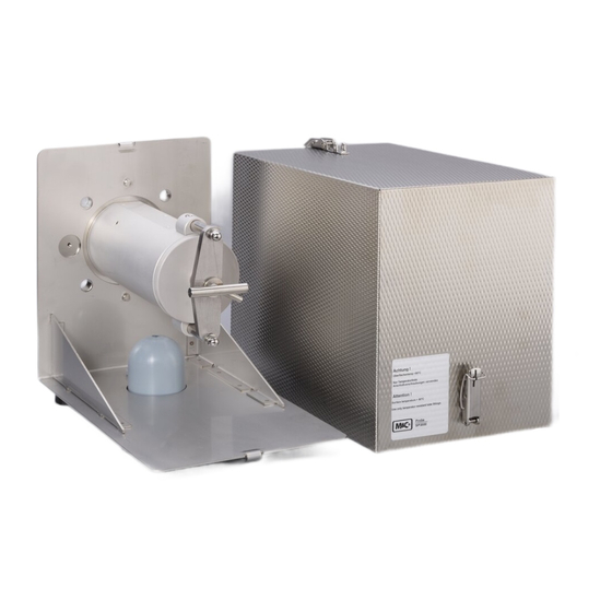
Page 12: Figure 1 Probes Sp3110(V) Without Options With Preliminary Filter Type V20
3-way ball valve 3VA SP3110/3 II 2 G/ 2 < 80 SP3110/V/ II 2 G/ 2 < 80 [176 °F] [185 °F] [176 °F] [185 °F] (Option (Option II 2 G/ 2 < 95 II 2 G/ 2 < 95 [203 °F] [212 °F] [203 °F... -
Page 13: Table 2 Sample Tubes For Use With The Probe Sp3110(V)
For the use of sample tubes in connection with the probe SP3110(V), please look into the following table. Sample Part Max. Material Length Length Connec Tube Connec- “L1” “L tube temp. tion ø tion max” Type °C Tube/ thread OD/ID ø... -
Page 14: Options
OPTIONS The following options 10.1 to 10.9 are available for use in potentially explosive atmospheres. Please seeTable 4 for the markings for the respective zones. Attention must be paid to the operating parameters when selecting options. Warning Diagram with Feeding of calibration gas or back-purging Entnahmesonde Entnahmesonde S ample P robe... -
Page 15: Back-Purging Unit Type Rs
General safety instructions for back-purging and feeding of calibration gas A back-purging gas suitable for the sampling point must be selected for back- purging. The back-purging pressure must always be higher than the process pressure. This minimum pressure must be monitored with a press switch at the inlet side of the accumulator or the check valve. -
Page 16: Option /C/I Feeding Of Test Gas Via Check Valve Behind The Probe Filter With Pneumatic Stop Valve For The Probe Outlet To The Process
For processes with overpressure, this kind of feeding the test gas is not recommended. In this case, you should use an integrated ball valve in the inlet of the probe as stop valve. In principle, you need only a small quantity of test gas for probes with an integrated ball valve, because the probe is separated from the process when the ball valve is activated so that there is no danger of a mixture with the process gas. -
Page 17: Figure 3 Function Schema Of Option 3/2-Way Ball Valve /3Va
For the test gas feeding, the ball valve must be turned to the right side as far as it will go. For the measuring operation, return the ball valve into the neutral position. Ball valve position Measuring Ball valve position Blow back Ball valve position Test gas... -
Page 18: Ball Valve Drive Ms1
10.7 BALL VALVE DRIVE MS1 The following drives are available: Pneumatic drive with spring return type MS/ NC or NO Hereby 2 operating conditions can be realised: a. Using a shut off ball valve VA the conditions: "Open=measuring" and "shut". b. -
Page 19: Technical Data
TECHNICAL DATA Gas sample probe type SP3110V SP3110 (up to 185 °C [365 °F]) (more than 185 °C [365 °F]) Part No. 20S5615 20S5610 Weather protection cover Filter housing material Stainless steel 316/316Ti Sealing materials Graphite, FKM Graphite Probe flange sealing material Graphite Pre-filter/sample tubes Optional, see data sheet 2.14 and 2.17... - Page 20 Gas sample probe type SP3110V SP3110 (up to 185 °C [365 °F]) (more than 185 °C [365 °F]) Control Electronic Power supply 230 V 50/60 Hz or 115 V 50/60 Hz (a) Electrical connection 3 x 1.5 mm Marking II 2 G Ex d ib IIC T3*, others on request Power 400 W Case protection...
- Page 21 Gas sample probe type SP3110V SP3110 (up to 185 °C [365 °F]) (more than 185 °C [365 °F]) Operating temperature -20 up to +185°C [-4 up to 365 °F] Option pneum. drive for ball valve /VA o. /3VA Part No. 20S9055 G 1/4”...
-
Page 22: Maximum Surface Temperature Of The Gas Sample Probe
11.1 MAXIMUM SURFACE TEMPERATURE OF THE GAS SAMPLE PROBE The maximum surface temperature of the gas sample probe depends on the process media temperature and the used options (blow back unit RS, ball valve drive MS1 and probe heating HEX4 or HEX1). The permissible process media temperatures are not allowed to exceed 185 °C [365 °F] at options 2-way-ball- valve VA and 3/2-way-ball-valve 3VA. -
Page 23: Preparations For Installation
PREPARATIONS FOR INSTALLATION • First make sure that conditions at the intended place of use correspond to the data on the rating plate. • The temperature of the process must be taken into account when selecting the sampling point. • Heating of the probe or preliminary filter above the temperature limit given in table 5 must be prevented. -
Page 24: Installation
The prevailing operating parameters must be checked against the following table prior to installation: Operating parameters for combustible gas (SP3110(V)) Gas composition Corrosive Toxic Explosive Zone classification process side Zone classification environment Ignition temperature °C Corresponds gas/vapours (> max. temperature class surface temperature from table 4) Explosion group... -
Page 25: Figure 4 Schematic Drawing Of The Filter Housing Cover
The following procedure is recommended: • Remove the probe cover after opening the two toggle-type fasteners. Schematic drawing of the filter housing cover Figure 4 Turn handle A about one full turn anticlockwise so that the cover is lifted. • Place handle C in position E. -
Page 26: Figure 5 Removal Of The Filter Housing Cover
The following figures illustrate the steps described above. Removal of the filter housing cover Figure 5 • Check that the filter element is screwed on firmly. • Insert the filter holder part again. The filter holder part is closed in reverse order. •... -
Page 27: Connection Of The Sample Line
14.1 CONNECTION OF THE SAMPLE LINE • A ¼” NPT female thread is provided on the probe side for connection of the sample line. Suitable connecting unions for explosion-protected lines in the sizes Ø 6 mm (standard), 8 mm or 10 mm can be screwed into this thread using PTFE sealing tape. - Page 28 When using the option back-purging unit /RS the corresponding line must be connected to the accumulator. A back-purging gas suitable for the sampling point must be selected for back-purging. The back-purging pressure must always be higher than the process pressure. This minimum pressure must be monitored at the inlet side of the accumulator with a pressure monitoring switch.
-
Page 29: Electrical Connections
For option 3VA connect the suitable tube (blow back or test gas) at the probe. A back-purging gas suitable for the sampling point must be selected for back- purging. At sampling points with inerting, back-purging must be performed with corresponding inert gas. It must be ensured that the inert gas does not introduce oxygen or combustible gases into the system. -
Page 30: Start-Up
A fuse suitable for the rated current of the solenoid valve (max. 3xIB per DIN 41571 or IEC 127) or protective motor switch with short-circuit and thermal rapid release (set on the rated current) must be installed in front of the solenoid valve as short circuit protection. -
Page 31: Maintenance
MAINTENANCE When working during operation: High surface temperatures! Touching the surfaces can result in burns. Wear protective gloves. Aggressive condensate possible! Wear safety goggles and suitable protective clothing. The requirements of VDE 0100 and its associated standards and regulations must be observed when erecting and servicing high-voltage power installations Warning with rated voltages of up to 1000 V! Work on the gas sample probe must only be carried out when the environment... -
Page 32: Replacement Of The Filter Element
17.1 REPLACEMENT OF THE FILTER ELEMENT Maintenance of the probe is mainly limited to replacement of the filter elements and inspection of the seals and gaskets. For this: For probes with graphite sealing the lid sealing has to be changed whenever the probe is opened. -
Page 33: Cleaning Of The Probe
17.6 CLEANING OF THE PROBE The gas sample probe must be inspected at suitable intervals in time. Dust layers of more than 5 mm must be removed immediately. The dust deposits under the cover must also be removed. To prevent static charging, the probe should always be cleaned with a moist cloth. -
Page 34: Spare Parts List
20 SPARE PARTS LIST Wear, tear and replacement part requirements depend on specific operating conditions. The recommended quantities are based on experience and they are not binding. Gas sample probe SP3110 and SP3110V (C) Consumable parts (R) Recommended spare parts (S) Spare parts Recommended quantity being in operation [years]... - Page 35 www.mc-techgroup.com SP3110../SP3110V.. | 1.00.02...
- Page 36 SP3110../SP3110V.. | 1.00.02 www.mc-techgroup.com...
Need help?
Do you have a question about the SP Series and is the answer not in the manual?
Questions and answers