Table of Contents
Advertisement
Quick Links
Advertisement
Table of Contents

Related Manuals for M&C PMA20


Summary of Contents for M&C PMA20
- Page 1 Oxygen – Analyzer Series PMA ® PMA20 Instruction Manual Version 1.01.00...
-
Page 2: Dear Customer
With the release of this version all older manual versions will no longer be valid. The German instruction manual is the original instruction manual. In case of ar- bitration only the German wording shall be valid and binding. is a registered trade mark. ® Version: 1.01.00 PMA20 | 1.01.00 www.mc-techgroup.com... -
Page 3: Table Of Contents
Application ................................9 Technical data ............................... 9 Description ................................. 11 Front panel ....................................12 Gas flow diagram of the analyzer PMA20 ........................12 10 The measuring principle ........................... 13 11 Receipt of goods and storage .......................... 14 12 Installation ................................14 12.1... -
Page 4: List Of Illustrations
Figure 1 Dimensions PMA20 ............................... 11 Figure 2 Front panel PMA20 ............................... 12 Figure 3 Gas flow diagram PMA20 ............................12 Figure 4 Scheme of the measuring cell and optical signal processing ..............13 Figure 5 Standard gas conditioning system........................15 Figure 6 Electrical connection PMA20 ........................... -
Page 5: General Information
The requirement of the EU directive 2014/35/EU “Low Voltage Directive“ are met. The compliance with this EU directive has been examined according to DIN EN 61010. Declaration of conformity The EU Declaration of conformity can be downloaded from the M&C homepage or directly requested from M&C. www.mc-techgroup.com PMA20 | 1.01.00... -
Page 6: Safety Instructions
Intended use The PMA20 gas analyzer is intended for use in general purpose areas (non-hazardous environments). It may only be operated in compliance with the information in chapter “8 Technical data”. Only use the device within the permitted temperature and pressure ranges. -
Page 7: Used Terms And Signal Indications
Acute toxicity (oral, dermal, inhalation)! Toxic when in contact with skin, swallowed or inhaled. Corrosive! These substances destroy living tissue and equipment upon contact. Do not breathe vapors; avoid contact with skin and eyes. Hot surface! Contact may cause burn! Do not touch! www.mc-techgroup.com PMA20 | 1.01.00... - Page 8 Protect your eyes while working with chemicals or sharp objects. Wear safety glasses to avoid getting something in your eyes. Wear protective clothes! Working with chemicals, sharp objects or extremely high temperatures requires wearing protective clothes. Wear safety footwear! Use safety helmet and full protective goggles! PMA20 | 1.01.00 www.mc-techgroup.com...
-
Page 9: Introduction
M&C oxygen analyzer PMA20 has a wide variety of applications. The analyzer is a suitable and reliable instrument for monitoring oxygen concentrations in various gas analytical control applications including flue gas-, inert gas-, ambient air-, fermentation processes- and process or laboratory control measurements. - Page 10 Option: PMA20 as solvent-resistant version with special measuring cell type PMC-1LB, material: O-ring: Kalrez®, flow meter: PVDF, tubing and fittings: PVDF/SS 316 02A9005 Option: PMA20/30 as chlorine-resistant version with a special measuring cell type PMC-1CL2, gas paths in PTFE/PVDF hose and with purge gas connections 02A9010...
-
Page 11: Description
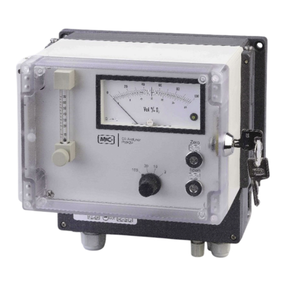
Description The PMA20 is a reliable and easy-to-operate instrument. It is built into a compact wall mounting housing. The transducer unit maintains a constant operating temperature of 50 °C and a flashing LED on the control panel indicates the proper operating temperature of the analyzer. The four measuring ranges are displayed on the analogue meter with 30/ 100% scale. -
Page 12: Front Panel
Needle valve 7-70 Nl/h Measuring range selector switch LED - heating control Figure 2 Front panel PMA20 Gas flow diagram of the analyzer PMA20 1 External fine filter 2 Flow meter with needle valve 3 Measuring cell Figure 3 Gas flow diagram PMA20 PMA20 | 1.01.00... -
Page 13: The Measuring Principle
are compressed. The nitrogen-filled diamagnetic sheres are pushed out of the mag- netic field. This causes a rotation of the dumbbell. The rotation is detected via an optical system consisting of mirror , projection LED and photoelectric cell . www.mc-techgroup.com PMA20 | 1.01.00... -
Page 14: Receipt Of Goods And Storage
Note Installation The PMA20 is intended for stationary operation. In combination with a gas conditioning according to the requirements a long lasting operability and a minimum of maintenance is guaranteed. The sample gas has to be dust free and dry to prevent a contamination and condensation in the analyzer. -
Page 15: Connection Of Sample Gas Inlet And Sample Gas Outlet
Heated gas sample line (e.g. 4M4/6) Sample gas cooler (e.g. ECM-1G) Peristaltic pump or condensate collecting vessel (e.g. SR25.2 or TG-1) Diaphragm pump (e.g. N3) Fine filter (FP-2T) Figure 5 Standard gas conditioning system www.mc-techgroup.com PMA20 | 1.01.00... -
Page 16: Electrical Connection
14.1 Signal output The PMA20 has two signal outputs as standard. One signal is 0-1 V for 100 % O (independent of the chosen measuring range). The second signal is 0-20 or 4-20 mA according to the order with a burden of 300 Ohm for each measuring range. -
Page 17: Starting Up
4. Connect the hose end of the zero-gas bottle connection to the gas inlet of the analyzer. 5. Open the pressure reducer valve slowly, to avoid pressure peaks. 6. Adjust the flow rate to 50 Nl/h at the flow meter. www.mc-techgroup.com PMA20 | 1.01.00... -
Page 18: Cross Sensitivities
-0.26 -0.28 Ammonia -0.17 -0.19 Argon -0.23 -0.25 Benzene -1.24 -1.34 Bromine -1.78 -1.97 Butadiene -0.85 -0.93 n-butane -1.10 -1.22 Isobutylene -0.94 -1.06 Chlorine -0.83 -0.91 Diacetylene -1.09 -1.20 Dinitrogen oxide -0.20 -0.22 Ethane -0.43 -0.47 PMA20 | 1.01.00 www.mc-techgroup.com... -
Page 19: Consideration Of Cross Sensitivities
In the table of cross sensitivities you can read the value for CO at 20 °C of –0.27. This means that for calibration with nitrogen the zero point must be set to +0.27 % in order to compensate the deviation of the display. www.mc-techgroup.com PMA20 | 1.01.00... - Page 20 100 % but on 100 % minus the oxygen concentration (here 95 %). The correction factor is calculated as follows: Correction factor (100 – O -concentration) It is incidental: = 1.0526 (100 – 5) PMA20 | 1.01.00 www.mc-techgroup.com...
-
Page 21: Span Calibration
9. If necessary adjust span accurately according to the check gas concentration with a screw driver at the span potentiometer in the front panel. In case of air e.g. to 20.9 % O 10. Check output signals at 20.9 % O www.mc-techgroup.com PMA20 | 1.01.00... -
Page 22: Measuring
If necessary, lower the dew point by means of a cooler or dryer. For dust filtration use a filter of 2 micron porosity! We will be pleased to inform you about an optimal gas conditioning The analyzer now is ready for operation. PMA20 | 1.01.00 www.mc-techgroup.com... -
Page 23: Closing Down
At the end of the life cycle of our products, it is important to take care of the appropriate disposal of obsolete electrical and non-electrical devices. To help protect our environment, please follow the rules and regulations of your country regarding recycling and waste management. www.mc-techgroup.com PMA20 | 1.01.00... -
Page 24: Spare Parts List
[years] Part No. Indication C/R/S 90A3005 Analog panel meter for PMA20 90A2005 Measuring range switch with wiring and front PCB for PMA20 90A0020 Zero potentiometer 5 kohm 90A0025 Span potentiometer 1 kohm 90A0010 Measuring cell type PMC-1 (not for PMA15) -
Page 25: Figure 7 Overview Risk Assessment
Chemical burns due to aggressive media possible! This applies to all liquids in vessels and in the product. In general, for electrical and mechanical work on the product, wear personal pro- tective equipment (PPE) in accordance with the risk assessment. www.mc-techgroup.com PMA20 | 1.01.00... - Page 26 The product can be transported by 1 to 2 person(s). The instructions for appropri- ate personal protective equipment (PPE) must be observed. The weight specifications are contained in the technical data of this product. Furthermore, the work safety regulations of the operator must be observed. PMA20 | 1.01.00 www.mc-techgroup.com...
-
Page 27: Appendix
Appendix 1. Circuit diagram PMA20 2. Circuit diagram oxygen transducer unit PMA1.02.0 3. Components list circuit diagram PMA1.02.0 (2 figures) 4. Temperature sensor resistance dependent on temperature 5. Installation provisions and spare parts positions Further product documentation can be seen and downloaded from our home page: www.mc-techgroup.com... -
Page 28: Figure 8 Circuit Diagram Pma20
Figure 8 Circuit diagram PMA20 PMA20 | 1.01.00 www.mc-techgroup.com... -
Page 29: Figure 9 Circuit Diagram Oxygen Transducer Unit Pma1.02.0
Figure 9 Circuit diagram oxygen transducer unit PMA1.02.0 www.mc-techgroup.com PMA20 | 1.01.00... -
Page 30: Figure 10 Components List Circuit Diagram Pma1.02.0
Figure 10 Components list circuit diagram PMA1.02.0 PMA20 | 1.01.00 www.mc-techgroup.com... -
Page 31: Figure 11 Components List Circuit Diagram Pma1.02.0
Figure 11 Components list circuit diagram PMA1.02.0 www.mc-techgroup.com PMA20 | 1.01.00... -
Page 32: Figure 12 Temperature Sensor Resistance Dependent On Temperature
Figure 12 Temperature sensor resistance dependent on temperature PMA20 | 1.01.00 www.mc-techgroup.com... -
Page 33: Figure 13 Installation Provisions And Spare Parts Positions
Figure 13 Installation provisions and spare parts positions www.mc-techgroup.com PMA20 | 1.01.00...
Need help?
Do you have a question about the PMA20 and is the answer not in the manual?
Questions and answers